

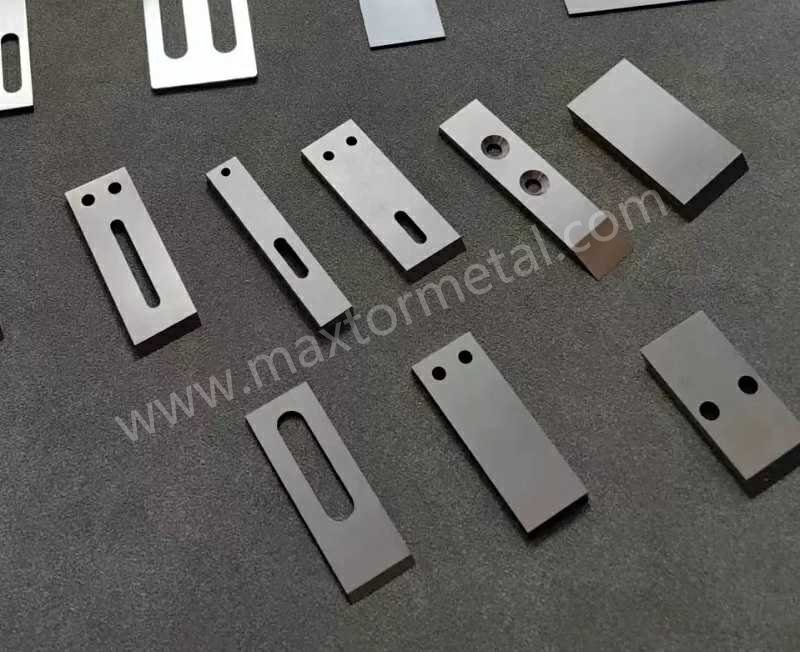
요약 답변: 수중 펠레타이저 라인의 다이 페이스(Die-face)에서 안정적인 전단을 유지하려면 다음 4가지 핵심 변수가 유기적으로 맞물려야 합니다: 초경 그레이드(대부분의 WC-Co 나이프의 경우 HRA 88~92), 날 끝 형상(단순히 '날카로운' 것이 아닌 정밀 제어된 날 끝 R), 접촉 압력 관리(안착 후 미세 조정 방식, 과도한 압력 밀어붙이기 지양), 그리고 순환 수조의 안정성(40~60°C, 필터링 및 탈기 완료). 다이 페이스의 표면 상태나 커터 헤드의 동밸런스를 잡지 않은 채 나이프만 교체하는 것은 초경 나이프로 업그레이드하고도 기대 이하의 성능을 보게 되는 가장 흔한 원인입니다。
다이 페이스 펠레타이징에서 초경(WC) 인서트 나이프란 강철 캐리어 블록에 브레이징(황동 납땜)된 WC-Co계 소결 전단 부품을 말합니다. 이는 연속적인 폴리머 압출 공정 중 1,000 ~ 4,000 RPM으로 회전하는 다이 페이스에 밀착하여 안정적인 전단 날 끝을 유지하도록 설계되었습니다。
초대형 LDPE 및 PP 생산 라인에서 가동 시간이 손실되는 것은 단순히 칼날이 마모되기 때문이 아닙니다. 절단 상태가 불안정해지기 때문입니다. 즉, 미세 분말(fines)이 급증하고, 테일(tails) 현상이 나타나며, 전류값(amps)이 흔들리고, 작업자가 설정을 계속 쫓아가며 조정해야 하는 상황이 발생합니다.
본 가이드는 다이 페이스 커팅 시스템(수중 펠레타이저 및 워터링 펠레타이저)을 위해 작성되었습니다. 인서트 나이프의 그레이드, 날 끝 형상, 접촉 압력, 그리고 순환 수조 제어에서의 아주 미세한 차이가 설비를 몇 주 동안 안정적으로 돌릴 수 있을지, 아니면 오늘 밤 당장 셧다운하게 될지를 결정짓습니다 。
Maxtor Metal의 제품 페이지: 플라스틱 펠렛타이저 블레이드 다이페이스 시스템에 사용되는 모든 범위의 칼날 형태, 치수 및 공차를 다루고 있어 생산, 정비, 구매 부서 간의 용어를 조율하는 데 유용한 참고 자료가 됩니다.
- 대상: 수중(underwater)/수환식(water-ring) 펠레타이저를 사용하는 초대형 LDPE/PP 생산 설비
- 목표: 가동 시간 극대화, 펠렛 품질 안정화, 미세 분말(fines) 및 테일(tails) 감소
- 본 가이드의 주요 내용: HRA 88–92 소재, 설계, 제어, 워터 루프, KPI
WC-Co(초경) 그레이드 및 경도
인서트형 칼날용 초경합금은 일반적으로 코발트 바인더가 포함된 텅스텐 카바이드(WC–Co)입니다. 실제 현장에서 재질(grade) 선택은 경도(내마모성)와 인성(치핑 저항성) 사이에서 균형을 잡는 일이며, 가장 적절한 지점은 수지의 마모성, 필러 함량, 그리고 접촉 제어가 얼마나 안정적인지에 따라 달라집니다.
초경합금의 경도는 일반적으로 로크웰 A 스케일(HRA)로 표기되며, 시험 방법과 스케일 정의는 표준화되어 있습니다. 특히 초경합금의 경우, ASTM B294 — 초경합금의 경도 시험 에서는 로크웰 HRA 시험 절차(다이아몬드 압입자, 10 kgf 예비 하중, 60 kgf 총 시험 하중)를 정의하고 있으며, 더 광범위한 로크웰 시험 방법은 다음 표준을 참조합니다. ASTM E18 — 금속 재료의 로크웰 경도. 또한 많은 시험실에서 로크웰 시험 방식을 다음 표준과 일치시켜 사용합니다. ISO 6508 (로크웰 경도) 표준 간의 일관성을 유지하기 위해.
제조 관리를 위해서는 경도 범위와 함께 미세조직 기준(결정립 크기 및 기공도)을 함께 설정해야 합니다. 두 인서트의 HRA 측정값이 동일하더라도 칼날 끝(edge)에서의 실제 성능은 다르게 나타날 수 있기 때문입니다.
부서 간 용어를 조율 중이라면, Maxtor Metal의 다음 가이드가 펠레타이저 칼날 압력 조절 및 다이 보호 절단 불량을 제어 가능한 설정(압력, 다이 보호, 운전 범위)과 연계하여 설명하므로 유용한 참고 자료가 될 것입니다.
텅스텐 카바이드 인서트 적용 범위
많은 공장에서 다이페이스 절단용 인서트에 적용하는 실무적인 범위는 HRA 88–92. 입니다. 이 범위가 의도적으로 넓게 설정된 이유는 다음과 같습니다.
- 하한값 (≈88–89 HRA): 바인더 함량이 높아 인성이 우수하며, 접촉 제어가 불완전하거나 스타트업 시 마찰이 발생할 때, 또는 다이페이스가 완벽하게 평평하지 않을 때 더 안전합니다.
- 상한값 (≈91–92 HRA): 내마모성이 높으며, 마모성이 강한 컴파운드를 가공하거나 압력 상승 없이 제로 갭(near-zero gap)에 가까운 상태를 유지할 때 유용합니다.
“성적서상의 HRA” 외에 추가로 확인해야 할 사항:
- 소결 카바이드의 결정립 크기 및 기공도 등급 (결정립이 조대하고 기공도가 높으면 간헐적 접촉 시 칼날 끝이 깨지는 치핑 위험이 커집니다).
- 로트(Lot) 간 일관성 (공급업체에 따라 동일한 재질 등급이라도 미세조직이 항상 같지는 않습니다).
사양서를 작성해야 하는 경우, 공인된 초경합금 분류 기준을 참조하고(많은 공급업체가 ISO 적용 그룹을 따릅니다. 다음 참조: ISO 513 초경합금 적용 그룹) 귀사의 파손 모드에 중요한 인수 검사 항목을 확정하십시오.
칼날 끝 반경(Edge radius) 및 표면 조도
수중 절단에서 칼날 끝은 오랫동안 면도날처럼 날카롭게 유지되지 않습니다. 수냉, 열 순환, 간헐적인 마찰 속에서도 안정성을 유지해야 하는 작동면입니다. 일반적으로 다음 두 가지 칼날 파라미터가 예상보다 빠르게 펠렛 품질에 영향을 미칩니다.
- 칼날 끝 반경 (Edge radius) (마이크론 단위가 중요함): 너무 날카로우면 미세 치핑 위험이 커지고, 너무 뭉툭하면 용융 수지를 밀어내어 테일(tails)과 스미어(smear) 현상이 증가합니다. 이러한 트레이드오프 관계는 일반적인 절삭 역학 문헌과도 일치합니다. 즉, 칼날 끝을 라운딩 처리하면 치핑에 대한 내구성은 향상되지만, 반경이 커지면 플라우잉 효과로 인해 추력이 증가할 수 있습니다 (다음 참조: Wyen & Wegener (2010), CIRP Annals — 절삭날 반경이 표면 무결성에 미치는 영향).
- 칼날 끝 표면 조도: 연삭 흔적과 버(burr)는 균열의 시작점이 되며, 다이 랜드에서의 균일한 전단 작용을 방해합니다.
실무적인 접근법은 칼날 끝 반경을 관리 대상 공정 변수로 취급하는 것입니다.
- 단순히 “날카로움”으로 정의하기보다, 목표 칼날 끝 반경 범위를 설정하고 이를 측정(광학 비교기 또는 현미경 사용)하십시오.”
- 재연마 결정은 단순한 육안 검사 대신 펠렛 품질 지표(미세 분말, 테일)와 연계하여 내리십시오.
필러가 함유된 PP/PE용 코팅
필러가 함유된 PP/PE 및 마모성이 강한 마스터배치의 경우, 코팅은 점착을 줄이고 칼날 끝의 마모를 늦추는 데 도움이 될 수 있습니다. 단, 이는 모재의 칼날 끝이 안정적인 경우에만 효과가 있습니다.
운영 측면에서 중요한 사항:
- Coating purpose: anti-adhesion vs abrasion resistance vs corrosion resistance.
- Failure mode: if you see coating flake/chip at the edge early, you likely have an edge-prep or contact-pressure issue before you have a “bad coating” problem.
- Compatibility with regrind: decide whether coated inserts are disposable or re-coatable; build that into the cost model.
In short — materials and grade selection: HRA 88–92 is the starting spec, but grain size, porosity, and lot-to-lot consistency are what decide whether that number translates into stable edge life at the die face.
For lines where the wear mechanism is driven by glass-fiber loading rather than bulk abrasion — and where the blade material is PM stainless rather than cemented carbide — the parallel grade selection logic between M390 and CPM S90V is covered in our guide on powder metallurgy pelletizer blade selection under high glass-fiber wear.
복합 나이프 블록(조합형) 디자인
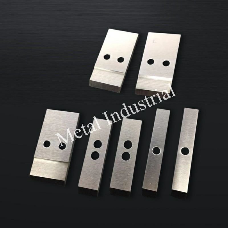
Insert knives rarely fail “because carbide is carbide.” They fail because the composite assembly can’t keep the edge tracking the die face consistently over time.
Brazing and joint integrity
The braze joint is a structural element. If it creeps, cracks, or distorts under thermal cycling, your insert can stay hard and still cut badly.
Maxtor Metal’s QA process for knife block assemblies includes braze gap verification, wetting inspection, and flatness/runout measurement to drawing tolerances — with sample cross-sections as part of the pre-release checklist.
What to check in your own acceptance plan:
- Braze alloy selection suited to operating temperature and corrosion environment.
- Braze gap control and evidence of full wetting (avoid voids at the highest-stress edge zone).
- Post-braze distortion: measure flatness and runout on the assembled block, not just the insert alone.
Carrier stiffness and tracking
Carrier stiffness is what converts a setpoint into a real, repeatable contact condition.
If the carrier flexes, your “pressure” becomes a mix of actual edge load plus vibration — and the vibration is what makes fines and intermittent tails.
Checks that usually pay back:
- 확인하다 hub-to-carrier seating and fastener torque control (repeatability beats “tight enough”).
- 측정하다 다이내믹 런아웃 at operating speed; static runout alone misses a lot.
- Ensure the carrier design maintains stiffness across temperature (thermal growth can change tracking).
Balance and sweep over die holes
A cutter hub can be “balanced” and still cut unevenly if the sweep doesn’t cover the die-hole pattern correctly.
What to validate during commissioning and after major maintenance:
- Sweep coverage: confirm the blade path overlaps the full active die-hole ring, including any segments that are intentionally blocked or blanked.
- Balance at real speed: imbalance raises bearing load, injects vibration, and forces operators to compensate with pressure — which accelerates both knife and die wear.
For the full balance grade calculation, runout acceptance criteria, and QA dossier structure that apply to knife block assemblies at 1,000–4,000 RPM, see our 워터링 펠레타이저용 나이프 블록 적격성 평가 프레임워크.
In short: insert hardness is only as good as the assembly that keeps it tracking the die face — braze integrity, carrier stiffness, and dynamic balance are what the carbide relies on.
현장 불량 급격 해결 트러블슈팅 맵
Use this as a fast “symptom → first checks → adjustment” path before you start changing knife pressure.
- Tails/stringers jump suddenly → verify die-face condition (grooves/high spots), cutter-head runout, 그리고 water temperature stability → then re-check contact pattern and trim pressure.
- Fines climb gradually → verify filtration performance, recirculated debris, and edge finish/wear → then review edge radius targets and regrind thresholds.
- Motor amps drift up at constant throughput → correlate amps with pellet appearance: rising amps + worse pellets usually means rubbing → confirm alignment and reduce contact after stabilization (engage → trim).
- Startup is unstable (freeze-off / tails / vibration) → prioritize thermal balance (water loop temperature/flow distribution, degassing) and clean seating surfaces → only then adjust speed/pressure.
In short: tails, fines, and amps each point to a different root cause — match the symptom to the right check before touching pressure.
나이프 접촉 및 압력 제어
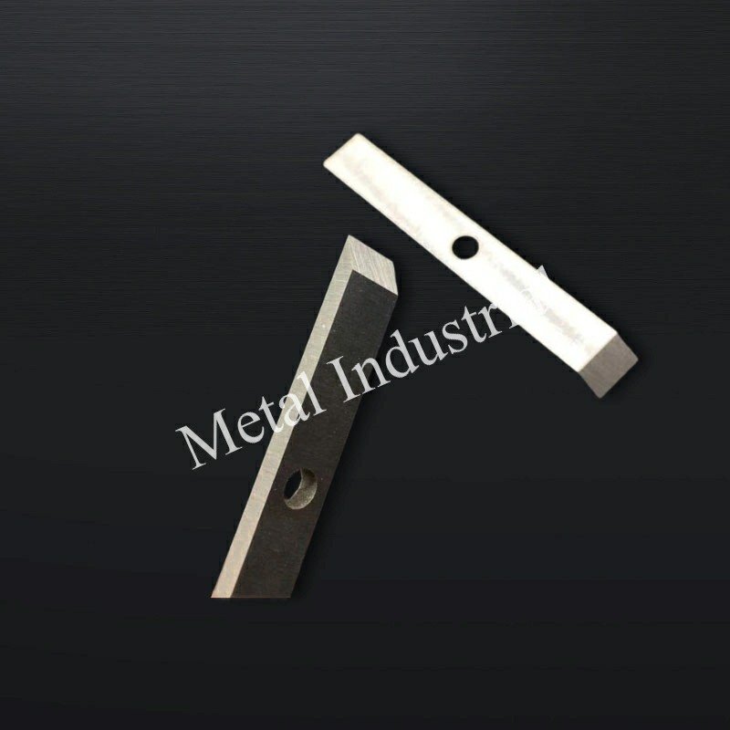
Contact control is where quality and uptime converge. A stable cut usually comes from a narrow operating window: enough force to shear cleanly, not enough to plow the die face.
Pressure and near-zero gap
Many plants aim for a near-zero gap condition (or very small clearance) with controlled contact pressure, because that’s the easiest way to keep pellet length stable.
To keep it stable:
- Engage → trim strategy: engage with higher force to seat and stabilize, then trim down once pellets and amps stabilize.
- Watch motor current trend and pellet appearance together; if current rises while pellet quality degrades, you’re often rubbing rather than cutting.
핵심 요점: If operators routinely “solve” tails by increasing knife pressure, you’ll often buy short-term quality at the cost of rapid die-face grooving.
Alignment and run-in
Alignment problems look like “mysterious” pellet defects because they show up as intermittent tails, twins, or fines spikes.
Run-in should be treated as controlled stabilization, not a trial-by-fire:
- Verify seating surfaces are clean and repeatably torqued.
- Use a short run-in at controlled conditions, then re-check runout and contact pattern.
- If the die face has any feelable groove or high spot, correct it before you chase knife settings. (Die condition drives knife behavior as much as the insert does.)
Speed and cut frequency
Cut frequency is the bridge between polymer flow and pellet geometry. When speed changes, you change:
- Pellet length distribution
- Heat generation at the edge
- The “time under load” per pass
A practical control approach:
- Stabilize throughput, then adjust cut speed to hit pellet spec.
- If you’re increasing speed to “fix” tails, verify the upstream root cause (viscosity, die temperature, water flow) first.
For tacky polymer lines — particularly TPU and EVA — where contact pressure mismanagement is the primary trigger for knife gumming and adhesion buildup, the mechanism-level diagnostic and DLC vs PTFE coating selection logic is covered in our guide on stopping knife gumming in TPU underwater pelletizing.
In short: a stable cut comes from engaging with enough force to seat cleanly, then trimming down — not from chasing defects with increasing pressure.
순환 수조(Water loop) 엔지니어링
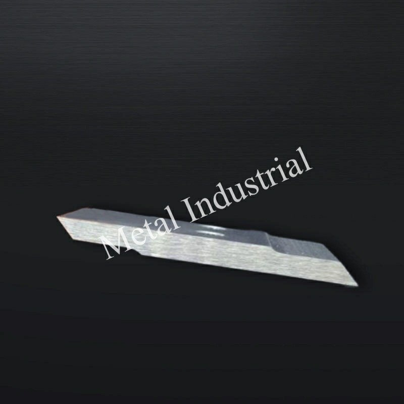
The water loop is not just cooling — it’s a stability system. Water temperature, flow, cleanliness, and entrained gas all show up at the cut.
Temperature and flow
A workable control band for many operations is 40–60°C process water temperature, because it tends to reduce thermal shock while keeping pellets from smearing.
What to manage in practice:
- Temperature stability beats absolute temperature: a drifting loop changes polymer solidification behavior and can look like “random” tails.
- Flow distribution at the die face: dead zones create local freeze-off risk or local over-heating.
If you see startup instability, it’s often a thermal balance problem. Research on die-face pelletizing and freeze-off highlights how heat transfer conditions can drive irregular cutting and tails (see International Journal of Heat and Mass Transfer (2022), article overview). Practical troubleshooting guidance from Plastics Technology also emphasizes that die-hole freeze-off is commonly driven by start-up sequencing, inadequate die heating/insulation, and process fluctuations — see Plastics Technology: Stop die-hole freeze off.
여과 및 탈기
Filtration and degassing are “hidden variables” that decide whether your knife and die face operate in clean water or in a slurry.
- Filtration (coarse protection + side-stream cleanup): Many plants start with a coarse strainer / screen to protect pumps and seals, then rely on side-stream filtration to steadily remove suspended solids without disrupting main flow. For closed-loop water systems, ChemAqua’s guidance describes using progressively finer filters during cleanup (for example, stepping from 50 µm to 20 µm and then to 10 or 5 µm once filters can stay online without blinding) — see ChemAqua: Filtration options for closed-loop systems.
- Degassing: removes entrained air that can cause cavitation, unstable flow, and inconsistent cooling at the die face.
Operational signs you’re under-filtered or under-degassed:
- Gradual fines increase with no obvious geometry change
- Unstable flow indications at constant pump speed
- Rapid edge polish/loss of finish even with stable pressure
Thermal stability and drying
A stable cut is only half the story; you also need stable downstream handling.
- Keep loop control tight enough that pellet surface moisture is predictable.
- If drying performance swings, don’t only blame dryers — verify water temperature stability and degassing first.
In short: water temperature stability, filtration, and degassing are process variables, not maintenance tasks — drifting loop conditions show up as pellet defects before they show up on gauges.
핵심성과지표(KPI) 및 투자회수율(ROI)
A knife program becomes scalable when you translate “feels sharp” into KPIs that predict failure before quality drops.
What changes first when you change inserts or settings?
The table below is a practical “directional map” teams use to predict what will move when you change grade, edge prep, or contact strategy.
Boundary conditions: These are typical trends for die-face cutting on PE/PP lines. Your actual results depend on resin/filler abrasiveness, die-face condition, hub stiffness/runout, and water-loop stability. Validate on your line and document the operating window.
| Change you make | Typical effect on fines | Typical effect on tails/stringers | What to watch operationally | Risk if pushed too far |
|---|---|---|---|---|
| Higher hardness / more wear-resistant insert (within a stable grade family) | Often ↓ over time (slower wear) | Often ↓ if edge stays stable | Track edge micro-chipping and vibration | Can ↑ die-face grooving if contact control is poor |
| Sharper edge / smaller edge radius | Can ↓ initially | Can ↓ initially (cleaner shear) | Monitor sudden fines spikes (micro-chipping) | Higher chipping risk during rub/startup events |
| Larger edge radius / heavier edge prep | Can ↑ if edge starts “pushing” melt | Can ↑ (more smear/tails) | Look for pellet smear and current increase | Over-prep behaves like a worn edge |
| Pressure-heavy strategy (solving defects by loading force) | Mixed; can hide wear briefly | Can ↓ short-term | Watch amps trend and die-face wear | Accelerates die wear; can shorten insert life |
| Engage → trim strategy (seat, stabilize, then reduce) | Often ↓ (less rubbing) | Often ↓ (more stable shear) | Use pellet metrics + current together | Needs repeatable torque/runout control |
Anonymous engineering case (abrasive CaCO₃-filled PP)
To make the “insert vs. process control” discussion concrete, here’s an anonymized field comparison from a continuous underwater pelletizing line processing an abrasive compound.
메모: This example is constructed from typical field patterns observed across pelletizer knife programs; it is not a single customer’s raw inspection record. Operating results will vary based on resin, filler content, die-face condition, and process control maturity.
Material and operating window (held constant): PP homopolymer with 25 wt% CaCO₃ (+0.5–1.0% processing aid), 7.5–8.5 t/h, MFI 8–12 g/10 min; cutter speed 2,700–3,100 rpm; process water 55–65°C; ~850 die holes; 24/7 operation.
Test design: The plant replaced a conventional hardened tool-steel knife with an inserted tungsten carbide cutting edge while holding knife geometry, knife pressure setpoint, cutter speed, die plate, operators, and recipe constant. Replacement was triggered when fines exceeded 1 wt% 또는 tails exceeded 0.5% (not a fixed time interval).
Observed results (16 weeks, 12 campaigns, ~3,250 t processed, 96 pellet samples, 14 blade sets):
- 미분: 1.35 wt% → 0.46 wt% (−66%)
- Tails/stringers: 0.82% → 0.18% (−78%)
- Average blade life: 185 h → 515 h (2.8×)
- Throughput before edge degradation: ~1,480 t → ~4,100 t (2.8×)
- Unplanned shutdowns: 5 events/quarter → 1 event/quarter (−80%)
- Blade change interval: every 8 days → every 22 days (+175%)
First attempt that failed (why “carbide alone” wasn’t enough): The initial trial upgraded blade material only. With no change to die-face condition or cutter-head balance, fines stayed around ~1.1 wt% and several carbide edges chipped after ~120 hours. Inspection found shallow circumferential die-face grooves. After resurfacing the die, dynamically balancing the cutter head, 그리고 reducing knife contact force by ~10–15%, the inserts delivered stable long-term performance.
Operational learning: Teams that trimmed pressure after the first hour (as thermal growth stabilized) saw less die wear and less shift-to-shift variation than teams that increased pressure whenever tails appeared. After operator training to rely on pellet-quality measurements instead of “pressure chasing,” blade-life variation dropped from ~±18% to ~±6% across shifts.
Pellet quality metrics
Track metrics that are fast to measure and strongly tied to customer complaints:
- Fines (% by weight) at a defined sampling method and interval
- Tails/angel hair rate (count-based or weight-based)
- Pellet length distribution (mean and standard deviation)
Tie each metric to the controllable knobs:
- If fines rise while tails stay flat, suspect edge wear/finish.
- If tails rise suddenly, suspect contact pressure, alignment, die face condition, or thermal imbalance.
Knife life and die wear
Treat knife life and die wear as a coupled system:
- A pressure-heavy strategy can extend pellet quality temporarily while accelerating die-face wear.
- A too-hard, too-sharp edge can look great for hours and then chip, creating a sudden fines jump.
Track:
- Knife life hours/tons per insert set
- Die recondition interval and the trigger (groove depth, hole edge rounding)
- Regrind count and thickness loss (if relevant)
Availability, rate, and cost
ROI is usually won by avoiding unplanned stops and stabilizing quality, not by shaving a small amount off unit knife cost.
A simple way to model it:
- Availability gain: reduced stop frequency × average stop duration
- Rate protection: fewer “quality slowdowns” to stay in spec
- Quality yield: reduced off-spec and customer claims
If you already track OEE, add a small set of knife-specific tags so you can separate “knife-driven” events from upstream process events.
In short: the ROI case for tungsten carbide inserts is built on avoided stops and stable quality yield, not on unit-cost comparison — track availability and rate loss, not just blade price.
결론
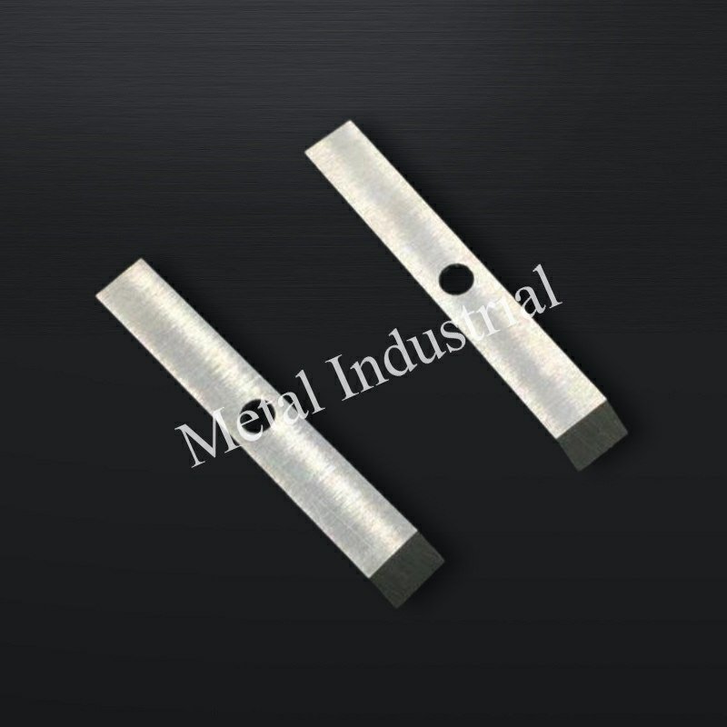
A stable die-face cut is a system outcome: carbide grade and edge prep set the wear/chip behavior; composite design and brazing keep the insert where it should be; pressure/alignment controls keep contact inside a narrow window; and the water loop keeps thermal and contamination variables from drifting.
For Maxtor Metal’s own engineering teams, the practical takeaway is the same as for plant teams: define the insert window (HRA 88–92 is a useful starting point), verify edge radius/finish, validate the braze and carrier stiffness, then lock the water-loop controls before you chase knife pressure.
For medical-grade or food-packaging polymer lines where water-loop chemistry control, ASTM A967 passivation, and contamination traceability are formal quality requirements, the knife specification and loop SOP framework is covered in our guide on 420 vs 440C stainless knife selection and water-loop control for medical polymer pelletizing.
If you’re standardizing blade selection across different die-face systems, Maxtor Metal also maintains a dedicated guide on how to choose water ring pelletizer blades for PE/PP lines that can help align selection criteria across sites.
Maxtor Metal’s plastic pelletizer blade page documents the naming conventions, dimensions, and drawing-controlled tolerances used across knife formats — the reference point for aligning specs between plants and suppliers.
- Key takeaways for materials, design, and operations
- Next steps: selection matrix, SOPs, and SPC logging
FAQs:
Q: 수중 펠레타이저에서 미분(Fines)이 발생하는 원인은 무엇입니까?
A: 미분은 일반적으로 전단 날 끝이 마모되거나 미세 치핑(Micro-chipping)이 생겼을 때, 접촉 압력이 불안정할 때, 또는 순환 수조 내부에서 연삭성 이물질이 재순환할 때 급증합니다. 날 끝 상태와 압력 변화 추이, 필터 여과 성능을 함께 점검하십시오。
Q: 다이 페이스 펠레타이징용 초경 인서트 나이프의 적정 경도는 얼마입니까?
A: 많은 현장에서 WC-Co 나이프의 경도로 88~92 HRA 범위를 목표로 설정한 뒤, 수지의 연삭성(마모성)과 접촉 안정성에 따라 그 안에서 미세 조정을 거칩니다. 경도는 단독 합격 기준으로 취급되어서는 안 되며, 반드시 금상 조직(Microstructure) 제어 플로우와 함께 평가되어야 합니다오。
Q: 워터링 펠레타이저에서 펠렛에 꼬리(Tails) 현상이나 실놀림("엔젤 헤어")이 발생하는 원인은 무엇입니까?
A: 꼬리 현상은 대개 다이 페이스에서의 불안정한 전단 때문에 발생합니다. 축 정렬 불량(Misalignment), 접촉력 부족 또는 압력 흐름 현상, 다이 페이스 마모, 초기 가동 시의 열적 불균형이 주요인입니다. 압력을 무작정 높이기 전에 다이 페이스의 표면 상태와 순환수의 온도 및 유량 안정성을 먼저 검증하십시오오。
Q: 경도가 더 높은 초경 인서트 나이프가 다이 페이스를 손상시킬 수 있습니까?
A: 접촉 제어가 제대로 되지 않거나, 전단 불안정성을 보완하기 위해 작업자가 과도한 압력으로 밀어붙일 경우 손상을 줄 수 있습니다. 가장 안전한 접근법은 '안정적인 정렬(Alignment) + 제어된 압력 미세 조정'을 선행한 뒤, 치핑(날 깨짐) 없이 마모에 견딜 수 있는 최적의 경도 및 날 끝 처리(Edge-prep) 사양을 선택하는 것입니다오。
Q: 수중 펠레타이저 가동 시 순환수 온도는 몇 도로 설정해야 합니까?
A: 一般的な安定領域は40〜60℃ですが、最も重要なのは「温度を一定に保つこと」と「ダイフェイス(金型面)全体に均一な水流を確保すること」です。水温が大きく変動すると、樹脂の凝固挙動(固まり方)が変化し、ペレットの成形不良や欠陥を引き起こす直接的な原因となります。
Q: 수중 펠레타이저 공정수의 일반적인 여과 입도(필터 사이즈)는 얼마입니까?
A: 많은 공장에서 순환 이물질을 줄이고 구성 부품을 보호하기 위해 100~200 µm 범위에서 시작합니다. '정확한' 차단 기준은 수지의 오염도, 마모 입자 적재량, 그리고 전단 품질이 연삭성 물질의 재순환에 얼마나 민감한지에 따라 결정됩니다오。
Q: 제품 품질이 떨어지기 전, 펠레타이저 나이프의 교체 시기를 어떻게 알 수 있습니까?
A: 다음과 같은 선행 지표를 활용하십시오. 미분 발생률 증가, 펠렛 길이 분포의 불균일화, 그리고 일정한 토출량에서의 모터 전류 상승입니다. 많은 작업 팀이 육안으로 불량이 확인될 때까지 기다리지 않고, 설정된 KPI 임계값에 도달하면 나이프를 교체하거나 재연마합니다오。
Nancy Wu, Senior Manufacturing Engineer (PE — Production Engineering), Maxtor Metal. Nancy has 12 years of experience in industrial blade manufacturing and application support, with hands-on expertise in the machining and grinding behavior of common blade materials (D2, M2, H13, powder metallurgy steels, and cemented carbides), coating characteristics, and high-precision CNC grinding programming.
자격증: SME–CMfgE, PMP, Six Sigma Black Belt, ASM International certifications.
How we validate recommendations: The operating windows and troubleshooting guidance in this article are based on production troubleshooting patterns observed across pelletizer knife programs and on manufacturing QA controls. Typical validation steps include measuring edge geometry (edge radius/finish), checking assembled block flatness and runout, verifying braze quality (gap/wetting/alignment), and correlating pellet-quality KPIs (fines/tails/length distribution) with motor current and water-loop stability. Always confirm your site’s limits (die-face condition, hub stiffness/runout, water-loop control) before widening the window or increasing contact force.

 English
  Spanish
  Italian
  French
  Portuguese
  Russian
  German
  Arabic
  Hindi
Hindi  Vietnamese
  Indonesian
  Japanese
  Korean