

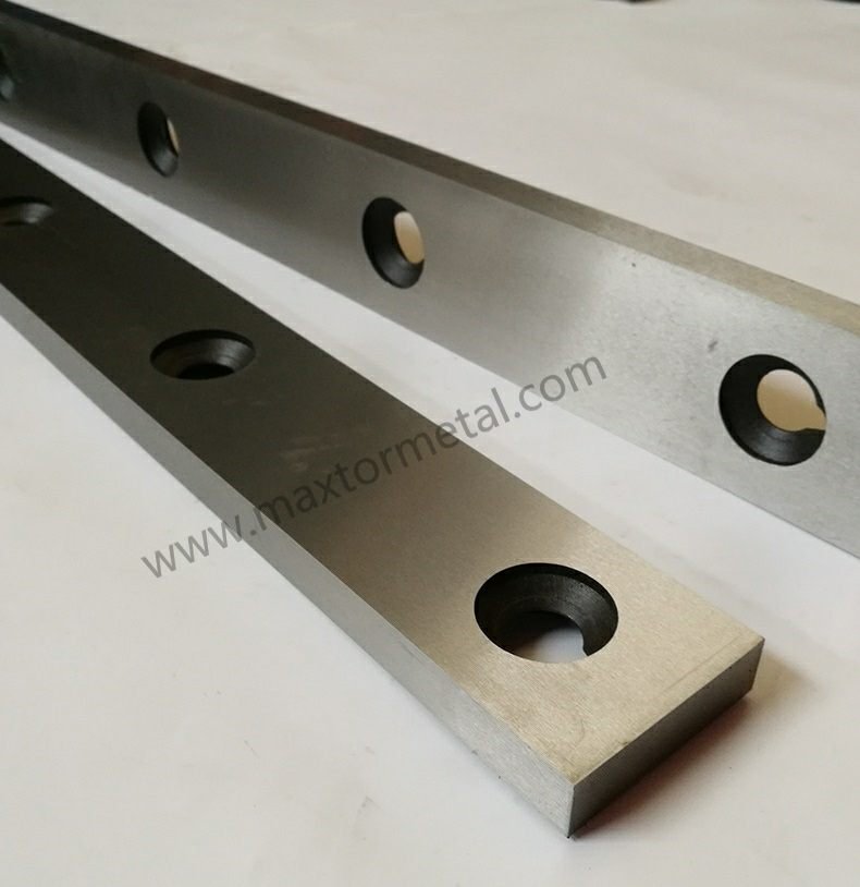
탄소강, 스테인리스강, 고장력강(이종 강종)이 혼재된 라인에서 기요틴 시어(샤링기)를 가동하고 있다면, 당신은 이미 다음과 같은 전형적인 불량 패턴을 알고 있을 것입니다. 버(Burr)가 점점 커지고, 작업자는 날 갭(Gap)을 시시각각 '후행 조정'하느라 급급해지며, 결국 설비 정지 시간은 대응 불가능한 돌발 다운타임으로 이어집니다。
본문에서는 4면 전환식(Reversible) 나이프의 데이터 측정 기반 운영 프로토콜을 정의합니다. 즉, 언제 회전 교체(반전)하고, 언제 재연마해야 하며, 제3자 기관의 품질 감사를 통과하기 위해 무엇을 기록해야 하는지 다룹니다. (영업 목적이 아닌 독자의 이해를 돕기 위한 맥락으로서) 해당 나이프 카테고리는 Maxtor Metal의 샤링기 나이프 제품 페이지에서 확인할 수 있습니다。.
- 목표: 데이터 기반의 4면 리버서블 블레이드 회전 일정 및 재연마 기준 정의.
- KPI: 버(burr) 높이, 간극 정밀도, 칼날 형상, OEE/TCO 영향, 안전.
- 범위: 0.5–20 mm 탄소강, 스테인리스강 및 고장력강; 제3자 감사 대응 가능.
엔지니어링 참고 사항: Maxtor Metal에서 이종 강종 절단 용도로 공급되는 기요틴 시어 나이프는 공장에서 실측한 직선도 및 두께 데이터가 문서로 제공되므로, 나이프 갭의 기준선을 명목상 사양(이론치)이 아닌 실제 나이프 기하학적 형상에 맞춰 정밀하게 정렬할 수 있습니다。 See Maxtor Metal shear blade technical overview]
날 갭(Clearance) 설정의 기본
기준선 및 소재 요인
일관된 기요틴 샤링 블레이드 간극 설정은 기준선과 소재 강도 변화에 따라 이를 조정하는 체계적인 방법에서 시작됩니다.
기요틴 샤링 간극으로 널리 채택되는 기준선은 소재 두께의 ~7%이며, 사용 가능한 범위를 정의하는 두 가지 방향성 실패 모드가 있습니다:
- 과도한 간극 → 찢어짐 및 버(burr) 발생.
- 지나치게 좁은 간극 → 이중 절단/단차 발생.
중요한: 다음과 같이 취급하십시오 ~7% as a 시작 기준점, 보편적인 사양이 아닙니다. 유효한 간극 범위는 장비, 블레이드 상태, 소재의 강도 및 두께에 따라 달라지며, 좌/우/중앙을 측정하고 제어된 테스트 절단을 통해 확인하여 특정 샤링기에서 검증해야 합니다.
가능한 경우, OEM이 명시한 블레이드 간극 지침을 기록하고 따르십시오. 예를 들어, Tennsmith LM/MSE 매뉴얼에는 공장 출하 시 설정된 블레이드 간극이 다음과 같이 명시되어 있습니다. .양 끝단에서 .003 in, 중앙에서 .002 in, 그리고 간극은 반드시 다음과 같아야 함을 강조합니다. 새 칼날 면으로 전환하거나 재연마한 후에 재설정되어야 함 (Tennsmith MSE1016 Operation & Maintenance Manual; 참고 문헌 섹션 참조).
간극 설정 및 검증
간극은 노브 위치가 아니라 측정된 설정값으로 취급하십시오.
최소 공구 키트
- 필러 게이지 (깨끗하고 손상이 없는 것)
- 마이크로미터/캘리퍼스 (소재 두께 + 블레이드 점검용)
- 다이얼 인디케이터 (평행도 점검용)
- 깨끗한 심(shim) (샤링기에 심 팩을 사용하는 경우)
검증 순서 (반복 가능하며 감사에 용이함)
- 장비를 격리/잠금(LOTO)하고 가드/홀드다운이 안전한지 확인합니다.
- 블레이드 시트와 클램핑 면을 청소합니다 (시트 아래의 칩은 “불량 간극”과 같은 영향을 미칩니다).
- 실제 판재 두께를 측정합니다 (공칭 두께를 신뢰하지 마십시오).
- 목표 간극을 설정하고 그 기준(두께 + 소재 등급)을 기록합니다.
- 다음 위치에서 간극을 검증하십시오: 좌/우/중앙 필러 게이지를 사용하여.
- 대표적인 스크랩 소재로 짧은 테스트 절단을 수행하고 절단면을 검사합니다.
핵심 요점: 좌/우/중앙이 일치하지 않으면, 귀하의 “간극”은 서로 다른 세 개의 간극이 됩니다.
단계별 교정 체크리스트(평행도 우선, 그 다음 간극)는 Maxtor Metal의 평행도 및 간극 교정에 관한 기요틴 블레이드 설정 가이드 유용한 참고 자료입니다.
재연마 후 보정
재연마는 장착된 형상과 시트 높이를 변화시킵니다. 귀하의 프로토콜은 “재연마 후 장착”을 제어된 설정 이벤트로 취급해야 합니다:
- 시트를 청소하고, 토크를 확인한 다음, 좌/우/중앙의 간극을 다시 점검하십시오.
- 측정된 값을 새로운 기준선으로 기록하십시오.
- 생산에 투입하기 전에 테스트 절단으로 확인하십시오.
아래 표의 버(burr) 높이 범위는 Maxtor Metal가 샤링 블레이드 고객을 위한 현장 감사 중 블레이드 상태를 평가할 때 사용하는 측정 기준을 반영합니다.
버(Burr) 허용 한계 및 날 기하학적 형상
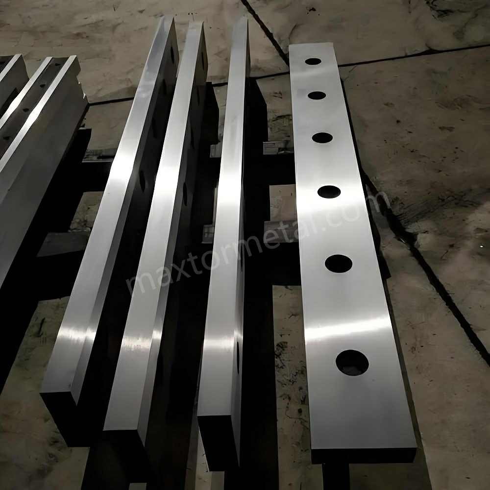
두께 및 강도별 버(burr) 높이 범위
전단 작업 시 버(burr) 높이 임계값은 특정 조치와 연계되어야만 효과가 있습니다. 작업 교대조마다 동일한 칼날 면에 대해 서로 다른 결정을 내리지 않도록 범위를 지정하여 사용하십시오.
내부 합격 기준 예시 (국제 표준 아님)
아래는 생산 관리에서 사용되는 내부 버(burr) 높이 제한의 예시입니다. 아래 표의 측정 기준은 Maxtor Metal가 현장 검토 중 샤링 블레이드 성능을 평가할 때 참조하는 블레이드 상태 임계값을 반영합니다. 검증하고 조정하십시오 OEM 지침, 고객 요구 사항 및 자체 공정 능력에 맞추어.
(A) Low-carbon steel (≤350 MPa)
| Sheet thickness | Green (keep running) | Amber (rotate next planned stop) | Red (rotate now; if persists after verified clearance → regrind) |
|---|---|---|---|
| 0.8–2 mm | ≤0.05 mm | 0.05–0.10 mm | >0.10 mm |
| 2–6 mm | ≤0.08 mm | 0.08–0.15 mm | >0.15 mm |
| 6–12 mm | ≤0.12 mm | 0.12–0.20 mm | >0.20 mm |
(B) High-strength steel (350–700 MPa)
Because of springback and a larger fracture zone, limits are often tightened/shifted.
| Sheet thickness | Green (keep running) | Amber (rotate next planned stop) | Red (rotate now; if persists after verified clearance → regrind) |
|---|---|---|---|
| 1–3 mm | ≤0.07 mm | 0.07–0.12 mm | >0.12 mm |
| 3–8 mm | ≤0.10 mm | 0.10–0.18 mm | >0.18 mm |
| 8–15 mm | ≤0.15 mm | 0.15–0.25 mm | >0.25 mm |
Decision rule
- Green: keep running; log the measurement.
- Amber: rotate at the next planned stop.
- Red: rotate now; if red persists after verified clearance, trigger regrind.
Measurement method (make the data defensible)
- Tooling: a burr gauge or a toolmaker microscope (e.g., 50×), with a defined reading rule.
- Sampling: measure 좌/우/중앙, 3 points each (9 readings total); record max, average, and standard deviation.
- Minimum resolution: use an instrument with resolution at least 0.01mm (preferably finer).
- Repeatability: if multiple shifts measure, run a simple check to confirm different operators obtain comparable readings.
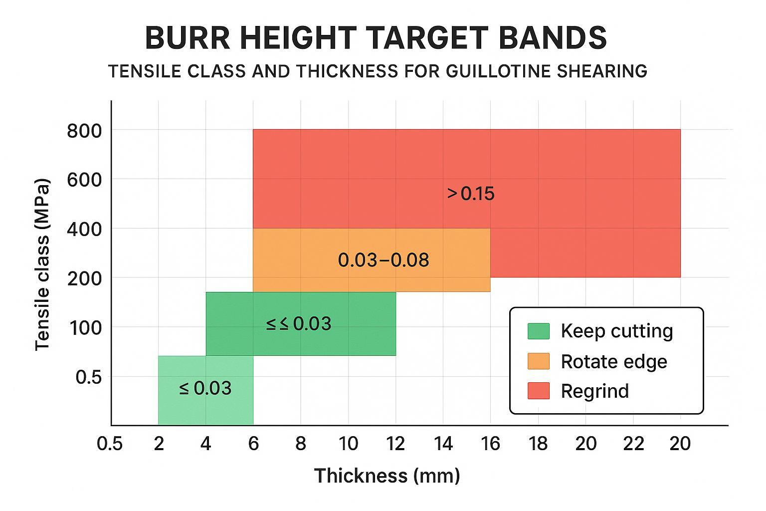
Edge chamfer/hone and visual cues
Burr is not only a clearance problem. A sharp blade with poor gap can burr—but a dull blade with perfect gap can burr too.
Use visual cues that are easy to standardize:
- Reflective bright line along the edge: rounded bevel (edge no longer a crisp line).
- Micro-chipping: repeating burr “spikes” along the cut length.
- Double cut/step: frequently correlates with clearance too tight (verify before regrind).
Sampling and measurement method
If you want burr data you can defend, standardize sampling and the measuring tool.
Sampling cadence (simple default)
- Once per shift per active shear, and once immediately after any clearance change or rotation.
What to record
- Material family + thickness
- Clearance target and measured left/center/right
- Burr height (max observed) + method
- Operator/shift and action taken
Avoid “looks OK.” If you don’t have a dedicated burr gauge, use a consistent comparator method until you do.
나이프 회전 교체 주기 및 이력 로그
Edge-use sequence (four sides)
A 4-edge blade only pays off if your rotation order is standardized.

Recommended rule: rotate in a fixed sequence (Edge 1 → 2 → 3 → 4). If you skip an edge due to a nick, document it and why. A fixed rotation order prevents accidental reuse of a degraded edge and makes the log unambiguous—if you always rotate 1→2→3→4, any out-of-sequence entry is immediately visible as an anomaly.
Rotation “done when…”
- Clearance verified left/center/right
- One controlled test cut inspected
- Log updated (edge number, date, cut count estimate)
Shift-level inspection cadence
A practical cadence for mixed steels:
- Start of shift / job change: quick edge visual check + verify the last recorded clearance basis matches the job.
- During production: burr sample at the defined interval; record any change in cut sound as a note.
- End of shift: decision logged (keep / rotate / pull for regrind).
Rotation record template essentials
Your rotation record is the backbone of traceability—and the easiest place for gaps to hide.
Minimum fields (audit-ready)
- Blade set ID, machine ID
- Edge number in use (1–4)
- Material mix (thickness range + tensile class)
- Clearance target + measured left/center/right
- Burr height + measurement method
- Decision and sign-off
Two fields that make the log useful for cost and planning:
- Estimated cut count or runtime
- Regrind count
That set of fields is enough to be a reversible shear blade rotation log that quality and maintenance can both use.
재연마 기준 및 연삭 관리
Triggers and minimum removal
Regrind is a controlled response to sustained indicators—not the first reaction.
Trigger regrind when BOTH are true
- Burr stays in your red band, and
- Clearance has been verified (left/center/right) and corrected, but burr remains above limit.
Also trigger regrind (or replacement) for chips, cracks, or if the blade has reached OEM minimum dimensions. When chips are the trigger, the fracture mode — fatigue versus impact — determines whether the corrective action is a clearance adjustment or a hardness and grade change. Misidentifying the mode leads to repeat chipping after the next regrind cycle. The Shear Blade Edge Chipping Root Cause Analysis: Fractography and Decision Tree provides the shop-floor reading method and the corresponding SOP corrections.
On minimum removal: remove only what’s needed to restore a continuous edge and the correct bevel. Heavy passes shorten total life.
Preserve geometry and tolerances
Your shear blade regrind criteria should protect geometry first—because geometry drift forces clearance changes, and clearance changes drive burr.
In neutral technical terms (and consistent with how Maxtor Metal approaches precision grinding work):
- Track OEM minimum dimensions and allowable tolerances as controlled limits.
- Control grinding heat; heat tint/discoloration is a reject signal.
- Verify straightness and thickness consistency across the full length.
- Lightly hone/deburr after grinding to avoid installing a fragile burr that breaks off into product.
Post-grind checkpoints to standardize:
- No heat tint on the edge
- Straightness/flatness verified (straight edge or dial indicator method)
- Thickness checked at multiple points (micrometer)
Industry practice for post-grind dimensional tolerances typically targets thickness parallelism within 0.05 mm end-to-end and thickness variation ≤0.025 mm per 300 mm of blade length—confirm against your OEM’s stated limits. Maxtor Metal’s post-grind inspection protocol includes heat-tint verification, full-length straightness measurement, and micrometer-based thickness mapping at five positions before any reground blade is released from production. If regrind intervals remain short despite disciplined geometry control, the underlying blade grade may be the constraint — the carbide microstructure and failure-mode selection framework between D2 and SKD11 is covered in the D2 vs SKD11 tool steel selection guide for shearing blades.
For operations where regrind frequency is the primary cost driver—particularly on AHSS or coated materials—switching to a carbide-inlaid blade construction can significantly extend edge life between regrind events. A full cost-per-meter model and pilot benchmark data are available in the Tungsten Carbide Inlaid Shear Blades ROI Guide for AHSS.
Post-grind installation checks
After reinstalling a reground set:
- Clean seats, torque to spec, verify clearance left/center/right.
- Run a test cut and measure burr.
- Record the baseline so the next shift isn’t guessing.
For the full shim stack calculation method after regrind, see the regrinding thickness reduction compensation and shim stack guide.
마모 보완 신호로서의 모터 부하

Baseline current profile
Motor load/current won’t replace burr or clearance checks, but it can corroborate rising cutting resistance.
Start with a baseline:
- Use VFD/drive readings or installed sensors.
- Baseline by material family and thickness band.
- Trend over weeks, not one day.
그만큼 ReliaMag note on baselining and trending motor current captures the key pitfall: without baselines, trending, and thresholds, current data is just noise.
Alert bands and safe monitoring
Set alert bands relative to your own baseline and validate them on known-good runs.
If you use current transformers, follow CT safety rules: NK Technologies’ guidance on current monitoring for predictive maintenance notes that CT secondaries must not be left open-circuit when energized.
Correlation with burr and clearance
Use current as a cross-check:
- Rising current + rising burr + verified clearance drift → fix setup first.
- Rising current + stable burr → check hold-down, alignment, lubrication, or mechanical drag.
- Stable current + rising burr → likely edge geometry/dullness.
문서화 및 규정 준수(Compliance)
버전 관리, 적용 범위 및 안전 유의사항
Document control
- SOP / Work instruction title: 4-edge reversible blade rotation schedule and regrind criteria
- Document owner: Maintenance / Quality
- Version: v1.0
- Effective date: 2026-07-02
- Review cadence: quarterly (or after any OEM/manual revision)
Revision log (template)
| Version | 날짜 | Changed by | Summary of change |
|---|---|---|---|
| 버전 1.0 | 2026-07-02 | Initial release |
Scope & applicability
This protocol is a best-practice framework for guillotine shears using reversible multi-edge (4-edge) blades on 0.5–20 mm carbon, stainless, and high-strength steels.
Safety & responsibility disclaimer
- This document does not replace your machine OEM manual, lockout/tagout procedures, or site EHS requirements.
- OEM limits and instructions always take precedence (minimum dimensions, allowable straightness/flatness, torque, blade gap/clearance range, and inspection intervals).
- Blade handling and clearance adjustments should be performed only by trained/qualified personnel with appropriate PPE and guarding in place.
- If there is any conflict between this protocol and an OEM manual, follow the OEM manual and record the deviation in the log.
Rotation and regrind traceability
Minimum traceability pack per blade set:
- Blade ID and spec (where available)
- Rotation log (edge usage history)
- Regrind log (date, key checks, pass/fail)
- Nonconformance notes (what happened, what was corrected)
OEM-dependent limits and audits
Write into the SOP that OEM limits win:
- Minimum blade dimensions after regrinds
- Straightness/flatness limits
- Hole/seat wear limits
Attach OEM charts/manual pages as controlled documents (with revision) if your quality system requires it.
Training and continuous improvement
Train for consistency:
- clearance measurement left/center/right
- double-cut vs tearing identification
- burr measurement and recording
- rotate vs regrind decision logic
Then review logs monthly to adjust burr bands to your downstream requirements—not to opinion.
참고 문헌 및 지원 매뉴얼(선택 항목)
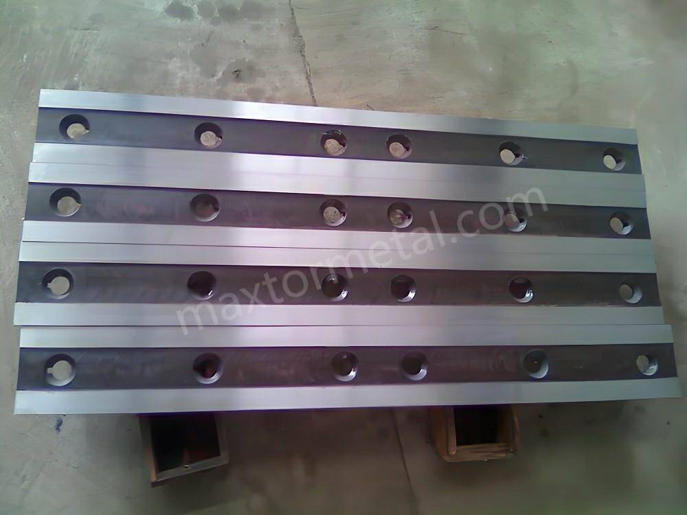
The following publicly available resources support the maintenance philosophy in this article (multi-edge rotation, resetting blade gap after turning/sharpening, and controlling regrind tolerances). Always verify applicability to your specific shear model.
- Tennsmith LM/MSE Series Operation & Maintenance Manual — four-edge blades, factory-set clearance example, and the requirement to reset clearance after turning to a new edge or after re-sharpening: https://www.trick-tools.com/common/documentation/mse1016-manual.pdf
- Genesis GXP Mobile Shear manual excerpt (demolition/mobile shear context; useful for multi-edge rotation mindset and inspection intervals such as 40–80 hours rotation guidance 그리고 rotation when edge radius reaches 1/8 in (3 mm)): https://www.andersonequip.com/web/files/MfrModelDocs/GEM-GXP-broc.pdf
우수 사례 연구(적용 예시)
The following case example is drawn from a maintenance review conducted with a Maxtor Metal D2 shear blade customer. Customer identity anonymized per standard disclosure practice.
Context
- Factory: automotive parts stamping center (anonymous)
- Machine: 3200 mm hydraulic guillotine shear
- Blade: 4-edge reversible D2 shear blades (vacuum heat-treated, 3200 mm, supplied by Maxtor Metal)
- Material: ASTM A36, 4 mm
- Operation: two shifts/year-round
Results represent a single documented maintenance trial; outcomes may vary by machine type, material grade, and operating conditions.
Before (no standardized rotation schedule)
- Rotation triggered inconsistently when burr “looked bad”
- Uneven utilization across edges (Edge 1 over-used; Edge 2 nearly new; Edge 3/4 inconsistent)
- No rotation log
After (measurement-based schedule + rotation log)
Inspection every 120–150 operating hours (interval established from baseline wear data collected during the first two months of the trial; adjust to your actual wear curve and OEM guidance), recording:
- Edge No.
- Operating hours
- Burr height
- 칼날 끝 반경 (Edge radius)
- Operator
Rotate when any of the following occurs:
- Burr > 0.10 mm
- Edge radius ≈ 0.20–0.30 mm
- Cut sound changes noticeably
- Burnished zone increases visibly
Measurement sequence for the first piece each shift:
- Tooling: 50× toolmaker microscope + burr gauge
- Method: left/center/right, 3 points each (9 readings total); record max/avg/std dev; trend for 3 shifts
결과
| 미터법 | 전에 | After (4-month average) |
|---|---|---|
| Max burr | 0.18 mm | 0.09 mm |
| Average burr | 0.11 mm | 0.05 mm |
| Unplanned blade changes | 5 / month | 2 / month |
| Blade removals/installs | 9 / month | 6 / month |
| 스크랩율 | 2.3% | 1.1% |
| 설비종합효율(OEE) | 82.4% | 85.6% |
메모: The burr-height thresholds and rotation intervals shown above represent an example of an internal production standard for a 4 mm low-carbon steel application. Actual acceptance limits should be validated against the machine OEM recommendations, customer quality requirements, material grade, and sheet thickness.
결론
A 4-edge reversible blade gives you four chances to stay ahead of burr and downtime—if you manage it like a controlled process.
Tie actions to quantified thresholds: verify clearance, measure burr, rotate to the next edge first, and regrind only when limits persist across a verified setup. Done well, this stabilizes cut quality, extends rotation and regrind intervals, lowers TCO, and protects OEE.
That’s why Maxtor Metal includes rotation log templates and regrind criteria checklists in its blade maintenance documentation—the measurement discipline is built into the delivery, not left to be reconstructed at the machine.
If you want a reference point for the blade type discussed here, see the Maxtor Metal precision shear blades for guillotine applications for tooling specifications and contact options.
FAQs:
Q: 기요틴 시어(샤링기)의 나이프 갭(클리어런스) 설정 시 적절한 초기 기준값은 얼마입니까?
A common baseline is around 7% of material thickness, then adjust for material strength and actual edge results. The Shear Fundamentals training note explains both the baseline and the failure modes.
Q: 전단 버(Burr)의 원인이 날 갭(클리어런스) 불량인지, 아니면 칼날 마모(무뎌짐) 때문인지 어떻게 구별합니까?
A: 먼저 칼날의 좌측, 중앙, 우측 3개 지점의 갭을 실측 검증하십시오. 정밀 조정 후에도 버가 계속 발생한다면 날 끝의 기하학적 형상 변화(베벨 라운딩 현상, 미세 치핑)를 의심해야 합니다. 절단면에 '이중 전단면(ดับเบิ้ล 컷) 또는 단차'가 보이면 갭이 너무 타이트한 상태이고, '뜯겨짐(인장 파단) 및 중증 버'가 발생하면 대개 갭이 너무 넓은 상태를 의미합니다。
Q: 4면 전환식(Reversible) 샤링기 나이프는 언제 회전 교체(반전)해야 합니까?
A: 전단 버(Burr) 치수가 관리 기준의 '황색 경고 구간(Amber band)'에 진입하거나, 초기 날 끝 라운딩 현상이 보일 때 즉시 반전하십시오. 이를 통해 계획 정지 시간 내에 작업을 완료할 수 있습니다. 나이프 회전 교체는 정밀 재연마보다 비용이 훨씬 저렴하며 설비종합효율(OEE)을 방어하는 핵심 수단입니다。
Q: 나이프를 회전 교체(반전)하는 대신 재연마를 진행해야 하는 타이밍은 언제입니까?
A: (1) 새로운 날로 회전 교체하고 (2) 날 갭(클리어런스) 및 평행도를 실측 검증한 후에도 전단 버(Burr)가 관리 한계치를 초과할 때 재연마를 실시하십시오. 또한, 날 끝에 치핑(이가 빠짐), 크랙(균열)이 발생했거나 OEM 규격의 최소 한계 치수에 도달한 경우에도 재연마 또는 교체가 필요합니다。
Q: 품질 감사를 통과하기 위해 나이프 회전 교체 기록부(Rotation log)에 반드시 포함해야 할 항목은 무엇입니까?
A: 나이프 ID, 설비 ID, 사용 날 번호, 피삭재 강종/두께, 목표 갭 치수 + 실측 갭 치수(좌/우/중앙), 전단 버(Burr) 높이 + 측정 방식, 조치 사항, 최종 승인 서명이 포함되어야 합니다. 여기에 총소유비용(TCO) 분석을 위해 누적 컷 수/가동 시간 및 재연마 횟수를 추가하십시오。
Q: 모터 전류 모니터リング(부하 감시)으로 전단 버(Burr) 및 나이프 갭(클리어런스) 실측 검사를 대체할 수 있습니까?
A: 불가능합니다. 전류값은 교차 검증용 신호이자 트렌드 지표일 뿐입니다. 절단 저항의 상승을 조기에 감지할 수는 있지만, 물리적인 실측 없이는 그것이 갭 변동(흐름 현상) 때문인지 아니면 날 끝 형상 변화 때문인지 정확히 진단할 수 없습니다 。
작가
제시 쉬 — Senior Quality Engineer, QA (Quality Assurance), Maxtor Metal
- Experience: 15 years in industrial blade quality assurance and failure analysis
- Focus: diagnosing edge chipping and abnormal wear; distinguishing heat-treatment issues vs. material segregation
- Certifications: ASQ-CQE, ISO 9001 Lead Auditor, ASNT Level II

 English
  Spanish
  Italian
  French
  Portuguese
  Russian
  German
  Arabic
  Hindi
Hindi  Vietnamese
  Indonesian
  Japanese
  Korean