

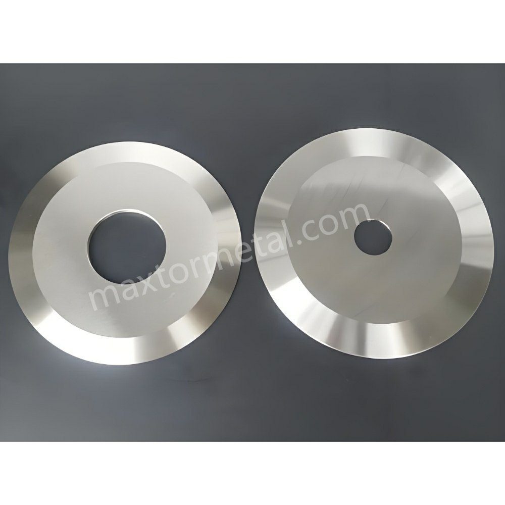
뱀형 절단/스네이크 컷(슬릿 라인 이탈 또는 편심 드레이프라고도 함)은 절단된 에지가 직선적이고 재현 가능한 경로를 유지하지 못할 때 발생합니다. 스트립 레인이 "늘어지거나" 진동하거나 미세하게 이동하여 권취된 롤의 레이어가 더 이상 중앙에 정렬되지 않는 현상입니다. 이를 단일 파라미터의 결함이 아닌, 슬리팅 및 권취 시스템 전체의 안정성 문제로 접근하여 해결해야 합니다.
이 체크리스트는 대부분의 유지보수 및 공정 팀이 현장에서 문제를 해결하는 방식을 반영합니다. Maxtor Metal의 필드 엔지니어링 팀이 셋업(설정) 시에는 양호해 보이던 절단면이 고속 운전 시 불안정해지는 원인을 추적하고 해결할 때 사용하는 진단 시퀀스를 기반으로 작성되었습니다.
핵심 요점: 스네이크 컷(snake cut)이 속도, 롤 빌드(roll build) 또는 레인 위치에 따라 변하는 경우, 먼저 원인을 분리하는 것부터 시작하십시오. 측면 힘(lateral force)이 어디에서 발생하는지 (나이프 힘 vs. 웹 역학 vs. 공기/정전기) “노브를 돌리기(설정을 조정하기)” 전에.”
이 시스템 우선 진단 접근 방식은 단일 변수 수정으로 해결되지 않는 필름 및 부직포 슬리팅 라인의 레인 이탈(Lane Drift) 문제를 겪는 고객을 지원할 때 Maxtor Metal의 애플리케이션 엔지니어링 팀이 적용하는 진단 프레임워크입니다。
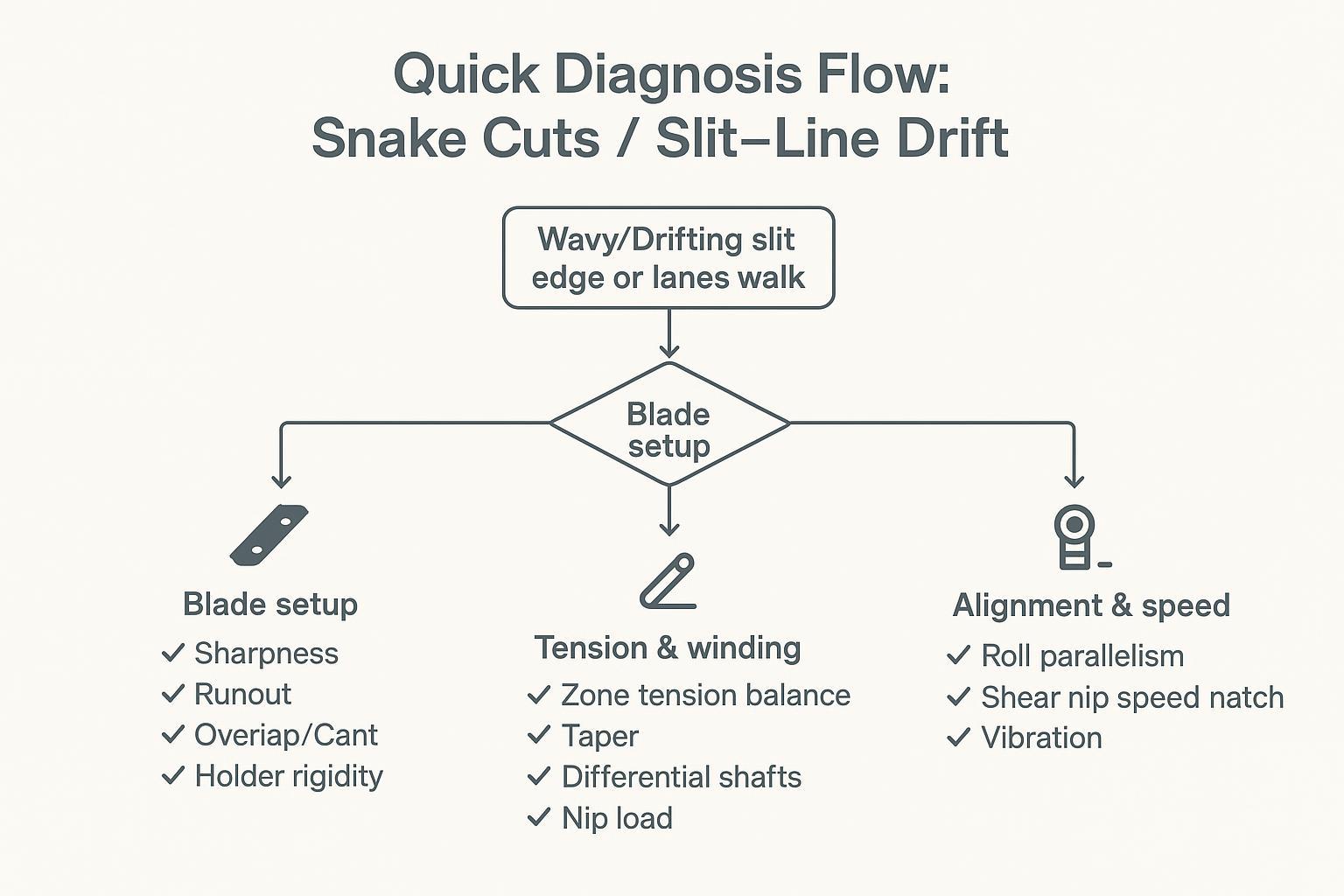
빠른 진단 플로우
블레이드 문제를 의심해야 할 때
- 문제가 특정 레인에 국한됨 (인접한 레인은 위치를 유지하는 동안 한두 개의 레인이 드리프트됨).
- 드리프트가 시작됨 슬리팅 포인트 바로 그 자리에서, 저속에서도.
- 최근에 나이프, 스페이서, 홀더를 교체했거나 나이프 스택을 이동했습니다.
- 드리프트가 “회전당 1회” 반복되는 특성을 보입니다 (종종 런아웃이나 시트의 정렬 불량과 관련됨).
빠른 점검 사항:
- 나이프 스택의 청결 상태를 확인하십시오 (단면에 필름, 접착제, 버(burr)가 끼어 있지 않은지).
- 드리프트가 발생하는 레인의 아버/나이프 단면에서 다이얼 인디케이터로 런아웃을 점검하십시오.
- 오버랩/인게이지먼트(overlap/engagement) 및 캔트/트램(cant/tram)이 절단 방식에 맞는 예상 범위 내에 있는지 확인하십시오.
장력/권취 문제를 의심해야 할 때
- 드리프트가 악화됨 롤 직경이 커질수록.
- 결함이 다음 요인에 따라 레인 간에 “이동”함 코어 위치 또는 터렛 변경.
- 다음 현상이 관찰됨 텔레스코핑(telescoping), 느슨한 가장자리 또는 레인 간 경도 편차.
- 다음 조치를 취할 때 드리프트가 즉시 개선됨 속도를 줄이거나 또는 장력 설정값을 변경할 때.
빠른 점검 사항:
- 언와인드/미드웹/리와인드 구간의 장력을 비교하십시오 (실제값 vs 설정값).
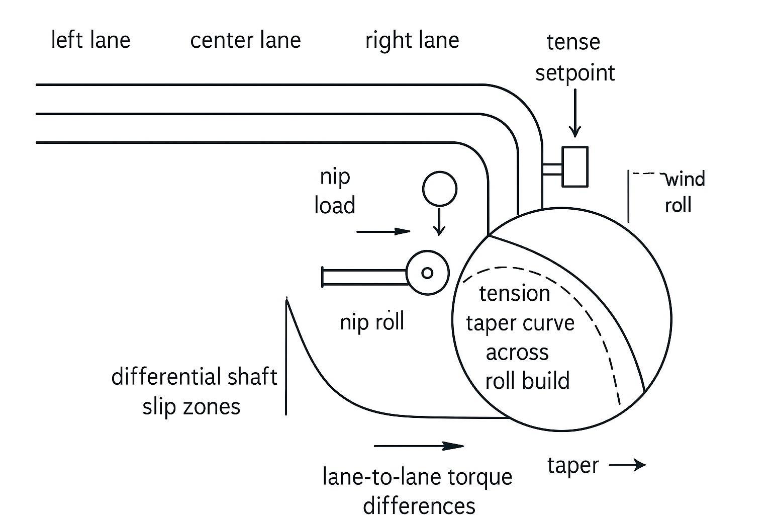
- 롤 빌드 전반에 걸친 테이퍼 장력(taper tension) 동작을 확인하십시오.
- 디퍼런셜 샤프트 슬립(differential shaft slip)이 레인별로 제대로 작동하는지 확인하십시오 (고착된 요소가 없는지).
정렬/속도 문제를 의심해야 할 때
- 유지보수, 베어링 교체 또는 충격/과부하 이벤트 후에 드리프트가 악화됩니다.
- 웹이 상류에서는 잘 추적되다가 특정 롤이나 닙(nip)을 지난 후 편향됩니다.
- 진동이 들리거나 느껴지고, 패턴 마크가 보이거나, 에지 가이드가 흔들립니다.
빠른 점검 사항:
- 롤 평행도 및 닙 밸런스; 명백한 왜곡(skew)이나 불균일한 마모가 있는지 확인하십시오.
- 전단 닙에서의 속도 매칭 (나이프 속도 vs 웹 속도).
- 베어링 상태 및 진동 (온도, 소음, 가능한 경우 스펙트럼 분석).
스네이크 컷 원인 분석 매트릭스
설정을 조정하기 전에 이 표를 신속한 분류 참고 자료로 사용하십시오.
| 증상 패턴 | 가장 가능성 높은 하위 시스템 | 최우선 점검 사항 |
|---|---|---|
| 특정 레인 드리프트, 나이프에서 시작됨, 저속에서도 발생 | 블레이드 / 홀더 | 영향을 받는 레인의 아버 + 나이프 단면의 TIR; 안정적인 레인과 비교 |
| 롤이 빌드될수록 드리프트가 악화됨; 속도가 떨어지면 개선됨 | 장력 / 디퍼런셜 권취 | 각 구간의 실제 장력 vs 설정 장력; 디퍼런셜 샤프트 슬립 토크 |
| 유지보수 또는 기계적 이벤트 후 발생한 드리프트 | 정렬 / 베어링 | 롤 평행도, 베어링 온도 및 진동 스펙트럼 |
| 마더 롤(Parent roll) 로트 또는 레인 위치(가장자리 vs 센터)에 따라 달라지는 드리프트 | 소재 / 두께(게이지) 프로파일 | 폭 방향(Cross-web) 두께 편차, 마더 롤 위치와 레인 간 경도 상관관계 |
| 속도가 빨라질수록 드리프트가 악화되고, 레이온 압력(lay-on pressure)이 증가하면 개선됨 | 공기 유입(Air entrainment) / 정전기 | 감속 테스트, 이오나이저 출력 및 접지 연속성 점검 |
나이프 세팅 및 공차
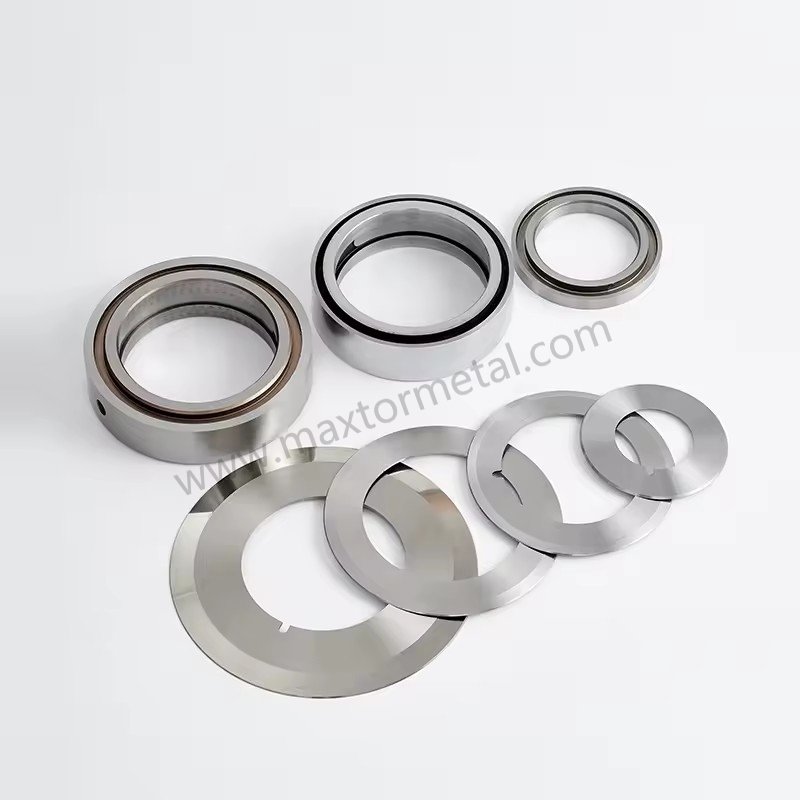
예리함(Sharpness), 런아웃(Runout), 오버랩(Overlap), 캔트각(Cant)
스네이크 컷(Snake cuts)은 종종 작고 반복적인 측면 편향에서 시작됩니다. 많은 라인에서 “칼날로 인한” 사행(wander) 여부를 증명하는 가장 빠른 방법은 중요한 위치의 런아웃을 측정하는 것입니다.
- 날카로움: 무뎌진 칼날 끝은 절단력을 증가시키고, 특히 고속에서의 박막 슬리팅 시 웹을 “조향(steer)”하여 경로를 이탈하게 만들 수 있습니다.
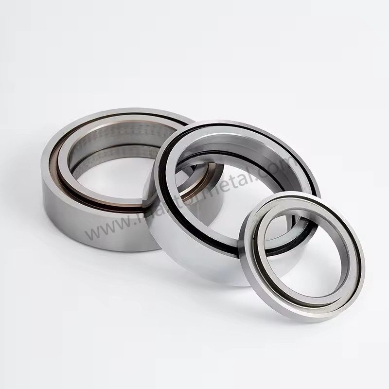
- 런아웃 (TIR): 측정하기 편한 한 지점만 확인하지 말고, 아버 숄더(arbor shoulders), 스페이서 단면, 칼날 단면을 모두 점검하십시오. 총 흔들림(Total Indicated Runout, TIR)을 다음 범위 내로 유지하십시오. ≤0.025–0.050 mm (0.001–0.002 in) 어셈블리 전체에 걸쳐 유지해야 합니다. Maxtor Metal의 수입 검사는 배치별로 칼날 단면과 아버 접촉면 모두에서 TIR을 기록하므로, 칼날 교체 후 드리프트 문제가 발생했을 때 현장 측정값을 문서화된 공장 데이터와 비교할 수 있습니다. 축 방향 및 반경 방향 TIR에 대한 측정 우선 처리 방법(저온에서 고온으로의 드리프트 검증 프로토콜 및 각 런아웃 모드가 유발하는 결함 메커니즘 포함)은 다음을 참조하십시오. 축 방향 런아웃, 동적 TIR 및 슬릿 에지 품질.
- 오버랩 / 맞물림(Engagement): 사용하는 방식과 소재에 맞게 오버랩을 안정적인 최소값으로 설정하십시오 (일반적으로 다음 값에서 시작) 5–1.2 mm / 0.020–0.045 in (표준 전단 필름 슬리팅 기준). 과도한 오버랩은 열과 측면 하중을 가중시키면서 기계적 문제를 일시적으로 가릴 수 있습니다. 박막(PE/PP/PET <50 μm)의 경우, Maxtor Metal의 필드 엔지니어링 팀은 0.50–0.75 mm를 시작 범위로 사용하고 에지 품질 및 절단력 추이에 따라 조정합니다. 셋업 중 오버랩, 캔트각, 스프링 프리로드(preload)가 어떻게 상호 작용하는지에 대한 자세한 내용은 다음을 참조하십시오. 제로 클리어런스 전단 슬리팅을 위한 스프링 로디드 셋업: 오버랩, 캔트각 및 프리로드 제어.
- 캔트(Cant) / 트램(Tram): 캔트각을 제조업체 사양 내로 유지하십시오 (일반적으로 0.25°–0.5°). 장비의 트램(tram)이 올바르게 정렬되지 않으면 셋업 시에는 절단면이 괜찮아 보이지만, 속도가 빨라지고 힘이 증가함에 따라 불안정해질 수 있습니다.
전단 절단(Shear cutting) 참고 자료로, DIENES Slitting Reference Guide는 오버랩을 “다다익선” 식의 설정이 아닌 제어 변수로 다루는 방법에 대한 유용한 기준을 제공합니다 (다음 참조 DIENES 슬리팅 참조 가이드, 제2판 (PDF)).
코팅 선택도 검토 중인 라인(특히 DLC 또는 PTFE 코팅이 드리프트 거동 및 세척 주기에 영향을 미치는지 여부)의 경우 다음을 참조하십시오. 슬리터 원형날용 DLC vs PTFE 코팅: 마모 한계(Wear-limited) vs 점착 이송(Transfer-limited) 선정 가이드.
홀더 강성 및 측면 하중
우수한 칼날을 사용하더라도 홀더가 유연하거나 측면 하중 변동을 허용하는 스택 구조라면 고속 작동 시 드리프트가 발생하게 됩니다.
일반적으로 효과적인 점검 사항:
- 홀더가 평평하게 안착되었는지, 스택 전체에 걸쳐 일관되게 클램핑되었는지 확인합니다.
- 하중 하에서 미세한 움직임이 있음을 나타내는 프레팅(fretting), 고착(galling) 또는 마모 흔적이 있는지 검사합니다.
- 스페이서가 측면 편향으로 이어지는 “공차 누적(tolerance stacking)”을 일으키지 않는지 확인합니다 (특히 다중 레인 구성 시).
- 롤 권취(roll build) 또는 온도 상승과 상관관계가 있는 측면 하중 증가를 모니터링합니다.
스페이서 적층(stack-up) 문제는 종종 내경 끼워맞춤 정밀도(bore fit precision)에서 비롯됩니다. 내경-아버 간 위치 결정 정확도를 확립하는 ISO 286 끼워맞춤 선택 로직과 칼날 스택이 생산에 투입되기 전 조립된 TIR을 검증하는 방법은 다음을 참조하십시오. 중앙 내경 공차 및 런아웃: 고속 슬리터 나이프의 ISO 286 적합성 최적화.
공급 품질은 대부분의 팀이 생각하는 것보다 셋업 안정성에 더 큰 영향을 미칩니다. 경도가 불일치하거나 치수 편차가 있는 칼날 로트는 셋업 문제처럼 보이지만 셋업 조정으로는 해결되지 않는 변수를 유발합니다.
Maxtor Metal는 모든 원형 슬리팅 칼날 출하품에 대해 경도, 치수 검사 및 열처리/로트 추적성 기록을 문서화합니다. 따라서 칼날 교체 후 드리프트 문제가 발생할 때 증상으로부터 역추적하는 대신, 입고된 배치에 대해 검증된 데이터로부터 조사를 시작할 수 있습니다.
칼날이 기존 홀더, 아버 또는 엔지니어링 도면과 일치해야 하는 OEM/ODM 프로젝트의 경우, Maxtor Metal는 단순한 칼날 교체 작업이 기하학적 시행착오의 반복으로 변하지 않도록 완전한 맞춤형 사양 지원을 제공합니다.
다중 레인 설정에서 칼날별 두께 편차가 슬릿 폭 오차로 누적되는 방식을 지배하는 적층 계산법과 교체 시 축 방향 이동을 최소화하기 위한 스페이서 매칭 원칙은 다음을 참조하십시오. 다중 칼날 슬리팅에서 누적 두께 공차 제어.
전단(Shear) vs 면도날(Razor) vs 크러시(Crush) 절단 방식의 선택
가공 소재 및 해결하고자 하는 결함에 맞게 절단 방식을 매칭하십시오:
절단 방식을 선택하기 전에 베벨 형상(bevel geometry)도 기재의 강성(rigidity)과 일치해야 합니다. 얇은 PE 필름에 효과적인 싱글 베벨은 PET 라미네이트에서는 다르게 작동합니다. 싱글, 더블 및 컴파운드 베벨 프로파일을 아우르는 강성 기준 선택 프레임워크는 다음을 참조하십시오. 원형 슬리터 칼날을 위한 싱글, 더블 및 컴파운드 베벨.
- 전단 슬리팅 (Shear slitting): 일관된 에지 품질이 필요하고 기하학적 요소(런아웃, 오버랩, 측면 하중)를 유지할 수 있을 때 가장 적합합니다. 기계적 기준이 올바를 때 안정적인 경향이 있습니다.
- 면도날 슬리팅 (Razor slitting): 박막 슬리팅 시 간결하고 깔끔하지만, 블레이드 상태, 홈 위치 및 웹 안정성에 민감합니다. 홈 위치가 매우 중요합니다. 웹 두께에 비해 홈이 너무 얕으면 웹 장력 하에서 블레이드가 측면으로 휘어져 웹 속도 변화에 따라 절단 경로가 어긋나게 됩니다. 반대로 너무 깊으면 웹이 홈 가장자리를 감싸게 되어 미세한 측면 장력 불균형에도 트래킹이 민감해집니다. 또한 고속 주행 시 웹이 에어 필름 위에 뜨거나, 정전기로 인해 가이드 표면에 대한 측면 흡착력이 증가할 때 드리프트 현상이 빠르게 나타날 수 있습니다.
- Crush slitting: Can be forgiving in some setups but can also amplify wandering when rubber/anvil conditions vary or when heat builds.
| Substrate / Film Category | 권장 방법 | 주요 장점 | Drift Risk Factor |
|---|---|---|---|
| Thin Polyolefin (BOPP / PE) | Razor in groove / Shear | Clean slit edge, minimal dust | Blade deflection, air floating |
| Rigid / High Modulus (PET, PVC) | 전단 슬리팅 (Shear slitting) | Precise cut geometry, clean edges | Knife runout, cant misalignment |
| Thick / Laminated Films | Shear / Heavy Crush | High shear force capacity | Side-load variation, blade wear |
For a DOE-based framework mapping how overlap depth and side clearance interact across these substrate categories—including a Pareto trade-off model between edge quality and knife life—see Optimizing Circular Knife Overlap Depth and Side Clearance.
If you’re seeing snake cuts only on certain SKUs, reassess whether the method matches film thickness, modulus, COF, and speed window.
장력 및 권취 제어
Setpoints and profiles
Tension isn’t just a number—it’s a profile across zones and over time. A stable slit path depends on a stable web strain state.
Practical rules that hold up:
- Keep tension stable across unwind → process span → rewind, and verify actual load cell measurements against controller setpoints. Tension shifts exceeding ±5%–8% from target are often enough to induce lateral web slip and initiate slit-line drift. Maxtor Metal’s field team uses this ±5%–8% band as the flag threshold when reviewingtension logs during post-drift investigations on customer lines.
- Use taper tension intentionally; as diameter increases, tension often needs to decrease to avoid telescoping, edge buckle, or crushed cores.
For a standards-based starting point on web tension guidance, TAPPI publishes tension guidance documents such as TAPPI TIP 0200-01:2021 (web tension guidelines).
Differential shafts and nip
Differential winding is often the difference between “lanes that behave” and “lanes that walk.” When lanes build diameter at slightly different rates, the system needs a controlled way to equalize torque so one lane doesn’t go slack and start wandering.
Checks:
- Confirm differential elements actually slip under the expected torque range.
- Validate nip load is balanced across the roll face; uneven nip can create lane-to-lane traction differences.
- Review taper tension alongside differential settings; if you tighten tension as diameter grows, you can overload one lane and destabilize tracking.
Transitions and traction
A lot of snake cuts are “transition defects”:
- acceleration to production speed
- splice passage
- turret transfer
- roll hardness change as diameter builds
During transitions:
- Confirm web path traction is consistent (no sudden slip at a particular roll).
- Reduce speed briefly as a diagnostic. If drift drops immediately, suspect air/traction/static dynamics before you change knives.
- Treat edge guide hunting as a symptom—often caused by tension oscillation, misalignment, or unstable traction.
정렬 및 속도 동기화
Rolls, shafts, and nip balance
If the web is being forced sideways by geometry, no knife setting will “hold it straight” consistently.
- Check roll parallelism relative to the machine centerline.
- Inspect roll faces for taper, wear, contamination, or damage.
- Verify nip pressure distribution; uneven nip can steer the web.
A practical reference on the fundamentals of centerline tracking and lateral motion causes is Walker’s compilation in the web handling community (see Web Lines: Walker on Web Handling (2003–2014 compilation PDF)).
Speed differential at shear nip
For shear slitting, speed mismatch can create a lateral force component at the cut.
Checklist:
- Verify knife surface speed matches the web where required by your slitting method.
- Confirm drive coupling/backlash isn’t creating periodic speed variation.
- If drift scales with speed but not tension, suspect speed match and vibration.
Bearing health and vibration
Bearings and vibration problems masquerade as “slitting problems” all the time.
- Compare bearing temperatures left vs right.
- Listen for cyclic noise; check for pattern marks.
- If you have vibration monitoring, log spectra at the slitting head and rewind.
원단 및 공압의 영향
Gauge profile and variability
Cross-web thickness variation and camber create unequal strain across lanes. The web will generally track toward the tighter side.
Checks:
- Verify incoming roll profile and hardness consistency.
- Look for lane-to-lane differences that correlate with parent roll position (edge vs center).
- If drift only occurs on certain lots, capture lot ID and gauge profile data in your log.
Air entrainment and lay-on
Air is a real “mechanical element” at high speeds. If the web rides on an air film, traction changes and the cut can wander.
Checks:
- Watch for flutter and poor lay-on at rewind.
- Use lay-on/nip effectively (within machine limits) to reduce trapped air.
- As a diagnostic, reduce speed modestly and see whether wander decreases.
Static and edge defects linkage
Static charge can pull film toward guides/rollers, attract dust, and make separation points unstable—especially in thin films at higher speeds.
Checks:
- Verify bonding/grounding continuity at key rolls.
- Inspect ionizing bars for cleanliness and output.
- Track whether the defect is worse in low humidity conditions.
When static-attracted dust is itself a product quality problem—not just a trigger for tracking instability—the blade-level root causes of dust generation (Ra, carbide microstructure, overlap-induced secondary rubbing) require a separate analysis. See 슬리팅 분진 발생의 근본 원인 분석: 칼날 플랭크 Ra, 카바이드 미세조직 및 세팅 공차.
FAQs:
Q: 필름 슬리팅 시 뱀형 절단(Snake Cut)이 발생하는 원인은 무엇인가요?
A: 뱀형 절단은 주로 측면 불안정성(Lateral Instability)에서 비롯됩니다. 나이프에 작용하는 힘(런아웃/편심, 오버랩, 홀더의 유격), 원단 메커니즘(장력 불균형, 디퍼렌셜 권취 문제), 기하학적 요인(정렬 불량, 불균일한 닙 압력) 또는 동적 요인(공기 유입 및 정전기)이 원인입니다. 가장 빠른 해결 방법은 이탈 현상이 나이프 부위에서 시작되는지, 아니면 권취 공정 중에 나타나는지를 먼저 분리하여 진단하는 것입니다.
Q: 슬릿 라인 이탈이 나이프 문제인지, 아니면 장력 문제인지 어떻게 구분하나요?
A: 문제가 특정 레인에만 국한되고 저속 운전 시에도 슬리팅(나이프) 위치에서 즉시 시작된다면 나이프, 런아웃(편심) 또는 나이프 홀더를疑心(의심)해야 합니다. 반면, 롤 직경이 커질수록 악화되거나, 장력을 변경했을 때 개선되거나, 지관(코어) 위치에 따라 변동한다면 장력 또는 디퍼렌셜 권취 문제일 가능성이 높습니다.
Q: 나이프 런아웃(편심/런아웃)이 실제로 슬릿 레인의 이탈(Drift)을 유발할 수 있나요?
A: 예. 미세한 런아웃이라도 나이프가 회전하면서 반복적인 측면 힘(Lateral force)을 생성하여 절단 경로를 이탈시킬 수 있습니다. 다이얼 인디케이터(다이얼 게이지)를 사용하여 아버(Arbor), 스페이서 면, 나이프 표면의 런아웃을 측정하고, 정상 레인과 불량 레인의 측정값을 비교하십시오.
Q: 슬리터 리와인더(Slitter Rewinder)에서 슬릿 라인 이탈(Drift)을 방지하는 데 도움이 되는 장력(Tension) 설정은 무엇인가요?
A: 먼저 각 영역(Zone)의 장력을 안정화하고 로드셀/측정 장비로 실제 장력을 검증하십시오. 그런 다음 롤 직경이 커짐에 따라 장력이 누적되지 않도록 제어된 테이퍼 장력 프로필(Taper profile)을 적용합니다. TAPPI 발간 가이드라인을 참조하여 초기 장력 범위를 설정한 후, 롤 경도(Roll hardness)와 레인 안정성에 따라 미세 조정을 진행하십시오.
Q: 디퍼렌셜 샤프트(Differential Shafts)가 레인 이탈(Lane wandering)과 롤의 망원경 현상(Telescoping)을 방지할 수 있나요?
A: 각 레인의 직경이 불균일하게 커질 때 유용합니다. 제어된 슬립(Slip)이 토크를 균일하게 맞춰주어 특정 레인의 장력이 풀리거나 이탈하는 것을 막아줍니다. 하지만 프릭션 엘리먼트(마찰링)가 걸리거나 토크 설정이 잘못된 경우, 레인 간 경도 차이와 이탈 현상이 여전히 발생할 수 있습니다.
Q: 고속 운전 시 슬릿 라인 이탈(Drift)이 더 심해지는 이유는 무엇인가요?
A: 속도가 높아지면 공기 유입(Air entrainment)이 증가하고 진동이 증폭되어 미세한 정렬 불량도 큰 영향을 미치게 됩니다. 속도를 줄였을 때 이탈 현상이 즉시 감소한다면, 나이프 형상을 변경하기 전에 공기층, 트랙션(접지력) 또는 정전기 동역학 요인을 먼저 점검하십시오.
Q: 필름 권취(Winding) 시 공기 유입(Air entrapment)을 줄이려면 어떻게 해야 하나요?
A: 설비 허용 범위 내에서 터치 롤/터치 로울러(Lay-on/Nip roller)의 눌림(압착) 효과를 개선하고, 권취부로 들어가는 원단 이송 경로(Path line)의 기하학적 정렬을 확인하며, 원단이 공기층(Air film) 위에 떠있지 않고 롤 밀착되도록 장력 및 테이퍼(Taper)를 최적화하십시오. 감속 테스트(Speed reduction test)는 공기가 불안정성을 유발하는 원인인지 빠르게 확인하는 방법입니다.
Q: 뱀 모양 절단 불량(Snake cuts)의 재발을 방지하려면 어떤 데이터를 기록하고 관리해야 하나요?
A: 롤 ID 및 레인별로 다음 항목을 기록하십시오: 나이프 조립 구성(나이프 외경, 두께, 스페이서), 런아웃 측정값, 오버랩(Overlap) 및 캔트 각도(Cant angle) 설정, 영역별 장력 및 테이퍼 프로필, 권취 샤프트 유형/설정, 운전 속도, 습도/정전기 제어 상태, 그리고 속도나 롤 직경 증가에 따라 이탈 현상이 변했는지 여부.
결론
뱀형 절단 현상(Snake cuts)을 근본적으로 해결하기 위해서는 임응변통식의 매개변수 조절에서 벗어나 물리학에 기반한 체계적인 진단 루틴을 도입해야 합니다. 나이프 형상과 홀더 강성을 체계적으로 검증하고(전체 흔들림 공차 TIR ≤ 0.050 mm 및 적절한 오버랩/캔트 각도 유지), 권취 영역 전반의 원단 장력 프로필을 안정화하며, 설비 롤의 정렬 불량과 고속 운전 시의 공기 유입 현상을 제거함으로써 컨버팅 라인에서 절단 라인의 즉각적인 안정성을 확보할 수 있습니다.
이 체크리스트를 지속 가능한 운영 성과로 전환하려면 공장에서 이러한 점검 항목을 표준 작업 절차서(SOP)로 정식화해야 합니다. 런아웃, 오버랩(Overlap), 장력 측정값에 대한 필수 승인 절차가 포함된 표준 세팅 시트(Setup sheet)를 도입하고, 나이프 홀더, 아버(Arbor) 및 베어링에 대한 엄격한 예방 보전(PM) 주기를 수립함으로써 교체 작업(Changeover) 시의 편차를 획기적으로 줄일 수 있습니다.
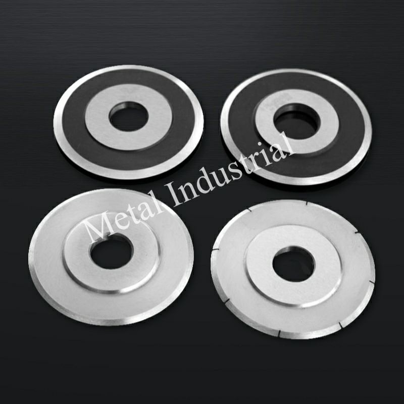
여러 슬리팅 라인에서 툴링을 표준화하는 공장을 위해, Maxtor Metal은 배치(Batch)별 완벽한 치수 및 경도 품질 보증서를 갖춘 전단용 원형 나이프(Circular shear knives)를 공급하며, 나이프가 기존 아버(Arbor) 및 홀더 도면과 일치해야 하는 경우 OEM/ODM 맞춤형 지원을 제공합니다. Maxtor Metal’s circular knives and blades for geometry and specification reference.
Ultimately, measuring the success of these stability controls comes down to key performance indicators. High-performing converting operations track five core KPIs to validate their slitting performance:
- Scrap & Waste Rate (%): Direct reduction in trimmed film waste and rejected off-spec rolls.
- 전체 장비 효율성(OEE): Higher running speeds and sustained cut stability.
- Unplanned Downtime: Fewer line stops caused by web breaks or mid-run adjustments.
- Blade Service Life: Extended tool durability resulting from minimized side loading and optimal overlap.
- Customer Quality Complaints: Lower incidence of edge weaves, telescoping, or slitting defects in finished roll shipments.
Author / Technical Reviewer
Jerry Chu | Technical Support Specialist (After-sales Service)
Maxtor Metal
Jerry brings 10+ years of cross-industry application experience across paper manufacturing, plastic recycling/crushing, metal slitting, and wood processing. Specializing in resolving real-world slitting challenges—such as cutting burrs, excessive dust, and edge instability—he works directly with field engineering teams to optimize tooling performance and operational reliability.
- 인증: Certified Maintenance & Reliability Professional (CMRP), Project Management Professional (PMP®)
- Specialties: On-site slitting troubleshooting, custom blade geometry design, and preventive maintenance SOP development

 English
  Spanish
  Italian
  French
  Portuguese
  Russian
  German
  Arabic
  Hindi
Hindi  Vietnamese
  Indonesian
  Japanese
  Korean