

Published: 2026-05-28 | Last updated: 2026-05-28
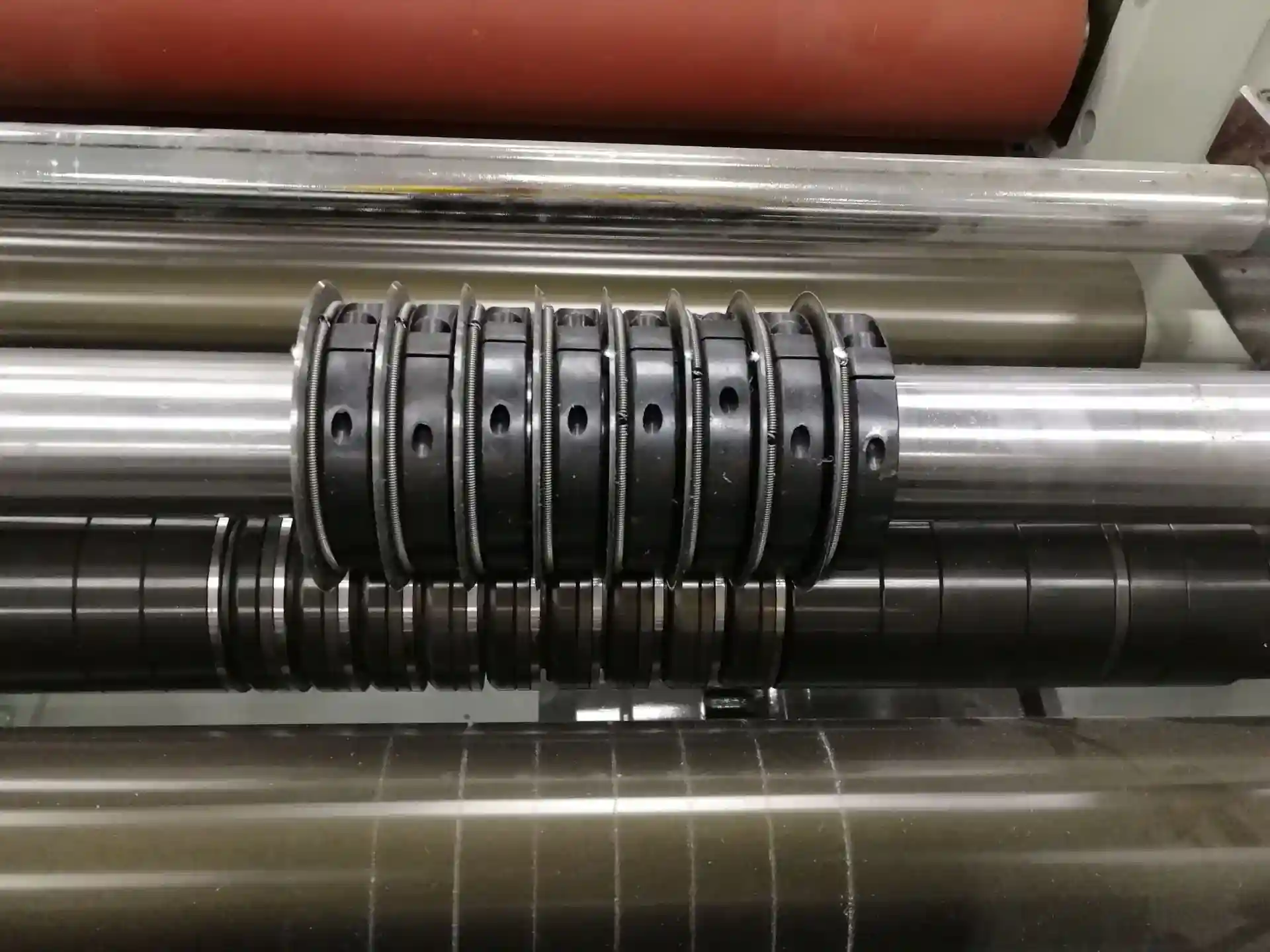
If you’re chasing cleaner edges, less dusting, and longer knife life on a slitter/rewinder, Maxtor Metal sees the same pattern again and again: the fastest wins often come from two setup variables you can actually control—overlap depth E side clearance.
- Define overlap depth and side clearance as primary levers in shear and crush cutting.
- Link settings to edge quality, force/torque, temperature, wear, and OEE/TCO.
- Preview a computational workflow to optimize within material and machine constraints.
- Engineering Note: For knife-level specifications, including axial runout standards and material grades, see Maxtor Metal’s Precision Circular Slitter Knives.
In shear slitting, overlap depth and side clearance jointly create (or destroy) a stable cut point. In crush/score cutting, the equivalent “depth” is penetration into the anvil and the “clearance” becomes alignment and pressure uniformity. Either way, these settings show up in the KPIs plants care about: edge quality, load/torque, heat, wear rate, changeover frequency, and ultimately OEE and total cost of ownership.
This article lays out a practical workflow: start with mechanics, verify with measurement, then use DOE + a Pareto lens to find a robust operating window that fits your material and machine limits.
If you’re troubleshooting today, treat it like a slitting knife setup burrs heat wear problem: get edge, load, and temperature signals on the same run, then adjust overlap and clearance in small, documented steps.
Mechanics and definitions
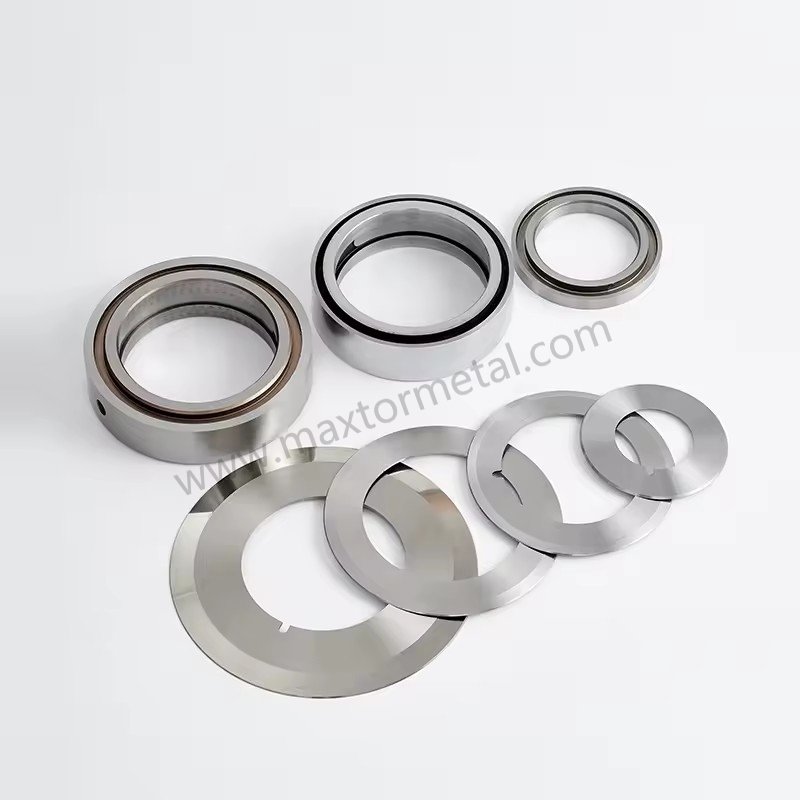
A practical way to think about shear slitting overlap depth E circular knife side clearance is that overlap sets the cut point geometry, while clearance (and the resulting side load) determines how stable that cut point stays at speed.
Overlap depth
In shear slitting, overlap depth is the vertical intersection that ensures the knives form a true cut point. In experimental studies of shear-slitting, cutting geometry(and edge support level) and related parameters (including clearance) are shown to influence cut-surface formation and edge defects such as burr formation [1].
Practically, overlap depth is a trade-off:
- Too little overlap can let the cut point “open,” pushing the web into rubbing/sawing behavior and unstable separation.
- Too much overlap increases the contact path and rubbing, which can raise cutting load and heat and accelerate edge wear; temperature and contact conditions are well-known drivers of friction and wear behavior in tribological systems [2].
In crush/score cutting, the same risk shows up as over-penetration: you don’t have knife-to-knife overlap, but you can still drive unnecessary compression, heat, and wear if penetration/nip is excessive. When teams compare crush cutting vs shear cutting settings, the common mistake is trying to run crush/score with shear-like “more overlap” thinking—pressure and alignment become the dominant levers.
Side clearance and side load
Side clearance is the axial/lateral relationship between the upper and lower knives (or holder and mating element) that determines how the knives stay engaged under dynamic load.
- If clearance/side engagement is too large, the web can bend or stretch locally before it fractures, which often appears as burrs, ragged edges, and unstable slit widths.
To widen the practical operating window on demanding webs, Maxtor Metal can also recommend material upgrades (for example, powder-metallurgy tool steels) and edge-prep choices based on your substrate and failure mode—then validate the result in your line’s actual clearance and runout conditions.
- If clearance is too tight, you get micro-rubbing and metal-to-metal contact—one of the fastest ways to create heat spikes and micro-chipping.
For high-speed converting, it helps to think of side clearance in two layers:
- Geometric clearance (what you set in the stack-up)
- Effective clearance under load (what actually happens once runout, holder compliance, and thermal growth enter the picture)
Conclusione chiave: Overlap creates the cut point; side clearance controls how stable that cut point remains under speed, tension changes, and runout.
Force, heat, wear coupling
Overlap depth and side clearance don’t just affect edge appearance—they change the physics of the cut.
- Force/torque rises when overlap is excessive or when clearance is too tight, because the contact length and rubbing increase.
- Temperatura follows force. More friction and plastic deformation mean more localized heating at the edge.
- Wear accelerates with heat and side load. As a general tribology principle, friction and wear depend strongly on contact pressure, sliding speed, and temperature; sustained high contact temperature can accelerate wear mechanisms and degrade edge stability [2].
The coupling is why “it still cuts” isn’t a safe stopping point. A setup that cuts today but runs hot will usually pay you back with faster dulling, more dusting, and more unplanned downtime next week.
Practical starting windows
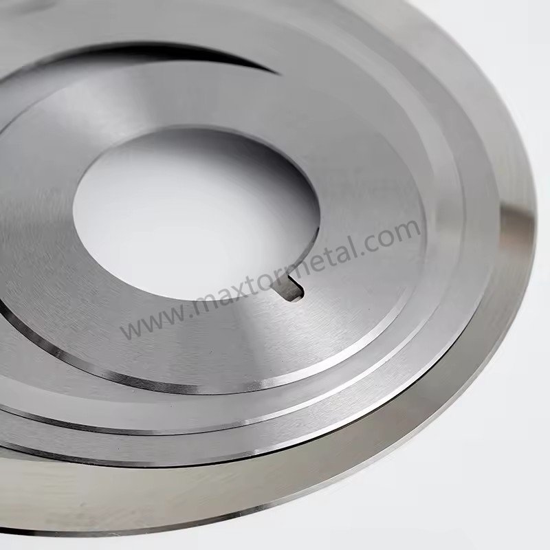
The safest approach is to treat any numeric values as starting windows, then verify with measurement and edge-quality checks at real line speed.
Where available, Maxtor Metal publishes application-dependent starting windows on the coltelli e lame circolari product page, overlap depth is described as a vertical intersection depth window of 0.5–1.5 mm, and axial side clearance for harder substrates (e.g., metallic foils/hard polymers) is stated as 0.002–0.01 mm. Use these as initial bounds—not as universal rules—then tighten the window based on your material and machine behavior.
Films and laminates
Start conservative and tune with edge inspection:
- Overlap depth: start low and increase in small steps until the edge is continuously clean (no tearing, no intermittent separation).
- Side clearance/side load: use the minimum engagement that keeps the cut stable without audible rubbing or abnormal temperature rise.
Typical symptom-based tuning:
- If you see edge tearing, intermittent uncut strands, or wandering slit lines, overlap or engagement may be too low.
- If you see melted-looking edges, edge glossing, or smell/heat around the knife, overlap/engagement is likely too high or alignment is forcing rubbing.
Paper and paperboard
Paper is often more forgiving on “will it cut” and less forgiving on “how long will the knives last.” One useful reference pattern (even though it’s a blade/band context) is Valmet’s warning that too little overlap can cause the blade to ride up and dull, while too much overlap dulls prematurely and can damage the web in its slitter adjustment guidance.
Practical setup intent:
- Keep overlap just high enough that you don’t see ride-up or intermittent cutting under normal tension variation.
- Keep side load as light as possible while maintaining a stable cut.
Nonwovens and textiles
With fibrous webs, “clean edge” is often about controlling fiber pull and fuzz.
- Overlap depth: increase only until fiber pull stops; beyond that, you typically trade fuzz for heat and faster edge rounding.
- Side clearance/side load: avoid over-loading that crushes the web edge and increases lint generation.
For thin films and nonwovens where a fixed clearance is difficult to hold, a spring-loaded zero-clearance holder approach can maintain consistent contact as conditions change; see Sistema a molla per taglio a cesoia a gioco zero.
A good discipline is to verify at production speed with your actual web tension window, because low-speed trials can hide fiber pull that appears once the web dynamics change.
Measurement and instrumentation
If you can’t measure overlap and clearance reliably, you can’t optimize them. The goal is to convert “feel” into numbers you can trend and control.
Verifying overlap and clearance
Minimum measurement set:
- Overlap verification method appropriate to your holder design (gauge/chord method, dial indicator reference, or calibrated stops).
- Axial runout checks on knives and tooling stack-up. Poor runout can make overlap and clearance oscillate each revolution, which shows up as periodic edge defects.
- Alignment checks (knife squareness, holder parallelism, shaft-to-shaft alignment).
For spacer stack-up control methodology, see our companion guide on Gestione della tolleranza cumulativa dello spessore.
Where Maxtor Metal’s QC processes are relevant: tight runout and thickness/flatness control on the knife itself reduces one major source of “mystery variability.” The product page describes laser interferometric axial runout verification and controlled grinding/finishing steps—useful when you’re building a setup that must hold a narrow window over long runs.
Force/torque and temperature sensing
You don’t need a lab to get meaningful signals. Aim for trends:
- Torque/drive current trending: rising torque at constant speed and tension is often your earliest sign that overlap/clearance has drifted or the edge has rounded.
- Temperature checks: use an IR spot check or thermal camera at steady state to compare setups. Heat is a proxy for friction and plastic work.
Control variable rule:
- Keep tension, speed, and web path stable during tests. Otherwise, you’ll attribute a tension change to an overlap change.
Edge quality metrology
Pick edge metrics your plant can measure consistently:
- Burr / feathering severity (simple graded scale with photo standards)
- Dusting / lint rate (collection filter mass over a fixed run, or housekeeping burden tracking)
- Microscope snapshots at fixed magnification (same lighting and angle)
- Downstream defect rate tied to the slit edge (wrinkling, blocking, unwind issues)
The point is not perfection—it’s repeatability. The same test, the same lighting, the same pass/fail rules.
The optimization model
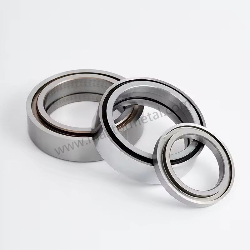
Once mechanics are stable and measurement is in place, you can optimize overlap depth and side clearance like any other process window problem.
DOE to map the design space
A practical DOE for converting looks like:
- Factors: overlap depth, side clearance/side load, speed (optional), tension (optional), knife condition (new vs mid-life).
- Responses: edge quality score, torque/current, temperature rise, dusting proxy, changeover time.
Keep it tight:
- Use a small factorial or central composite design to cover the space without exploding trials.
- Randomize run order where feasible to reduce drift bias.
Surrogate modeling (RSM/GP)
The goal of a surrogate model is to predict responses between tested points.
- Response surface methods (RSM) are simple and interpretable. They work well when the response is smooth.
- Gaussian process (GP) models are more flexible when you suspect nonlinearities (common in cutting due to threshold effects).
You don’t need to publish the math to get value. What you need is a model that helps answer: “If I move overlap down slightly and open clearance slightly, will I still meet edge spec without overheating?”
Multi-objective Pareto trade-offs
In the real world you’re balancing at least two objectives:
- maximize edge quality
- minimize load/temperature (proxy for wear and downtime risk)
Use a Pareto view to pick operating points that aren’t dominated by another setting.
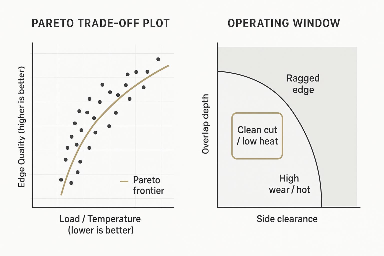
Worked example (illustrative, not universal)
Below is a simplified example of how a team might translate the workflow into an actionable setup window. Numbers are intentionally generic—use your own machine limits and material specs.
Scenario
- Line: high-speed slitter/rewinder
- Web: film or paper-grade web where edge defects show up as burr/feathering and dusting
- Objective: meet edge spec while minimizing drive load and temperature (proxy for wear)
Step1 — Choose starting bounds
- Start within your documented safe setup limits.
- Use published starting windows (when available) only as bounds, then narrow them based on your machine’s runout, holder stiffness, and the substrate’s behavior.
Step2 — Define what you will measure on every trial
- Edge quality score (use a consistent rubric)
- Drive current/torque at steady state
- Temperature rise at the knife area (IR spot check or thermal camera)
- Notes on dusting/lint and any audible rubbing
Step3 — Run a small 2×2 DOE (fast learning with minimal trials)
Choose two levels for each factor and keep speed/tension fixed during the trial block.
- Factor A: overlap depth → Low / High
- Factor B: side clearance (or controlled side load) → Low / High
Record responses after the process stabilizes at the same time-in-run.
Step 4 — Pick a Pareto-balanced point
- Eliminate any settings that fail the edge spec.
- Among the remaining settings, prefer points with lower torque/current and lower temperature rise.
Step 5 — Validate robustness
- Recheck the chosen point at the top and bottom of your real tension window.
- Repeat with a mid-life knife condition to ensure the window holds as the edge rounds.
The takeaway is not the specific numbers—it’s the discipline: small, controlled changes + repeatable measurements + a documented decision rule.
Quantified field case (paper converting, anonymized)
The following data comes from Maxtor Metal project support for an anonymized paper manufacturer. The customer name has been anonymized.
Context
- Industry: paper converting / rewinding line for coated printing paper
- Material: lightweight coated paper (LWC) for packaging inserts and labels
- Basis weight: 60–90 g/m²
- Thickness: ~55–95 μm
- Surface and fillers: clay-coated surface; calcium carbonate filler
- Notes: abrasive dust generation at higher speed; sensitive to edge fuzz and fiber pull-out
- Equipment: duplex rewinder with a shear slitting section
- Trial speed range: 900–1400 m/min (max line speed 1800 m/min)
- Knife holders: pneumatic shear knife holders; dished top knives + bottom anvils
- Web tension: 80–140 N (varies with roll diameter)
Initial symptoms and baseline scoring
At speeds above 1200 m/min, the line showed paper dust accumulation, fuzzy slit edges, occasional feathering, and unstable knife life between shifts.
Operator scoring system (1–10 severity):
- Dust generation: 8/10
- Edge fuzz: 7/10
- Cut stability: 6/10
Note on method: There is no single, universally adopted ISO/TAPPI/ASTM standard that mandates a 1–10 severity score for slitting defects. In practice, plants commonly use a documented internal visual severity scale (with training and reference photos) and, where needed, cross-check it against standardized test methods. For paper cut-edge raggedness, ISO 22414 (Paper — Cut-size office paper — Measurement of edge quality) provides a repeatable, template-based ordinal edge-quality rating approach that can be used as a reference framework when defining severity anchors for fuzz/feathering.
A previous attempt increased overlap aggressively to reduce fuzz, but it increased heat generation and accelerated knife wear in less than one production shift.
Settings before and after
Original settings
- Overlap: 0.9–1.1 mm
- Side clearance / side load: relatively high pneumatic loading (estimated 5–6 lbf equivalent contact pressure)
Observed issues during long runs: excessive friction, polished/glazed knife edge, and rising dust generation.
Optimized settings (after multiple production trials)
- Overlap reduced to: 0.45–0.65 mm
- Side clearance / side load adjusted to a lighter, more stable contact condition
- Cant angle slightly reduced
- Bottom knife overspeed stabilized at ~5%
Risultati
| Metrico | Before optimization | After optimization |
|---|---|---|
| Edge quality severity score | 7/10 | 2–3/10 |
| Dust severity score | 8/10 | 3/10 |
| Scrap / rejected rolls | 4–6% | 1.5–2.5% |
| Knife change frequency | every 1–2 shifts | every 3–4 shifts |
| Average knife life | baseline | +40–60% |
| Unplanned slitting stops | frequent during long runs | reduced by ~50% |
Conditions behind the data
- Knives reground and polished before trials
- Holder bearings verified before setup
- Stable web tension control
- Spacer/contact surfaces cleaned each shift
- Measurements compared only after thermal stabilization of the slitting section
Constraints and robustness
Material variability and abrasion
Your “optimal” point can fail when the material changes.
Common variability sources:
- thickness and coating variability
- filler/abrasive content (wear rate changes)
- humidity and static effects that change web behavior
Robustness tactics:
- Validate at the upper and lower bounds of your real material spec.
- Track knife life by material lot when abrasion is high.
Machine limits and alignment
You can’t optimize past mechanical limits.
Constraints to document explicitly:
- maximum achievable alignment/runout
- holder stiffness and repeatability
- safe side load limits for bearings and shafts
If your runout is large, the model will “recommend” a wider clearance just to survive oscillation. Fix the mechanical root cause first.
For a detailed treatment of runout measurement and cold-to-hot verification, see our companion guide on Axial Runout and Edge Quality.
For the bore-level root cause—how ISO 286 fit selection and bore-to-OD coaxiality control translate into assembled TIR—see Tolleranza e concentricità del foro centrale: ottimizzazione degli accoppiamenti ISO 286 per lame da taglio ad alta velocità.
Wear, drift, and control plans
Optimization isn’t a one-time event. Overlap and clearance drift with wear, thermal growth, and rebuilds.
Control plan elements:
- baseline settings for new knives and mid-life knives
- re-check triggers (torque trend threshold, temperature threshold, edge-score drop)
- inspection frequency and sign-off roles
This is also where supplier process control matters. Maxtor Metal positions its circular knives around strict in-process checks (incoming material inspection, first article, in-process, final inspection) and measurable verification such as runout checks and hardness mapping. Shipping documentation and customs coordination support is available for international orders, which reduces the risk of late replacements disrupting production schedules.
Deployment checklist
Pre-DOE calibration
- Confirm knife condition and geometry are within spec (no chips, consistent bevel).
- Verify alignment and runout; document the measurement method.
- Lock down “constant” variables (web path, tension window, speed band) for the DOE.
During-DOE controls
- Change only the planned factors; record the actual achieved settings.
- Use the same edge inspection method and scoring rubric each run.
- Capture torque/current and temperature at the same time-in-run (steady state).
Post-DOE SOP and monitoring
- Publish the chosen overlap/clearance operating window (min/target/max).
- Define drift triggers (torque rise, temperature rise, edge-score drop) and actions.
- Build a changeover checklist so settings are repeatable across shifts.
Applicability and limits (when to validate more carefully)
The workflow in this article is intended for rotary knife slitting where overlap and side clearance can be measured and controlled. In the following conditions, validate more conservatively and resolve upstream issues before you “tune overlap”:
- Ultra-thin or low-stiffness webs: increased risk of wrinkling, stretching, and unstable slit width. Reduce the trial step size, confirm tension control, and validate at production speed.
- High filler / abrasive grades: accelerated edge wear can shift the operating window quickly. Monitor torque and temperature trends more frequently and track knife life by material lot.
- Static electricity and humidity-driven variability: dusting, lint, and web handling can change day-to-day. Stabilize humidity control and static mitigation before attributing defects to overlap/clearance.
- High radial/axial runout or poor alignment: overlap and clearance may oscillate each revolution, causing periodic defects. Correct runout/alignment first; otherwise DOE results may not generalize.
If these limits apply, treat any “optimal” setting as provisional until it holds across your full tension and speed window.
Safety note (read before adjusting knives)
Slitting and knife setup can be hazardous. Follow your site’s procedures and the machine manufacturer’s guidelines.
- Utilizzo lockout/tagout (LOTO) before any adjustment, inspection, or cleaning.
- Wear appropriate PPE (cut-resistant gloves, eye protection, and other site-required protection).
- Treat knives, holders, and nearby components as potential hot surfaces after running; verify temperature before handling.
- Keep hands clear of pinch points and rotating parts on slitter/rewinder systems; never reach into the web path while the line is energized.
- Do not exceed the machine’s allowable limits for overlap/penetration, side load, or pressure. When in doubt, start at the low end of your window and validate step-by-step.
This article provides general engineering guidance; validate final settings on your equipment and material.
Conclusione
Optimal overlap depth and side clearance don’t just “improve the edge”—they stabilize the whole slitting system: lower heat, slower wear, fewer web breaks, and fewer unplanned changeovers. When you treat these settings as measurable variables, and use DOE plus a Pareto trade-off to choose a robust operating window, you can move faster with less scrap and less downtime.
If you want repeatable results across shifts and plants, Maxtor Metal recommends keeping the workflow simple: verify the knives and tooling (runout, hardness consistency, documented inspections), then use a control plan to catch drift early.
The quickest path to adoption is simple: validate the starting windows on representative materials at real speed/tension, then monitor torque and temperature trends to keep the setup inside the window as knives wear.
FAQ
Domanda: Cos'è la profondità di sovrapposizione nel taglio a cesoia?
Risposta: La profondità di sovrapposizione indica quanto la lama circolare superiore si interseca al di sotto della tangente della lama inferiore nel punto di taglio. Una sovrapposizione insufficiente può aprire il punto di taglio e causare una separazione instabile; una sovrapposizione eccessiva aumenta la lunghezza di contatto e l'attrito.
Domanda: Cos'è il gioco laterale in una taglierina a lame circolari?
Risposta: Il gioco laterale è lo spazio assiale/laterale (o innesto effettivo) tra le lame superiore e inferiore che determina il modo in cui le lame rimangono innestate sotto carico. Un gioco eccessivo può portare a flessione/allungamento sul filo e a bave; un gioco insufficiente può causare sfregamento, calore e micro-scheggiature.
Domanda: Come faccio a sapere se la profondità di sovrapposizione è troppo alta o troppo bassa?
Risposta: Una sovrapposizione troppo bassa si manifesta spesso con una separazione incompleta, strappi o difetti intermittenti sul filo. Una sovrapposizione troppo alta è solitamente indicata da un'usura più rapida del filo, maggiore calore sulla lama e, a volte, distorsione del nastro (web) o formazione di polvere.
Domanda: Perché un gioco più stretto a volte peggiora la qualità del tagliente?
Risposta: Perché un gioco troppo ridotto può forzare lo sfregamento metallo-metallo e aumentare la temperatura. Tale calore accelera l'usura e può creare micro-scheggiature, producendo un filo più irregolare nonostante le lame siano "più vicine".
Domanda: Con quale profondità di sovrapposizione e gioco dovrei iniziare per il taglio di film?
Risposta: Iniziate con una sovrapposizione conservativa e il gioco laterale minimo che mantenga il taglio stabile, quindi regolate a piccoli incrementi ispezionando il filo alla velocità di produzione. Il range esatto dipende dallo spessore, dal tipo di polimero, dai rivestimenti e dalla rigidità della macchina.
For adhesive-backed films where coating build-up on knife faces shifts the effective clearance over a run, surface coating selection interacts directly with your clearance window. A diagnostic framework for choosing between DLC and PTFE coatings based on whether your failure mode is wear-limited or transfer-limited is covered in DLC vs PTFE Coatings for Slitting Blades: Engineer’s Guide.
Domanda: Quali sono le misurazioni più importanti per ottimizzare le impostazioni delle lame circolari?
Risposta: I segnali più pratici sono la valutazione della qualità del filo, le tendenze della coppia/corrente di azionamento, i controlli della temperatura e la verifica del runout/allineamento. Se si riesce a monitorare questi quattro parametri, di solito è possibile rilevare le derive prima che aumentino drasticamente gli scarti e i tempi di fermo macchina.
Domanda: In che modo il DOE e l'ottimizzazione di Pareto aiutano nell'impostazione del taglio?
Risposta: Il DOE (Design of Experiments) mappa come la sovrapposizione e il gioco influenzano la qualità del tagliente, la coppia e la temperatura in un intervallo definito. L'analisi di Pareto aiuta quindi a scegliere impostazioni che migliorano la qualità del filo senza sacrificare eccessivamente la durata a causa di calore e usura.
Domanda: Dove posso trovare lame circolari progettate per la lavorazione di film, carta e tessuto non tessuto?
Risposta: La pagina dei prodotti di lame e coltelli circolari di Maxtor Metal riassume le applicazioni comuni, le opzioni dei materiali e i metodi di verifica della qualità, fondamentali quando si cerca di mantenere un ristretto intervallo operativo.
Jerry Chu è un Specialista di supporto tecnico in Maxtor Metal’s Servizio post-vendita team, with 10 years of cross-industry application experience spanning paper converting, plastic recycling/granulation, metal slitting, and wood processing. He helps plants troubleshoot real-world slitting issues such as cutting burrs, excessive dusting, and shortened knife life through setup validation, measurement discipline, and practical process windows.
Certificazioni: PMP, CMRP
At the end of the day, stable slitting is controlled geometry plus controlled verification—exactly the mindset Maxtor Metal builds into both knife manufacturing and the supporting documentation you need for traceability.
Riferimenti bibliografici
[1] “Experimental Research on Sheared Edge Formation in the Shear-Slitting Process.” PMC (peer-reviewed, open access). https://pmc.ncbi.nlm.nih.gov/articles/PMC9784500/
[2] Khonsari, M. M., & Booser, E. R. Applied Tribology: Bearing Design and Lubrication. Wiley.
[3] ISO 22414. Paper — Cut-size office paper — Measurement of edge quality. https://www.iso.org/standard/82031.html
[4] ISO 15359. Paper and board — Determination of coefficient of friction. https://www.iso.org/standard/27374.html
[5] TAPPI T 494. Tensile properties of paper and paperboard (using constant rate of elongation). https://imisrise.tappi.org/TAPPI/Products/01/T/0104T494.aspx
[6] TAPPI T 411. Thickness (caliper of paper, paperboard, and combined board), Test Method. https://imisrise.tappi.org/TAPPI/Products/01/T/0104T411.aspx
[7] ASTM D828. Standard Test Method for Tensile Properties of Paper and Paperboard. https://www.astm.org/d0828-16e01.html

 English
  Spanish
  Italian
  French
  Portuguese
  Russian
  German
  Arabic
  Hindi
Hindi  Vietnamese
  Indonesian
  Japanese
  Korean