

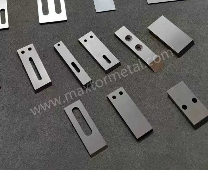
Respuesta rápida: El corte estable en la cara de la matriz en las líneas de peletización bajo agua depende de la combinación de cuatro variables: el grado de carburo (HRA 88–92 para la mayoría de los insertos de WC-Co), la geometría del filo (radio controlado, no solo "afilado"), la gestión de la presión de contacto (acoplar → ajustar, no perseguir la presión) y la estabilidad del circuito de agua (40–60 °C, filtrada, desgasificada). Cambiar los insertos sin abordar el estado de la cara de la matriz o el equilibrio del cabezal de corte es la razón más común por la que las actualizaciones de carburo no rinden lo esperado.
En la peletización de cara de matriz, un inserto de carburo de tungsteno es un elemento de corte de WC-Co sinterizado e introducido por soldadura fuerte en un bloque de soporte de acero, diseñado para mantener un filo de corte estable contra la cara de una matriz giratoria a velocidades de 1,000 a 4,000 RPM en el procesamiento continuo de polímeros.
Las líneas de producción a gran escala de LDPE y PP no pierden tiempo de actividad porque una cuchilla se desgaste, sino porque el corte se vuelve inestable: se acumulan partículas finas, aparecen residuos, los amperios varían y los operarios empiezan a ajustar la configuración.
Esta guía está escrita para sistemas de corte en la cara de la matriz (peletizadoras bajo agua y de anillo líquido) donde pequeños cambios en el grado del inserto, la geometría del filo, la presión de contacto y el control del circuito de agua pueden decidir si la línea opera durante semanas o si se detiene esta misma noche.
Página de producto de Maxtor Metal para cuchillas de peletizadora de plástico Abarca toda la gama de formatos, dimensiones y tolerancias de cuchillas utilizadas en los sistemas de troquelado, lo que constituye una referencia útil para unificar la terminología entre operaciones, mantenimiento y adquisiciones.
- Público objetivo: Unidades de megaproducción de LDPE/PP que utilizan peletizadoras subacuáticas/de anillo de agua.
- Objetivos: maximizar el tiempo de actividad, estabilizar la calidad de los pellets, reducir las partículas finas y los residuos.
- Contenido de esta guía: materiales HRA 88–92, diseño, controles, circuito de agua, KPI.
Grados de WC-Co y dureza
Los carburos cementados para cuchillas de inserción suelen ser de carburo de tungsteno (WC) con un aglutinante de cobalto (WC-Co). En la práctica, la elección del grado implica un equilibrio entre dureza (resistencia al desgaste) y tenacidad (resistencia al astillamiento), y el punto óptimo depende de la abrasividad de la resina, el contenido de relleno y la estabilidad del control de contacto.
La dureza se especifica comúnmente en la escala Rockwell A (HRA) para el carburo cementado; el método de ensayo y las definiciones de la escala están estandarizados. Para los carburos cementados específicamente, ASTM B294 — Ensayo de dureza de carburos cementados define los procedimientos de prueba Rockwell HRA (indentador de diamante, fuerza preliminar de 10 kgf, fuerza de prueba total de 60 kgf) y hace referencia al método Rockwell más amplio en ASTM E18 — Dureza Rockwell de materiales metálicos. Muchos laboratorios también alinean las prácticas de Rockwell con ISO 6508 (dureza Rockwell)) para lograr coherencia entre diferentes estándares.
Para el control de la fabricación, combine un rango de dureza con una expectativa de microestructura (tamaño de grano y porosidad), ya que dos insertos pueden medir la misma HRA y aun así comportarse de manera diferente en el borde.
Si está armonizando los términos entre equipos, la guía de Maxtor Metal sobre Ajuste de la presión de la cuchilla de la peletizadora y protección del troquel Es una referencia complementaria útil porque relaciona los defectos de corte con ajustes controlables (presión, protección del troquel y ventanas de operación).
Ventana de inserción de carburo de tungsteno
Una ventana práctica a la que apuntan muchas plantas para los insertos de corte de la cara del troquel es HRA 88–92. Es ancho a propósito:
- Extremo inferior (≈88–89 HRA): mayor aglutinante/resistencia, a menudo más seguro cuando el control de contacto es imperfecto, se producen roces al arrancar o la superficie del chip no es perfectamente plana.
- Gama alta (≈91–92 HRA): mayor resistencia al desgaste, a menudo útil al usar compuestos abrasivos o al mantener una separación casi nula sin picos de presión.
Qué verificar más allá de “HRA en el certificado”:
- Clasificación del tamaño del grano y la porosidad En el caso del carburo sinterizado, debido a que los granos gruesos y la mayor porosidad aumentan el riesgo de astillamiento de los bordes en caso de contacto intermitente.
- Consistencia lote a lote (Una misma designación de grado no siempre implica la misma microestructura entre diferentes proveedores).
Si tiene que escribir una especificación: haga referencia al lenguaje de clasificación de metales duros reconocido (muchos proveedores se corresponden con las agrupaciones de aplicaciones ISO; consulte Grupos de aplicaciones de metales duros ISO 513) y luego defina las pruebas de aceptación que sean importantes para su modo de fallo.
Radio y acabado del borde
En el corte subacuático, el filo no es una navaja por mucho tiempo; es un filo de trabajo que debe mantenerse estable bajo refrigeración por agua, ciclos térmicos y roces ocasionales. Dos parámetros del filo suelen afectar la calidad del proyectil más rápido de lo esperado:
- radio del borde (los micrones importan): demasiado afilado y aumenta el riesgo de microdesprendimiento; demasiado romo y "empuja" el metal fundido, levantando colas y manchas. Esta compensación es consistente con la literatura más amplia sobre mecánica de corte: un borde preparado/redondeado puede mejorar la robustez contra el astillado, pero radios más grandes también pueden aumentar la fuerza de empuje a través de un arada efecto (ver Wyen y Wegener (2010), CIRP Annals — Influencia del radio del filo de corte en la integridad de la superficie).
- Terminar en el bordeLas marcas de rectificado y las rebabas son factores que inician grietas; además, interrumpen un corte uniforme en la zona de la matriz.
Un enfoque práctico consiste en tratar el radio del borde como una variable de proceso controlada:
- Defina un rango de radio de borde objetivo y mídalo (con un comparador óptico o un microscopio), no solo que esté "nítido".“
- Vincule las decisiones de remolienda a los parámetros de los pellets (partículas finas, residuos) en lugar de basarse únicamente en la inspección visual.
Recubrimientos para PP/PE cargado
En el caso de los concentrados de PP/PE y abrasivos con cargas, los recubrimientos pueden ser útiles al reducir la adhesión y ralentizar el desgaste abrasivo en el borde, pero solo funcionan si el borde base es estable.
Lo que importa desde el punto de vista operativo:
- Propósito del recubrimiento: antiadherencia vs resistencia a la abrasión vs resistencia a la corrosión.
- Modo de falloSi observa que el recubrimiento se descascara o se desprende en el borde prematuramente, es probable que tenga un problema con la preparación del borde o la presión de contacto antes de que se presente un problema de "recubrimiento defectuoso".
- Compatibilidad con material reciclado: decidir si los insertos recubiertos son desechables o re-recubiertos; incorporar eso al modelo de costos.
In short — materials and grade selection: HRA 88–92 is the starting spec, but grain size, porosity, and lot-to-lot consistency are what decide whether that number translates into stable edge life at the die face.
For lines where the wear mechanism is driven by glass-fiber loading rather than bulk abrasion — and where the blade material is PM stainless rather than cemented carbide — the parallel grade selection logic between M390 and CPM S90V is covered in our guide on powder metallurgy pelletizer blade selection under high glass-fiber wear.
Diseño de bloques compuestos
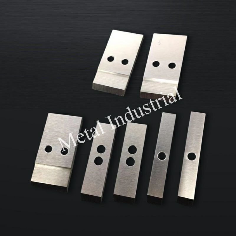
Las cuchillas de inserción rara vez fallan "porque el carburo es carburo". Fallan porque el conjunto compuesto no puede mantener el filo siguiendo la superficie de la matriz de forma consistente a lo largo del tiempo.
Soldadura fuerte e integridad de la junta
La junta de soldadura es un elemento estructural. Si se deforma, se agrieta o se distorsiona debido a los ciclos térmicos, el inserto puede permanecer duro y aun así cortar mal.
El proceso de control de calidad de Maxtor Metal para los conjuntos de bloques de cuchillas incluye la verificación del espacio de soldadura, la inspección de humectación y la medición de la planitud/desviación respecto a las tolerancias del plano, con secciones transversales de muestra como parte de la lista de verificación previa al lanzamiento.
Qué debes revisar en tu propio plan de aceptación:
- Selección de aleación de soldadura fuerte Adecuado para la temperatura de funcionamiento y el entorno corrosivo.
- Control de la separación de soldadura fuerte y evidencia de humectación completa (evitar huecos en la zona de borde de mayor tensión).
- Distorsión posterior a la soldadura: mida la planitud y la excentricidad en el bloque ensamblado, no solo en el inserto.
Rigidez y seguimiento del portador
La rigidez del portador es lo que convierte un punto de ajuste en una condición de contacto real y repetible.
Si el soporte se flexiona, la "presión" se convierte en una mezcla de la carga real en el borde más la vibración, y es la vibración la que produce partículas finas y colas intermitentes.
Cheques que suelen ser rentables:
- Verificar Asientos desde el centro de conexión hasta la aerolínea y el control del par de apriete (la repetibilidad es más importante que "lo suficientemente apretado").
- Medida carrera dinámica a velocidad de funcionamiento; la desviación estática por sí sola no refleja mucha información.
- Asegúrese de que el diseño del soporte mantenga la rigidez en todo el rango de temperaturas (la dilatación térmica puede alterar el seguimiento).
Equilibrar y barrer sobre los agujeros de la matriz
Un cabezal de corte puede estar "equilibrado" y aun así cortar de forma desigual si el barrido no cubre correctamente el patrón de orificios de la matriz.
Qué validar durante la puesta en marcha y después de un mantenimiento importante:
- Cobertura de barrido: confirme que la trayectoria de la cuchilla se superpone a todo el anillo de orificios de la matriz activa, incluidos los segmentos que estén bloqueados o enmascarados intencionalmente.
- Equilibrio a velocidad realEl desequilibrio aumenta la carga sobre los cojinetes, introduce vibraciones y obliga a los operarios a compensar con presión, lo que acelera el desgaste tanto de la cuchilla como de la matriz.
Para el cálculo completo del grado de equilibrio, los criterios de aceptación de excentricidad y la estructura del expediente de control de calidad que se aplican a los conjuntos de bloques de cuchillas a 1000–4000 RPM, consulte nuestra Marco de cualificación del bloque de cuchillas para peletizadoras de anillo de agua.
En resumen: la dureza del inserto depende directamente del conjunto que lo mantiene alineado con la cara del troquel; la integridad de la soldadura, la rigidez del soporte y el equilibrio dinámico son los factores clave para el buen funcionamiento del carburo.
Mapa de resolución rápida de problemas
Utilice esto como una ruta rápida de “síntoma → primeras comprobaciones → ajuste” antes de comenzar a cambiar la presión de la cuchilla.
- Las colas/cuerdas saltan repentinamente → verificar Estado de la superficie de la matriz (ranuras/puntos elevados), cabezal de corte sin, y estabilidad de la temperatura del agua → luego vuelve a comprobar patrón de contacto y presión de ajuste.
- Las multas aumentan gradualmente → verificar rendimiento de filtración, residuos recirculados y acabado/desgaste de los bordes → luego revisar objetivos de radio de borde y umbrales de re-molienda.
- La corriente del motor aumenta gradualmente a un ritmo constante. → correlacionar los amperios con la apariencia de los perdigones: aumento de amperios + perdigones de peor calidad generalmente significa frotamiento → confirmar la alineación y reducir el contacto después de la estabilización (enganchar → recortar).
- El inicio es inestable (congelación / colas / vibración) → priorizar equilibrio térmico (distribución de temperatura/flujo del circuito de agua, desgasificación) y superficies de asientos limpias → Solo entonces ajuste la velocidad/presión.
En resumen: las colas, las multas y los amperios apuntan cada uno a una causa raíz diferente; haga coincidir el síntoma con la comprobación correcta antes de tocar la presión.
Contacto y control
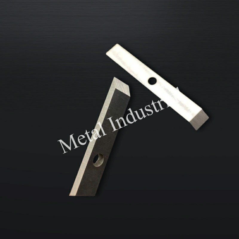
El control de contacto es donde convergen la calidad y el tiempo de actividad. Un corte estable generalmente se logra con un rango de operación estrecho: la fuerza suficiente para cortar limpiamente, pero no la suficiente para dañar la superficie de la matriz.
Presión y espacio casi nulo
Muchas plantas buscan una separación prácticamente nula (o un espacio muy reducido) con una presión de contacto controlada, porque es la forma más sencilla de mantener estable la longitud de los gránulos.
Para mantenerlo estable:
- Estrategia de participación → recorte: aplicar mayor fuerza para asentar y estabilizar, luego reducir la presión una vez que los pellets y los amperios se estabilicen.
- Mirar tendencia actual de los motores y la apariencia del perdigón; si la corriente aumenta mientras la calidad del perdigón se degrada, a menudo se está frotando en lugar de cortar.
Conclusión claveSi los operarios suelen "resolver" los problemas de las colas aumentando la presión de la cuchilla, a menudo se obtendrá calidad a corto plazo a costa de un ranurado rápido de la cara de la matriz.
Alineación y rodaje
Los problemas de alineación parecen defectos "misteriosos" en los gránulos porque se manifiestan como colas intermitentes, gemelos o picos finos.
El periodo de rodaje debe considerarse como una estabilización controlada, no como una prueba de fuego:
- Verifique que las superficies de los asientos estén limpias y que se les aplique un par de apriete uniforme y repetible.
- Realice un breve rodaje en condiciones controladas y, a continuación, vuelva a comprobar la excentricidad y el patrón de contacto.
- Si la superficie de la matriz presenta alguna ranura o protuberancia perceptible al tacto, corríjala antes de ajustar la configuración de la cuchilla. (El estado de la matriz influye en el comportamiento de la cuchilla tanto como el inserto).
Velocidad y frecuencia de corte
La frecuencia de corte es el vínculo entre el flujo del polímero y la geometría de los gránulos. Cuando cambia la velocidad, cambia:
- Distribución de la longitud de los pellets
- Generación de calor en el borde
- El “tiempo bajo carga” por pasada
Un enfoque de control práctico:
- Estabilice el rendimiento y luego ajuste la velocidad de corte para cumplir con las especificaciones del pellet.
- Si aumenta la velocidad para "corregir" las colas, verifique primero la causa raíz aguas arriba (viscosidad, temperatura de la boquilla, caudal de agua).
Para líneas de polímeros pegajosos, en particular TPU y EVA, donde la mala gestión de la presión de contacto es el principal desencadenante del pegajoso de la cuchilla y la acumulación de adhesión, el diagnóstico a nivel de mecanismo y la lógica de selección de recubrimiento DLC frente a PTFE se tratan en nuestra guía sobre detener la formación de goma en la peletización subacuática de TPU.
En resumen: un corte estable se consigue aplicando la fuerza suficiente para asentar la pieza limpiamente y luego recortando, no intentando corregir los defectos aumentando la presión.
Ingeniería del circuito de agua
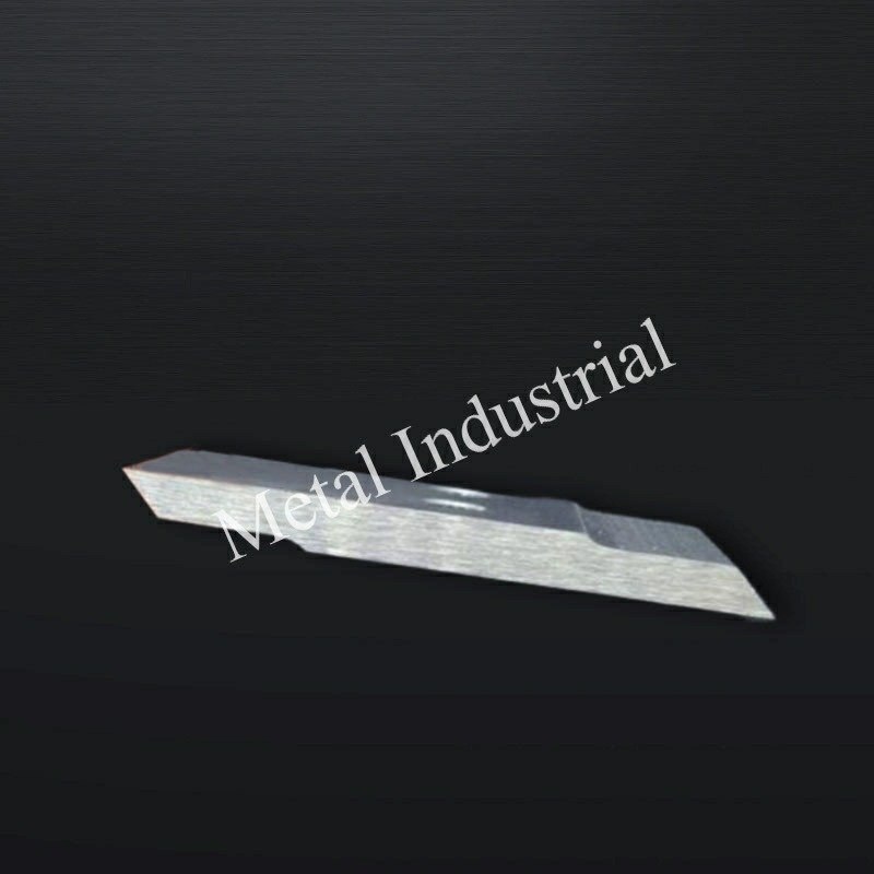
El circuito de agua no solo sirve para enfriar, sino que también es un sistema de estabilidad. La temperatura del agua, el caudal, la limpieza y los gases atrapados se reflejan en el punto de corte.
Temperatura y caudal
Una banda de control viable para muchas operaciones es 40–60°C temperatura del agua de proceso, ya que tiende a reducir el choque térmico al tiempo que evita que los gránulos se dispersen.
Qué gestionar en la práctica:
- La estabilidad de la temperatura supera a la temperatura absoluta.: un bucle a la deriva cambia el comportamiento de solidificación del polímero y puede parecer una cola "aleatoria".
- Distribución del flujo en la cara de la matrizLas zonas muertas crean riesgo de congelación localizada o sobrecalentamiento localizado.
Si observa inestabilidad al arrancar, a menudo se trata de un problema de equilibrio térmico. La investigación sobre la peletización de la cara de la matriz y la congelación destaca cómo las condiciones de transferencia de calor pueden provocar un corte irregular y residuos (ver Revista Internacional de Transferencia de Calor y Masa (2022), resumen del artículo). La guía práctica de resolución de problemas de Plastics Technology también enfatiza que la congelación del orificio de la matriz suele deberse a la secuencia de arranque, el calentamiento/aislamiento inadecuado de la matriz y las fluctuaciones del proceso; consulte Tecnología de plásticos: Evite la congelación de los orificios de la matriz..
Filtración y desgasificación
La filtración y la desgasificación son "variables ocultas" que determinan si la cuchilla y la matriz funcionan en agua limpia o en una suspensión.
- Filtración (protección gruesa + limpieza de corrientes laterales): Muchas plantas comienzan con una Colador/tamiz grueso para proteger las bombas y los sellos, entonces confíe en filtración de flujo lateral para eliminar de forma constante los sólidos en suspensión sin interrumpir el flujo principal. Para sistemas de agua de circuito cerrado, la guía de ChemAqua describe el uso de filtros progresivamente más finos durante la limpieza (por ejemplo, pasar de 50 µm a 20 µm y luego a 10 o 5 µm una vez que los filtros puedan permanecer en línea sin obstruirse) — ver ChemAqua: Opciones de filtración para sistemas de circuito cerrado.
- DesgasificaciónElimina el aire atrapado que puede causar cavitación, flujo inestable y enfriamiento inconsistente en la superficie de la matriz.
Señales operativas de que el filtro o la desgasificación son insuficientes:
- Las multas aumentan gradualmente sin que se observe ningún cambio geométrico evidente.
- Indicaciones de flujo inestable a velocidad constante de la bomba.
- Pulido rápido de los bordes/pérdida de acabado incluso con presión estable
Estabilidad térmica y secado
Un corte estable es solo una parte de la historia; también se necesita una gestión estable del flujo posterior.
- Mantenga un control de bucle lo suficientemente estricto como para que la humedad de la superficie de los pellets sea predecible.
- Si el rendimiento del secado fluctúa, no culpe únicamente a las secadoras; verifique primero la estabilidad de la temperatura del agua y la desgasificación.
En resumen: la estabilidad de la temperatura del agua, la filtración y la desgasificación son variables del proceso, no tareas de mantenimiento; las fluctuaciones en las condiciones del circuito se manifiestan como defectos en los pellets antes de que se reflejen en los manómetros.
KPI y ROI
Un programa de cuchillos se vuelve escalable cuando se traduce la sensación de "afilado" en indicadores clave de rendimiento (KPI) que predicen el fallo. antes baja la calidad.
¿Qué cambia primero cuando modificas las inserciones o la configuración?
La tabla que aparece a continuación es un "mapa direccional" práctico que los equipos utilizan para predecir qué se moverá cuando se cambie la pendiente, la preparación de los bordes o la estrategia de contacto.
Condiciones de contorno: Estos son típico Tendencias en el corte de la superficie de la matriz en líneas de PE/PP. Los resultados reales dependen de la abrasividad de la resina/carga, el estado de la superficie de la matriz, la rigidez/excentricidad del cubo y la estabilidad del circuito de agua. Valide en su línea y documente el rango de operación.
| Cambio que haces | Efecto típico sobre las multas | Efecto típico en colas/largueros | Qué observar desde el punto de vista operativo | Riesgo si se le presiona demasiado |
|---|---|---|---|---|
| Inserto de mayor dureza/mayor resistencia al desgaste (dentro de una familia de grados estable). | A menudo disminuye con el tiempo (desgaste más lento) | A menudo ↓ si el borde permanece estable | Microdesgaste y vibración en el borde de la vía | Puede aumentar el ranurado de la cara del troquel si el control de contacto es deficiente. |
| Borde más afilado / radio de borde más pequeño | Puede ↓ inicialmente | Puede ↓ inicialmente (corte más limpio) | Monitorear aumentos repentinos en las multas (microchips) | Mayor riesgo de astillamiento durante eventos de frotamiento/arranque |
| Mayor radio de borde / mayor preparación del borde | Puede ↑ si el borde comienza a “empujar” fundirse | Puede ↑ (más manchas/colas) | Busque manchas de bolitas y aumento de corriente | La preparación excesiva se comporta como un borde desgastado. |
| Estrategia de alta presión (solución de defectos mediante la aplicación de fuerza) | Mixto; puede disimular el desgaste brevemente. | Puede ↓ corto plazo | Mira las tendencias de los amplificadores y el uso de la cara mordida | Acelera el desgaste de la matriz; puede acortar la vida útil del inserto. |
| Estrategia de ajuste (ajustar, estabilizar y luego reducir) | A menudo ↓ (menos frotamiento) | A menudo ↓ (cizallamiento más estable) | Utilice las métricas de pellets y la corriente eléctrica conjuntamente. | Requiere un control de par/excentricidad repetible. |
Caso de ingeniería anónimo (PP relleno de CaCO₃ abrasivo)
Para concretar el debate sobre "inserción frente a control de procesos", aquí presentamos una comparación de campo anónima de una línea continua de peletización submarina que procesa un compuesto abrasivo.
Nota: Este ejemplo se basa en patrones típicos observados en programas de cuchillas para peletizadoras; no se trata del registro de inspección de un solo cliente. Los resultados operativos variarán según la resina, el contenido de relleno, el estado de la boquilla y la madurez del control del proceso.
Material y rango de operación (mantenidos constantes): homopolímero de PP con 25 wt% CaCO₃ (+0,5–1,0% coadyuvante de procesamiento), 7,5–8,5 t/h, MFI 8–12 g/10 min; velocidad de corte 2700–3100 rpm; agua de proceso 55–65°C; ~850 Agujeros de troquel; funcionamiento 24/7.
Diseño de la prueba: La planta reemplazó una cuchilla convencional de acero para herramientas endurecido con un filo de corte insertado de carburo de tungsteno mientras sostenía geometría de la cuchilla, punto de ajuste de la presión de la cuchilla, velocidad de corte, placa de troquelado, operarios y receta constante. El reemplazo se activó cuando Las multas superaron 1 wt% o Las colas superaron 0,5% (no es un intervalo de tiempo fijo).
Resultados observados (16 semanas, 12 campañas, ~3250 t procesadas, 96 muestras de pellets, 14 juegos de cuchillas):
- Multas: 1,35 wt% → 0,46 wt% (−66%)
- Colas/largueros: 0,82% → 0,18% (−78%)
- Vida útil promedio de la cuchilla: 185 h → 515 h (2,8×)
- Rendimiento antes de la degradación en el borde: ~1.480 t → ~4.100 t (2,8×)
- Cierres no planificados: 5 eventos/trimestre → 1 evento/trimestre (−80%)
- Intervalo de cambio de cuchillas: cada 8 días → cada 22 días (+175%)
Primer intento fallido (por qué el “carburo por sí solo” no fue suficiente): La prueba inicial solo mejoró el material de la cuchilla. Sin cambios en la condición de la cara de la matriz ni en el equilibrio del cabezal de corte, las partículas finas se mantuvieron alrededor de ~1,1 wt% y varios bordes de carburo se astillaron después de ~120 horas. La inspección encontró surcos circunferenciales poco profundos en la cara de la matriz. Después reacondicionar la matriz, Equilibrando dinámicamente el cabezal de corte, y reduciendo la fuerza de contacto del cuchillo en ~10–15%, Los insertos ofrecieron un rendimiento estable a largo plazo.
Aprendizaje operacional: Los equipos que redujeron la presión después de la primera hora (una vez estabilizado el crecimiento térmico) observaron menor desgaste de la matriz y menor variación entre turnos que los equipos que aumentaron la presión cada vez que aparecían colas. Tras la capacitación de los operarios para que se basaran en mediciones de la calidad de los pellets en lugar de ajustar la presión, la variación en la vida útil de las cuchillas se redujo de aproximadamente ±18% a aproximadamente ±6% entre turnos.
Métricas de calidad de los pellets
Realizar un seguimiento de las métricas que se pueden medir rápidamente y que están estrechamente relacionadas con las quejas de los clientes:
- Multas (% por peso) con un método de muestreo y un intervalo definidos
- Tasa de colas/cabello de ángel (basado en el recuento o en el peso)
- Distribución de la longitud de los pellets (media y desviación estándar)
Vincula cada métrica a los controles que se pueden gestionar:
- Si las partículas finas aumentan mientras que las colas permanecen planas, sospeche de desgaste o acabado en los bordes.
- Si las colas se elevan repentinamente, sospeche de la presión de contacto, la alineación, el estado de la superficie de la matriz o un desequilibrio térmico.
Vida útil del cuchillo y desgaste del troquel
Trate la vida útil de la cuchilla y el desgaste del troquel como un sistema acoplado:
- Una estrategia que aplica mucha presión puede prolongar temporalmente la calidad de los pellets, al tiempo que acelera el desgaste de la superficie de la matriz.
- Un filo demasiado duro y afilado puede verse genial durante horas y luego astillarse, creando un aumento repentino en la cantidad de filo fino.
Pista:
- Vida útil del cuchillo (horas/toneladas) por juego de insertos
- intervalo de reacondicionamiento del troquel y el disparador (profundidad de la ranura, redondeo del borde del orificio)
- Recuento de remoldeo y pérdida de espesor (si procede)
Disponibilidad, tarifa y costo
El retorno de la inversión generalmente se logra evitando paradas no planificadas y estabilizando la calidad, no reduciendo ligeramente el costo unitario de cada cuchillo.
Una forma sencilla de modelarlo:
- Ganancia de disponibilidad: frecuencia de parada reducida × duración media de la parada
- protección de tarifasMenos “ralentizaciones de calidad” para mantenerse dentro de las especificaciones
- Rendimiento de calidad: reducción de defectos y reclamaciones de clientes
Si ya realiza un seguimiento de la OEE, añada un pequeño conjunto de etiquetas específicas para cada herramienta, de modo que pueda separar los eventos generados por la herramienta de los eventos de los procesos anteriores.
En resumen: la rentabilidad de las plaquitas de carburo de tungsteno se basa en evitar paradas y obtener un rendimiento de calidad estable, no en comparar el coste unitario; lo importante es controlar la disponibilidad y la pérdida de producción, no solo el precio de la hoja.
Conclusión
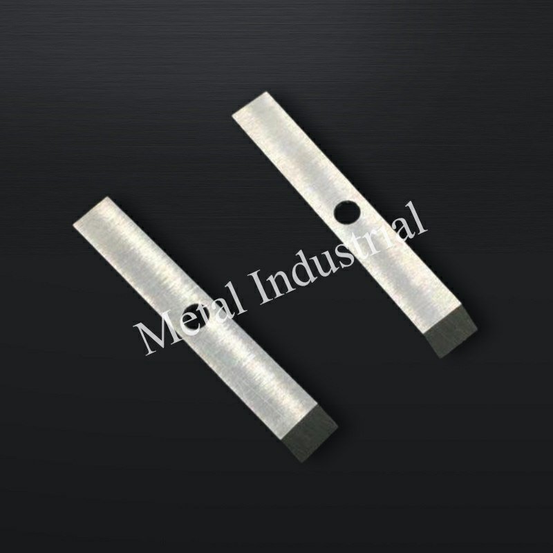
Un corte estable en la cara de la matriz es el resultado de un sistema: el grado de carburo y la preparación del borde determinan el comportamiento de desgaste/viruta; el diseño compuesto y la soldadura mantienen el inserto en su lugar; los controles de presión/alineación mantienen el contacto dentro de un rango estrecho; y el circuito de agua evita que las variables térmicas y de contaminación varíen.
Para los equipos de ingeniería de Maxtor Metal, la conclusión práctica es la misma que para los equipos de planta: definir la ventana de inserción (HRA 88-92 es un buen punto de partida), verificar el radio/acabado del borde, validar la rigidez de la soldadura y del soporte, y luego bloquear los controles del circuito de agua antes de ajustar la presión de la cuchilla.
For medical-grade or food-packaging polymer lines where water-loop chemistry control, ASTM A967 passivation, and contamination traceability are formal quality requirements, the knife specification and loop SOP framework is covered in our guide on 420 vs 440C stainless knife selection and water-loop control for medical polymer pelletizing.
Si está estandarizando la selección de cuchillas en diferentes sistemas de troquelado, Maxtor Metal también mantiene una guía dedicada sobre Cómo elegir las cuchillas de peletizadora de anillo de agua para líneas de PE/PP Esto puede ayudar a armonizar los criterios de selección en todos los sitios web.
Maxtor Metal Página de la cuchilla de la peletizadora de plástico Este documento recoge las convenciones de nomenclatura, las dimensiones y las tolerancias controladas por dibujo que se utilizan en todos los formatos de cuchillas; es el punto de referencia para armonizar las especificaciones entre plantas y proveedores.
- Conclusiones clave para materiales, diseño y operaciones.
- Próximos pasos: matriz de selección, SOP y registro de SPC
FAQs:
P: ¿Qué causa los finos en una peletizadora bajo agua?
R: Los finos generalmente aumentan cuando el filo se desgasta o presenta microdesportilladuras, cuando la presión de contacto es inestable o cuando el circuito de agua recircula contaminación abrasiva. Verifique conjuntamente el estado del filo, la tendencia de la presión y el rendimiento de la filtración.
P: ¿Qué dureza deben tener los insertos de carburo de tungsteno para la peletización en la cara de la matriz?
R: Muchas plantas buscan un rango de dureza HRA de alrededor de 88–92 para los insertos de WC-Co, y luego realizan ajustes dentro de ese intervalo según la abrasividad y la estabilidad del contacto. La dureza debe combinarse con controles de la microestructura, en lugar de considerarse como el único criterio de aceptación.
P: ¿Por qué me salen colas o hilos ("pelo de ángel") en las peletizadoras de anillo líquido?
R: Las colas suelen provenir de un cizallado inestable en la cara de la matriz: desalineación, fuerza de contacto insuficiente o con deriva, desgaste de la cara de la matriz o desequilibrio térmico en el arranque. Confirme el estado de la cara de la matriz y la estabilidad de la temperatura/flujo del agua antes de aumentar la presión.
P: ¿Pueden los insertos de carburo más duros dañar la cara de la matriz?
R: Sí, pueden si el control de contacto es deficiente o si los operadores compensan la inestabilidad aplicando una presión excesiva. El enfoque más seguro es una alineación estable + un ajuste de presión controlado, y luego elegir una dureza y preparación del filo que resistan el desgaste sin desportillarse.
P: ¿Qué temperatura del agua debo mantener para la peletización bajo agua?
R: Un rango estable común es de 40–60°C, pero la prioridad es mantener la temperatura constante y asegurar un flujo uniforme a través de la cara de la matriz. Las grandes variaciones pueden cambiar el comportamiento de solidificación y generar defectos en los pellets.
P: ¿Qué micraje de filtración es típico para el agua de proceso de una peletizadora bajo agua?
R: Muchas plantas comienzan en el rango de 100–200 µm para reducir los residuos recirculados y proteger los componentes. El límite "correcto" depende de la contaminación de la resina, la carga de residuos de desgaste y qué tan sensible sea la calidad del corte a la recirculación abrasiva.
P: ¿Cómo saber cuándo cambiar las cuchillas de la peletizadora antes de que baje la calidad?
R: Utilice indicadores clave: aumento de la tasa de finos, mayor dispersión en la longitud de los pellets e incremento de la corriente del motor a rendimiento constante. Muchos equipos cambian o reasfilan las cuchillas al alcanzar un umbral de KPI definido, en lugar de esperar a una falla visible.
Nancy Wu, Ingeniera Superior de Fabricación (PE — Ingeniería de Producción), Maxtor Metal. Nancy cuenta con 12 años de experiencia en la fabricación de cuchillas industriales y en el soporte de aplicaciones, con experiencia práctica en el mecanizado y el comportamiento de rectificado de materiales comunes para cuchillas (D2, M2, H13, aceros metalúrgicos en polvo y carburos cementados), características de recubrimiento y programación de rectificado CNC de alta precisión.
Certificaciones: Certificaciones SME–CMfgE, PMP, Six Sigma Black Belt, ASM International.
Cómo validamos las recomendaciones: Las ventanas de operación y las directrices para la resolución de problemas que se describen en este artículo se basan en los patrones de resolución de problemas de producción observados en los programas de cuchillas de peletizadoras y en los controles de control de calidad de fabricación. Los pasos de validación típicos incluyen la medición de la geometría del borde (radio/acabado del borde), la comprobación de la planitud y la excentricidad del bloque ensamblado, la verificación de la calidad de la soldadura (espacio/humectación/alineación) y la correlación de los KPI de calidad del pellet (distribución de finos/colas/longitud) con la corriente del motor y la estabilidad del circuito de agua. Confirme siempre los límites de su planta (estado de la cara de la matriz, rigidez/excentricidad del cubo, control del circuito de agua) antes de ampliar la ventana o aumentar la fuerza de contacto.

 English
  Spanish
  Italian
  French
  Portuguese
  Russian
  German
  Arabic
  Hindi
Hindi  Vietnamese
  Indonesian
  Japanese
  Korean