

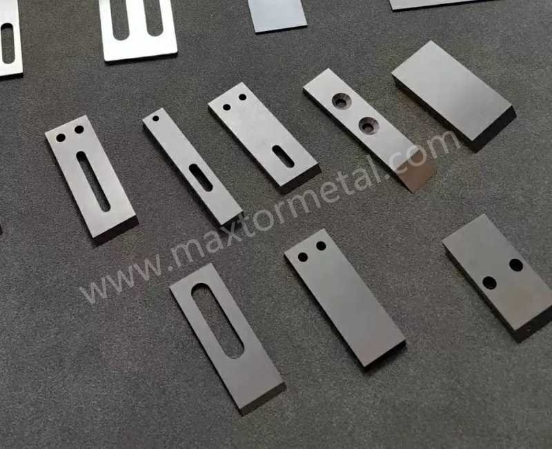
クイック回答: 水中ペレタイザーラインにおけるダイフェイス(ダイス金型面)での安定したカット面形成は、4つのインターロック変数は依存します:超硬の材質グレード(多くのWC-Co製造粒刃ではHRA 88〜92)、刃先幾何形状(単に「鋭利」なだけでなく、管理された刃先R)、接触圧管理(エンゲージ後にトリミング、過度な押し込み圧力追従の回避)、およびウォーターループの安定性(40〜60℃、ろ過・脱気済)。ダイフェイスの面粗度公差やカッターヘッドの動バランスを修正せずに超硬刃だけを交換することは、超硬アップグレードの効果が十分に発揮されない最も典型的な原因です。
ダイフェイス造粒における超硬インサート(造粒刃)とは、鋼製の台金(キャリアブロック)にろう付けされたWC-Co系超硬合金の焼結切削エレメントのことです。ポリマーの連続混練・造粒プロセスにおいて、1,000〜4,000 RPMで回転するダイス金型面(ダイフェイス)に対し、安定した刃先を維持できるように設計されています。
LDPEおよびPPのメガスケール生産ラインにおいて、稼働率が低下するのはナイフの摩耗そのものが原因ではありません。カットが不安定になること、つまり微粉(ファイン)の増加、テール(ひげ)の発生、電流値の変動、およびオペレーターが設定調整に追われるようになることが原因です。.
本ガイドは、ダイフェイス造粒システム(水中ペレタイザーおよびホットカットウォーターリングペレタイザー)向けに作成されています。インサートの材質グレード、刃先幾何形状、接触圧、そしてウォーターループ制御におけるわずかな狂いが、ラインを数週間連続稼働させられるか、それとも今夜稼働停止(ドロップ)に追い込まれるかの分岐点となります。
Maxtor Metalの製品ページ( プラスチックペレタイザーブレード 用)では、ダイフェイスシステムで使用されるナイフの形状、寸法、公差の全範囲を網羅しており、操業、メンテナンス、調達の間で用語を統一するための有用なリファレンスとなります。.
- 対象読者:水中ペレタイザーまたはウォーターリングペレタイザーを使用するLDPE/PPメガスケールプラント
- 目的:稼働率の最大化、ペレット品質の安定化、微粉(ファイン)およびテール(ひげ)の削減
- 本ガイドの構成:材質(HRA 88–92)、設計、制御、水循環ループ、KPI
WC-Co(タングステンカーバイド・コバルト)材質グレードと硬度
インサート型ナイフに使用される超硬合金は、一般的にコバルトバインダーを含むタングステンカーバイド(WC–Co)です。実際の現場における材種の選択は、硬度(耐摩耗性)と靭性(耐チッピング性)のバランスであり、最適なポイントは樹脂の研磨性、フィラー含有量、および接触制御の安定性によって決まります。.
超硬合金の硬度は、一般的にロックウェルAスケール(HRA)で規定され、試験方法とスケールの定義は標準化されています。特に超硬合金においては、, ASTM B294 — 超硬合金の硬さ試験 がロックウェルHRA試験手順(ダイヤモンド圧子、基準荷重 10 kgf、試験荷重 60 kgf)を定義しており、より広範なロックウェル試験方法については以下を参照しています。 ASTM E18 — 金属材料のロックウェル硬さ試験方法. 。また、多くの試験機関では、規格間の整合性を保つためにロックウェル試験の実務を以下に合わせています。 ISO 6508(ロックウェル硬さ) )に準拠させ、規格間の整合性を確保しています。.
製造管理においては、硬度の許容幅(ウィンドウ)と期待される微細組織(粒径および気孔率)をセットで規定する必要があります。なぜなら、2つのインサートが同じHRAを示したとしても、刃先での挙動が異なる場合があるためです。.
チーム間で用語を統一する場合、Maxtor Metalのガイドである ペレタイザーブレードの圧力調整とダイ保護 は、カット不良を制御可能な設定(圧力、ダイ保護、運転ウィンドウ)に関連付けているため、非常に役立つリファレンスとなります。.
タングステンカーバイド(超硬)インサートの選定範囲
多くのプラントがダイフェイスカット用インサートの目標とする実用的な範囲は、 HRA 88〜92. です。この範囲が意図的に広く設定されている理由は以下の通りです。
- 下限値付近(≈88–89 HRA):バインダー量が多く靭性が高いため、接触制御が不完全な場合、スタートアップ時の接触(こすれ)が発生する場合、またはダイフェイスが完全に平坦でない場合に安全な選択肢となります。.
- 上限値付近(≈91–92 HRA):耐摩耗性が高いため、研磨性の高いコンパウンドを運転する場合や、圧力スパイクを起こさずにニアゼロギャップ(極小隙間)を維持する場合に有用です。.
「証明書に記載されたHRA」以外に検証すべき項目:
- 焼結超硬の粒径および気孔率評価 (粗い粒径や高い気孔率は、断続的な接触下での刃先チッピングリスクを高めるため)。.
- ロット間のばらつき(一貫性) (サプライヤーが異なると、同じ材種表記であっても微細組織が同じとは限りません)。.
仕様書を作成する必要がある場合:公認されている超硬合金の分類用語を参照し(多くのサプライヤーはISO適用分類に対応しています。以下を参照: ISO 513 超硬合金の適用分類)に準拠し、自社の破損モードにおいて重要となる受入検査基準を確定させてください。.
刃先R(エッジ半径)と仕上げ
水中カットにおいて、刃先はいつまでもカミソリのように鋭利なわけではありません。水冷、熱サイクル、および時折発生する接触(こすれ)の下で安定性を維持しなければならない「実用刃先」です。通常、次の2つの刃先パラメータが、予想以上に早くペレット品質に影響を与えます。
- 刃先R(エッジ半径) (ミクロン単位の管理が重要):鋭すぎる刃先はマイクロチッピングのリスクを高め、鈍すぎる刃先は溶融樹脂を「押し出す」ことになり、テールやスメア(にじみ)を増加させます。このトレードオフは、一般的な切削力学の文献とも一致しています。適切に処理・丸められた刃先はチッピングに対する堅牢性を向上させますが、刃先Rが大きくなると、 プラウイング(むしり取り) 効果によってスラスト力(押し付け力)が増大する可能性もあります(以下を参照: Wyen & Wegener (2010), CIRP Annals — 刃先丸み半径が表面インテグリティに及ぼす影響).
- 刃先の仕上げ:研削痕やバリはクラック(ひび割れ)の起点となり、ダイランド部での均一なせん断を妨げます。.
実用的なアプローチとしては、刃先Rを管理されたプロセス変数として扱うことです。
- 単に「鋭利」とするのではなく、目標とする刃先Rの範囲を定義し、測定(投影機や顕微鏡を使用)します。“
- 再研磨の判断は、目視検査だけに頼るのではなく、ペレットの評価指標(微粉、テール)と連動させます。.
フィラー入りPP/PE用コーティング
フィラー入りPP/PEや研磨性の高いマスターバッチにおいて、コーティングは付着を低減し、刃先の摩耗を遅らせるのに役立ちます。ただし、これはベースとなる刃先が安定している場合にのみ効果を発揮します。.
操業上重要なポイント:
- Coating purpose: anti-adhesion vs abrasion resistance vs corrosion resistance.
- Failure mode: if you see coating flake/chip at the edge early, you likely have an edge-prep or contact-pressure issue before you have a “bad coating” problem.
- Compatibility with regrind: decide whether coated inserts are disposable or re-coatable; build that into the cost model.
In short — materials and grade selection: HRA 88–92 is the starting spec, but grain size, porosity, and lot-to-lot consistency are what decide whether that number translates into stable edge life at the die face.
For lines where the wear mechanism is driven by glass-fiber loading rather than bulk abrasion — and where the blade material is PM stainless rather than cemented carbide — the parallel grade selection logic between M390 and CPM S90V is covered in our guide on powder metallurgy pelletizer blade selection under high glass-fiber wear.
複合超硬ブロック(台金結合)の意匠設計
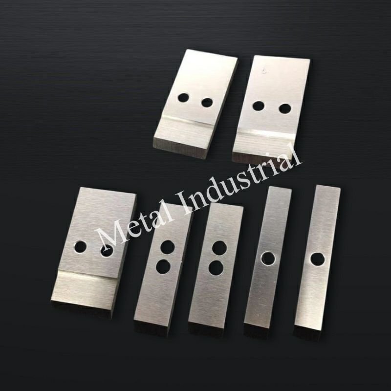
Insert knives rarely fail “because carbide is carbide.” They fail because the composite assembly can’t keep the edge tracking the die face consistently over time.
Brazing and joint integrity
The braze joint is a structural element. If it creeps, cracks, or distorts under thermal cycling, your insert can stay hard and still cut badly.
Maxtor Metal’s QA process for knife block assemblies includes braze gap verification, wetting inspection, and flatness/runout measurement to drawing tolerances — with sample cross-sections as part of the pre-release checklist.
What to check in your own acceptance plan:
- Braze alloy selection suited to operating temperature and corrosion environment.
- Braze gap control and evidence of full wetting (avoid voids at the highest-stress edge zone).
- Post-braze distortion: measure flatness and runout on the assembled block, not just the insert alone.
Carrier stiffness and tracking
Carrier stiffness is what converts a setpoint into a real, repeatable contact condition.
If the carrier flexes, your “pressure” becomes a mix of actual edge load plus vibration — and the vibration is what makes fines and intermittent tails.
Checks that usually pay back:
- Verify hub-to-carrier seating and fastener torque control (repeatability beats “tight enough”).
- 測定 dynamic runout at operating speed; static runout alone misses a lot.
- Ensure the carrier design maintains stiffness across temperature (thermal growth can change tracking).
Balance and sweep over die holes
A cutter hub can be “balanced” and still cut unevenly if the sweep doesn’t cover the die-hole pattern correctly.
What to validate during commissioning and after major maintenance:
- Sweep coverage: confirm the blade path overlaps the full active die-hole ring, including any segments that are intentionally blocked or blanked.
- Balance at real speed: imbalance raises bearing load, injects vibration, and forces operators to compensate with pressure — which accelerates both knife and die wear.
For the full balance grade calculation, runout acceptance criteria, and QA dossier structure that apply to knife block assemblies at 1,000–4,000 RPM, see our 水リング式ペレタイザー用ナイフブロックの適格性評価フレームワーク.
In short: insert hardness is only as good as the assembly that keeps it tracking the die face — braze integrity, carrier stiffness, and dynamic balance are what the carbide relies on.
現場向けクイックトラブルシューティングマップ
Use this as a fast “symptom → first checks → adjustment” path before you start changing knife pressure.
- Tails/stringers jump suddenly → verify die-face condition (grooves/high spots), cutter-head runout、 そして water temperature stability → then re-check contact pattern and trim pressure.
- Fines climb gradually → verify filtration performance, recirculated debris, and edge finish/wear → then review edge radius targets and regrind thresholds.
- Motor amps drift up at constant throughput → correlate amps with pellet appearance: rising amps + worse pellets usually means rubbing → confirm alignment and reduce contact after stabilization (engage → trim).
- Startup is unstable (freeze-off / tails / vibration) → prioritize thermal balance (water loop temperature/flow distribution, degassing) and clean seating surfaces → only then adjust speed/pressure.
In short: tails, fines, and amps each point to a different root cause — match the symptom to the right check before touching pressure.
カッター刃の接触と圧力制御
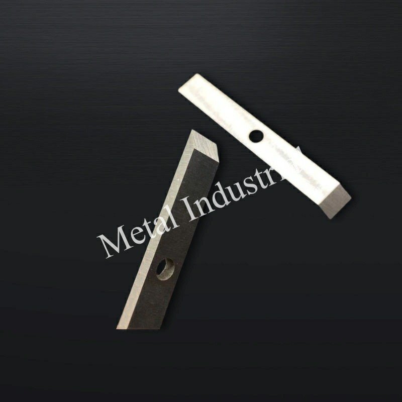
Contact control is where quality and uptime converge. A stable cut usually comes from a narrow operating window: enough force to shear cleanly, not enough to plow the die face.
Pressure and near-zero gap
Many plants aim for a near-zero gap condition (or very small clearance) with controlled contact pressure, because that’s the easiest way to keep pellet length stable.
To keep it stable:
- Engage → trim strategy: engage with higher force to seat and stabilize, then trim down once pellets and amps stabilize.
- Watch motor current trend and pellet appearance together; if current rises while pellet quality degrades, you’re often rubbing rather than cutting.
重要なポイント: If operators routinely “solve” tails by increasing knife pressure, you’ll often buy short-term quality at the cost of rapid die-face grooving.
Alignment and run-in
Alignment problems look like “mysterious” pellet defects because they show up as intermittent tails, twins, or fines spikes.
Run-in should be treated as controlled stabilization, not a trial-by-fire:
- Verify seating surfaces are clean and repeatably torqued.
- Use a short run-in at controlled conditions, then re-check runout and contact pattern.
- If the die face has any feelable groove or high spot, correct it before you chase knife settings. (Die condition drives knife behavior as much as the insert does.)
Speed and cut frequency
Cut frequency is the bridge between polymer flow and pellet geometry. When speed changes, you change:
- Pellet length distribution
- Heat generation at the edge
- The “time under load” per pass
A practical control approach:
- Stabilize throughput, then adjust cut speed to hit pellet spec.
- If you’re increasing speed to “fix” tails, verify the upstream root cause (viscosity, die temperature, water flow) first.
For tacky polymer lines — particularly TPU and EVA — where contact pressure mismanagement is the primary trigger for knife gumming and adhesion buildup, the mechanism-level diagnostic and DLC vs PTFE coating selection logic is covered in our guide on stopping knife gumming in TPU underwater pelletizing.
In short: a stable cut comes from engaging with enough force to seat cleanly, then trimming down — not from chasing defects with increasing pressure.
水循環ループ(ウォーターループ)工学
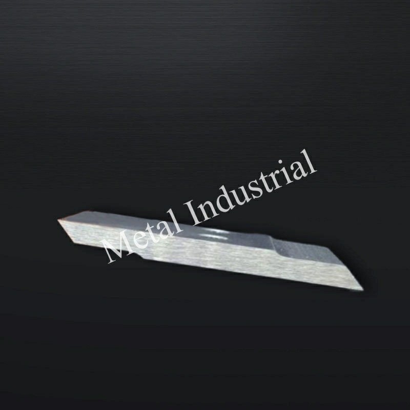
The water loop is not just cooling — it’s a stability system. Water temperature, flow, cleanliness, and entrained gas all show up at the cut.
Temperature and flow
A workable control band for many operations is 40–60°C process water temperature, because it tends to reduce thermal shock while keeping pellets from smearing.
What to manage in practice:
- Temperature stability beats absolute temperature: a drifting loop changes polymer solidification behavior and can look like “random” tails.
- Flow distribution at the die face: dead zones create local freeze-off risk or local over-heating.
If you see startup instability, it’s often a thermal balance problem. Research on die-face pelletizing and freeze-off highlights how heat transfer conditions can drive irregular cutting and tails (see International Journal of Heat and Mass Transfer (2022), article overview). Practical troubleshooting guidance from Plastics Technology also emphasizes that die-hole freeze-off is commonly driven by start-up sequencing, inadequate die heating/insulation, and process fluctuations — see Plastics Technology: Stop die-hole freeze off.
Filtration and degassing
Filtration and degassing are “hidden variables” that decide whether your knife and die face operate in clean water or in a slurry.
- Filtration (coarse protection + side-stream cleanup): Many plants start with a coarse strainer / screen to protect pumps and seals, then rely on side-stream filtration to steadily remove suspended solids without disrupting main flow. For closed-loop water systems, ChemAqua’s guidance describes using progressively finer filters during cleanup (for example, stepping from 50 µm to 20 µm and then to 10 or 5 µm once filters can stay online without blinding) — see ChemAqua: Filtration options for closed-loop systems.
- Degassing: removes entrained air that can cause cavitation, unstable flow, and inconsistent cooling at the die face.
Operational signs you’re under-filtered or under-degassed:
- Gradual fines increase with no obvious geometry change
- Unstable flow indications at constant pump speed
- Rapid edge polish/loss of finish even with stable pressure
Thermal stability and drying
A stable cut is only half the story; you also need stable downstream handling.
- Keep loop control tight enough that pellet surface moisture is predictable.
- If drying performance swings, don’t only blame dryers — verify water temperature stability and degassing first.
In short: water temperature stability, filtration, and degassing are process variables, not maintenance tasks — drifting loop conditions show up as pellet defects before they show up on gauges.
重要業績評価指標(KPI)と投資対効果(ROI)
A knife program becomes scalable when you translate “feels sharp” into KPIs that predict failure 前に quality drops.
What changes first when you change inserts or settings?
The table below is a practical “directional map” teams use to predict what will move when you change grade, edge prep, or contact strategy.
Boundary conditions: これらは typical trends for die-face cutting on PE/PP lines. Your actual results depend on resin/filler abrasiveness, die-face condition, hub stiffness/runout, and water-loop stability. Validate on your line and document the operating window.
| Change you make | Typical effect on fines | Typical effect on tails/stringers | What to watch operationally | Risk if pushed too far |
|---|---|---|---|---|
| Higher hardness / more wear-resistant insert (within a stable grade family) | Often ↓ over time (slower wear) | Often ↓ if edge stays stable | Track edge micro-chipping and vibration | Can ↑ die-face grooving if contact control is poor |
| Sharper edge / smaller edge radius | Can ↓ initially | Can ↓ initially (cleaner shear) | Monitor sudden fines spikes (micro-chipping) | Higher chipping risk during rub/startup events |
| Larger edge radius / heavier edge prep | Can ↑ if edge starts “pushing” melt | Can ↑ (more smear/tails) | Look for pellet smear and current increase | Over-prep behaves like a worn edge |
| Pressure-heavy strategy (solving defects by loading force) | Mixed; can hide wear briefly | Can ↓ short-term | Watch amps trend and die-face wear | Accelerates die wear; can shorten insert life |
| Engage → trim strategy (seat, stabilize, then reduce) | Often ↓ (less rubbing) | Often ↓ (more stable shear) | Use pellet metrics + current together | Needs repeatable torque/runout control |
Anonymous engineering case (abrasive CaCO₃-filled PP)
To make the “insert vs. process control” discussion concrete, here’s an anonymized field comparison from a continuous underwater pelletizing line processing an abrasive compound.
注記: This example is constructed from typical field patterns observed across pelletizer knife programs; it is not a single customer’s raw inspection record. Operating results will vary based on resin, filler content, die-face condition, and process control maturity.
Material and operating window (held constant): PP homopolymer with 25 wt% CaCO₃ (+0.5–1.0% processing aid), 7.5–8.5 t/h, MFI 8–12 g/10 min; cutter speed 2,700–3,100 rpm; process water 55–65°C; ~850 die holes; 24/7 operation.
Test design: The plant replaced a conventional hardened tool-steel knife with an inserted tungsten carbide cutting edge while holding knife geometry, knife pressure setpoint, cutter speed, die plate, operators, and recipe constant. Replacement was triggered when fines exceeded 1 wt% または tails exceeded 0.5% (not a fixed time interval).
Observed results (16 weeks, 12 campaigns, ~3,250 t processed, 96 pellet samples, 14 blade sets):
- 罰金: 1.35 wt% → 0.46 wt% (−66%)
- Tails/stringers: 0.82% → 0.18% (−78%)
- Average blade life: 185 h → 515 h (2.8×)
- Throughput before edge degradation: ~1,480 t → ~4,100 t (2.8×)
- Unplanned shutdowns: 5 events/quarter → 1 event/quarter (−80%)
- Blade change interval: every 8 days → every 22 days (+175%)
First attempt that failed (why “carbide alone” wasn’t enough): The initial trial upgraded blade material only. With no change to die-face condition or cutter-head balance, fines stayed around ~1.1 wt% and several carbide edges chipped after ~120 hours. Inspection found shallow circumferential die-face grooves. After resurfacing the die, dynamically balancing the cutter head、 そして reducing knife contact force by ~10–15%, the inserts delivered stable long-term performance.
Operational learning: Teams that trimmed pressure after the first hour (as thermal growth stabilized) saw less die wear and less shift-to-shift variation than teams that increased pressure whenever tails appeared. After operator training to rely on pellet-quality measurements instead of “pressure chasing,” blade-life variation dropped from ~±18% to ~±6% across shifts.
Pellet quality metrics
Track metrics that are fast to measure and strongly tied to customer complaints:
- Fines (% by weight) at a defined sampling method and interval
- Tails/angel hair rate (count-based or weight-based)
- Pellet length distribution (mean and standard deviation)
Tie each metric to the controllable knobs:
- If fines rise while tails stay flat, suspect edge wear/finish.
- If tails rise suddenly, suspect contact pressure, alignment, die face condition, or thermal imbalance.
Knife life and die wear
Treat knife life and die wear as a coupled system:
- A pressure-heavy strategy can extend pellet quality temporarily while accelerating die-face wear.
- A too-hard, too-sharp edge can look great for hours and then chip, creating a sudden fines jump.
Track:
- Knife life hours/tons per insert set
- Die recondition interval and the trigger (groove depth, hole edge rounding)
- Regrind count and thickness loss (if relevant)
Availability, rate, and cost
ROI is usually won by avoiding unplanned stops and stabilizing quality, not by shaving a small amount off unit knife cost.
A simple way to model it:
- Availability gain: reduced stop frequency × average stop duration
- Rate protection: fewer “quality slowdowns” to stay in spec
- Quality yield: reduced off-spec and customer claims
If you already track OEE, add a small set of knife-specific tags so you can separate “knife-driven” events from upstream process events.
In short: the ROI case for tungsten carbide inserts is built on avoided stops and stable quality yield, not on unit-cost comparison — track availability and rate loss, not just blade price.
結論
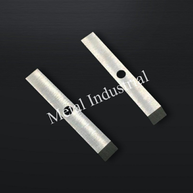
A stable die-face cut is a system outcome: carbide grade and edge prep set the wear/chip behavior; composite design and brazing keep the insert where it should be; pressure/alignment controls keep contact inside a narrow window; and the water loop keeps thermal and contamination variables from drifting.
For Maxtor Metal’s own engineering teams, the practical takeaway is the same as for plant teams: define the insert window (HRA 88–92 is a useful starting point), verify edge radius/finish, validate the braze and carrier stiffness, then lock the water-loop controls before you chase knife pressure.
For medical-grade or food-packaging polymer lines where water-loop chemistry control, ASTM A967 passivation, and contamination traceability are formal quality requirements, the knife specification and loop SOP framework is covered in our guide on 420 vs 440C stainless knife selection and water-loop control for medical polymer pelletizing.
If you’re standardizing blade selection across different die-face systems, Maxtor Metal also maintains a dedicated guide on how to choose water ring pelletizer blades for PE/PP lines that can help align selection criteria across sites.
Maxtor Metal’s プラスチックペレット製造機の刃のページ documents the naming conventions, dimensions, and drawing-controlled tolerances used across knife formats — the reference point for aligning specs between plants and suppliers.
- Key takeaways for materials, design, and operations
- Next steps: selection matrix, SOPs, and SPC logging
FAQs:
Q: 水中ペレタイザーで微粉(ファイン)が発生する原因は何ですか?
A: 微粉は通常、刃先(カッティングエッジ)の摩耗や微小欠け(チッピング)、接触圧の不安定化、あるいはウォーターループ(水循環)内で研磨性コンタミ(摩耗性異物)が再循環することによって増加します。刃先の状態、圧力トレンド、およびフィルターのろ過性能を総合的に点検してください。
Q: ダイフェイス造粒用超硬インサート(造粒刃)の最適な硬度はどれくらいですか?
A: 多くの現場では、WC-Co製インサートの硬度指標としてHRA 88〜92のレンジをターゲットとし、樹脂の摩耗性(フィラー含有量等)や接触安定性に基づいてその範囲内で微調整を行います。硬度は単一の受入検査基準として扱うべきではなく、金相組織(マイクロストラクチャ)の制御管理とセットで評価する必要があります。
Q: ホットカットウォーターリングペレタイザーで、ペレットにテール(ひげ)やエンゼルヘア(糸引き)が発生するのはなぜですか?
A: テールや糸引きは、多くの場合、ダイフェイス部での不安定なせん断(カッティング不整合)に起因します。具体的な原因としては、軸芯のズレ(アライメント不良)、接触圧の不足や変動、ダイフェイスの摩耗、起動時の熱不均衡(サーマルバランスの崩れ)が挙げられます。押し込み圧力を強める前に、必ずダイフェイスの表面状態と、循環水の温度・流量の安定性を確認してください。
Q: 高硬度の超硬インサート(造粒刃)はダイフェイス(金型面)を傷つける原因になりますか?
A: 接触制御(アプローチ管理)が不適切であったり、カットの不安定さを補うためにオペレーターが過度な押し込み圧力をかけたりすると、傷つく原因になります。安全なアプローチとしては、「正確なアライメント調整 + 制御された圧力微調整」を徹底し、その上で欠け(チッピング)を起こさずに摩耗に耐える最適な硬度と刃先処理(エッジプレパレーション)を選択することです。
Q: 水中ペレタイザー(アンダーウォーターペレタイザー)を稼働させる際、循環水の適正温度はどれくらいですか?
A: 一般的な安定領域は40〜60℃ですが、最も重要なのは「温度を一定に保つこと」と「ダイフェイス(金型面)全体に均一な水流を確保すること」です。水温が大きく変動すると、樹脂の凝固挙動(固まり方)が変化し、ペレットの成形不良や欠陥を引き起こす直接的な原因となります。
Q: 水中ペレタイザーのプロセス水(循環水)における一般的なろ過精度(フィルターサイズ)はどれくらいですか?
A: 多くの工場では、循環するコンタミを低減しシステム構成部品を保護するために、まず100〜200 µmの範囲から導入します。「最適な」カットオフ(目開き)は、樹脂中の異物量、摩耗粉の堆積負荷、そしてカット品質が研磨性物質の再循環に対してどの程度敏感であるかによって決まります。
Q: Bagaimana cara mengetahui kapan harus mengganti pisau pelletizer sebelum kualitas produk menurun?
A: 先行指標として、「微粉(ファイン)発生率の上昇」「ペレット長のバラつき(粒長分布の拡大)」「一定処理量におけるモーター電流値の上昇」を監視してください。多くの現場では、目視できる製品不良が出るまで待つのではなく、設定したKPIのしきい値(管理基準値)に基づいてブレードの交換や再研磨を実施しています。
Nancy Wu, Senior Manufacturing Engineer (PE — Production Engineering), Maxtor Metal. Nancy has 12 years of experience in industrial blade manufacturing and application support, with hands-on expertise in the machining and grinding behavior of common blade materials (D2, M2, H13, powder metallurgy steels, and cemented carbides), coating characteristics, and high-precision CNC grinding programming.
認定資格: SME–CMfgE, PMP, Six Sigma Black Belt, ASM International certifications.
推奨事項の検証方法: The operating windows and troubleshooting guidance in this article are based on production troubleshooting patterns observed across pelletizer knife programs and on manufacturing QA controls. Typical validation steps include measuring edge geometry (edge radius/finish), checking assembled block flatness and runout, verifying braze quality (gap/wetting/alignment), and correlating pellet-quality KPIs (fines/tails/length distribution) with motor current and water-loop stability. Always confirm your site’s limits (die-face condition, hub stiffness/runout, water-loop control) before widening the window or increasing contact force.

 English
  Spanish
  Italian
  French
  Portuguese
  Russian
  German
  Arabic
  Hindi
Hindi  Vietnamese
  Indonesian
  Japanese
  Korean