

النقاط الرئيسية:
- الآلية الأساسيةلا ينجم تولد غبار التقطيع عن حافة القطع الثلمة فحسب؛ بل ينجم بشكل أساسي عن احتكاك النتوءات الدقيقة على جانب الشفرة أثناء احتكاكها بحافة الشريط المقطوعة حديثًا.
- عتبة القياس المترولوجيإن تقليل الخشونة السطحية لجانب الشفرة من المستويات التجارية القياسية (Ra 0.4–0.8 µm) إلى التشطيب الفائق بالصقل المرآتي (Ra < 0.1 µm) يقلل من الاحتكاك الدقيق بنسبة تصل إلى 60٪، مما يوقف تساقط الجسيمات على خطوط الإنتاج فائقة السرعة.
- الاختيار الميتالورجييعاني صلب D2 أو SKD11 التقليدي من انقلاع الكربيد أثناء التشطيب الفائق. يتطلب تحقيق تشطيب Ra < 0.1 µm والحفاظ عليه تحت شد الشريط المستمر استخدام صلب أدوات مسحوق المعادن (PM-M4) أو كربيد التنجستن فرعي الميكرون.
- الدقة النظاميةSpiegelpolierte Messer müssen mit strengen mechanischen Setup-Toleranzen kombiniert werden, einschließlich eines Axiallaufs ≤ 0,002 mm, korrekter Anstellwinkel und einer kalibrierten Überdeckungstiefe, um sekundäre Reibung zu verhindern.
تشكل هذه المبادئ الأربعة الإطار الهندسي الذي يطبقه فريق التطبيقات في Maxtor Metal عند اعتماد الشفرات الدائرية لبرامج التحويل الخالية من الغبار في خطوط التغليف المرن، والأقمشة غير المنسوجة، والورق الخاص.
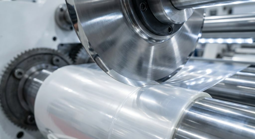
في عمليات التحويل عالية السرعة للتغليف المرن، والمنسوجات التقنية، والأقمشة غير المنسوجة، والورق الخاص، يعد التلوث بالجسيمات سببًا رئيسيًا للتوقف غير المخطط له لخطوط الإنتاج. وما يشخصه مشغلو المصانع غالبًا على أنه "ضعف شد الشريط" أو "عيوب في رول الخام" يعود في كثير من الأحيان إلى سبب جذري واحد: تولد غبار التقطيع الذي يحدث بالضبط عند نقطة القص الهيدروليكي/المقصي.
عندما تتراكم رقائق البوليمر المجهرية أو شظايا الألياف أو جزيئات الطلاء غير العضوية على رولات الشريط المقطوع، تفشل العمليات اللاحقة. حيث تطلق أنظمة الفحص البصري إنذارات عيوب كاذبة، وتظهر في أحبار الطباعة ثقوب دقيقة (pinholes) بسبب الفراغات الناجمة عن الغبار، وتلتقط الرولات المشحونة بالكهرباء الساكنة الهواء، مما يؤدي إلى حدوث التليسكوب (الانزلاق المحوري) أثناء اللف.
في حين تتركز الممارسات التقليدية للصيانة بشكل شبه حصري على حدة الشفرة (نصف قطر حافة القطع)، توضح أبحاث علم الاحتكاك (الترايبولوجي) والقياسات الميدانية في المصانع أن نصف قطر الحافة ليس سوى نصف المعادلة. فالسبب الرئيسي لتساقط الغبار الدقيق هو بروفايل الخشونة السطحية لجانب الشفرة.
يفحص هذا التقرير الفني ميكانيكا منطقة القطع أثناء التقطيع الدائري بالقص، ويقيس تأثير مقاييس الخشونة السطحية (Ra, Rz, Rmax)، ويقيم البنية المجهرية لصلب الأدوات، ويحدد المعايير التشغيلية اللازمة لتحقيق أداء تقطيع خالٍ تمامًا من الغبار.
الميكانيكا الدقيقة لظاهرة غبار التقطيع: كيف تؤدي خشونة الجانب إلى تآكل الشريط
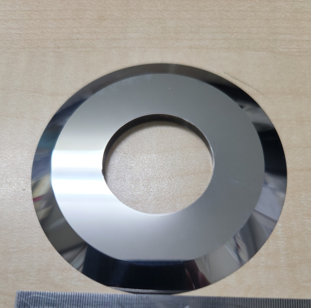
للقضاء على التلوث بالجسيمات، يجب على مهندسي عمليات التحويل تحليل تسلسل عملية الشق بالمقص ذي المرحلتين. فالشق بالمقص ليس مجرد عملية قطع بسيطة بالشفرة؛ بل هو كسر ميكانيكي محكوم يحدث بين سكين دائري مقعر علوي وطوق شق سفلي.
المرحلة 1: الانضغاط المرن-اللدن ← يتم ضغط المادة بين حواف الشفرة العلوية والسفلية.
احتكاك النتوءات المجهرية مقابل كسر القص النظيف
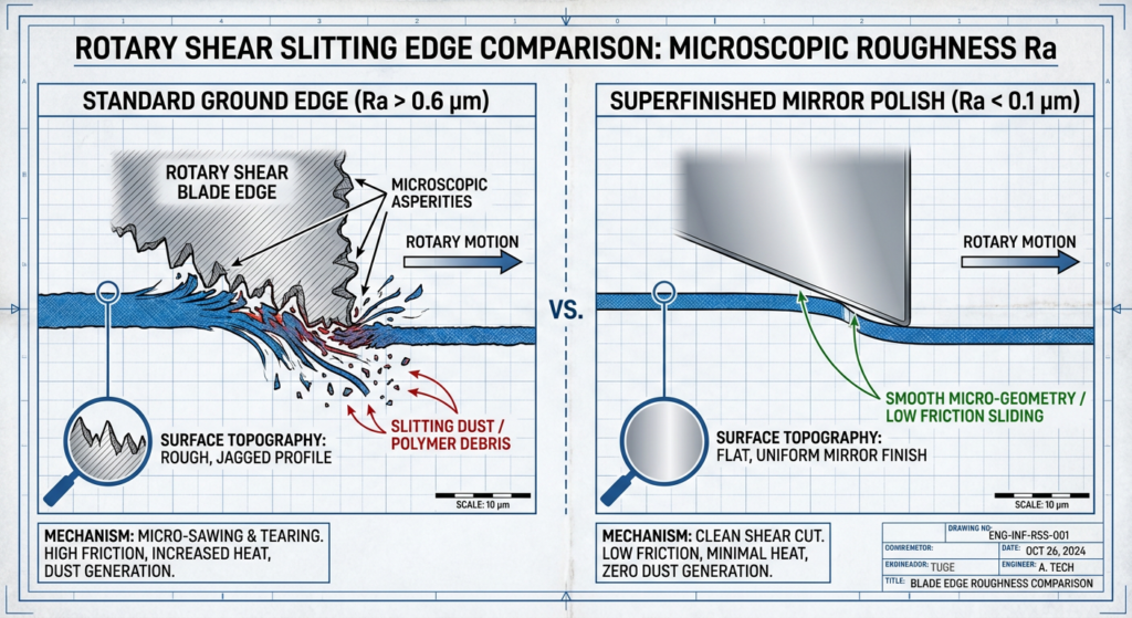
خلال المرحلة 3، تتحرك حافة الشريط المتكونة حديثاً على طول السطح الجانبي للسكين الدائري العلوي. وعندما يتم تجليخ الشفرة باستخدام أحجار تجليخ إنتاجية قياسية، يترك حجر التجليخ حزوزاً اتجاهية تسمى النتوءات المجهرية.
تحت تكبير بصري بمقدار 200x، يشبه السطح الجانبي للشفرة المجلخة بشكل قياسي منشاراً مجهرياً. ومع تحرك حافة الشريط متجاوزة هذه القمم بسرعات تتجاوز 300 متر في الدقيقة، تشتبك النتوءات بسلاسل البوليمر الفردية أو الألياف السليلوزية. وبدلاً من الانفصال النظيف، تتعرض المادة لتمزق مجهري موضعي، وتآكل، وتشويه بالقص. وتنفصل المادة الممزقة على شكل جسيمات دقيقة محمولة جواً أو حطام ملتصق بالكهرباء الساكنة. ويتوافق هذا مع الوثائق الهندسية الصادرة عن كبار موردي سكاكين الشق، والتي تشير إلى أن أسطح الشفرات الخشنة تتسبب في تنسيل الحواف المشقوقة أثناء مرور الشريط عبر السطح الجانبي، وأن جودة إعادة التجليخ يمكن أن تزيد من الغبار حتى عندما تبدو اللمسات النهائية المقاسة متشابهة.[2]
حلقة التغذية الراجعة للتآكل الاحتكاكي ثلاثي الأجسام
بمجرد انفصال جزيئات الغبار الأولية، فإنها تحفز دورة تدهور متسارعة:
- انحشار الجسيمات: يستقر الحطام الدقيق في فجوة الخلوص المجهرية بين شطبة الشفرة العلوية وحلقة السكين السفلية (الأنثى). كما تحدد هندسة الشطبة عند طرف السكين العلوي مقدار مساحة التلامس المعرضة لحلقة التآكل الاحتكاكي ثلاثية الأجسام هذه. وتعمل الشطبة المجهرية المركبة على تقوية الطرف ضد التثلم الناتج عن الجسيمات مع تقليل مساحة السطح الجانبي المعرضة — للحصول على إطار عمل لاختيار الشطبة القائم على الصلابة، انظر شطفات مفردة ومزدوجة ومركبة لسكاكين القطع الدائرية.
- التآكل الاحتكاكي ثلاثي الأجسام: تعمل الجسيمات الصلبة المحشورة (مثل حشوات كربونات الكالسيوم في الأفلام البلاستيكية أو أصباغ ثاني أكسيد التيتانيوم في الأقمشة غير المنسوجة) كمركب تجليخ وتنعيم كاشط.
- تآكل السطح الجانبي وانثلام الشفرة: يتسبب الحطام في خدش السطح الجانبي للشفرة، مما يزيد من خشونة السطح مع جعل حافة القطع الأساسية مستديرة.
- طفرة أسية في تولد الغبار: مع زيادة خشونة سطح الشفرة وانثلامها، يزداد عمق تمزق المادة، مما يؤدي إلى توليد كميات أكبر من الغبار.
حساسية ركيزة المادة
تظهر ركائز التحويل المختلفة أنماط فشل متميزة عند تعرضها لأسطح الشفرات الخشنة:
- أفلام BOPP و PET و PE: يولد الاحتكاك العالي طاقة حرارية موضعية عند حدود القطع. ويتسبب التسخين الناتج عن الاحتكاك في حدوث انصهار مجهري يليه كسر حراري هش، مما ينتج مسحوق بوليمر أبيض ناعم.
- الأقمشة غير المنسوجة والمنسوجات الاصطناعية: تلتقط النتوءات المجهرية الشعيرات الفردية، وتسحبها خارج المصفوفة المترابطة (تنسيل الألياف) بدلاً من قصها.
- الأوراق المطلية والورق المقوى: تتسبب الأسطح الجانبية الخشنة في تشقق الطبقة العلوية غير العضوية (الطين/اللاتكس)، مما يؤدي إلى إطلاق غبار معدني يؤدي إلى تآكل حواف صلب الأدوات بسرعة.
تحليل قياسات السطح (Metrology): لماذا يعد Ra < 0.1 µm هو الحد الأدنى للتقطيع الخالي من الغبار
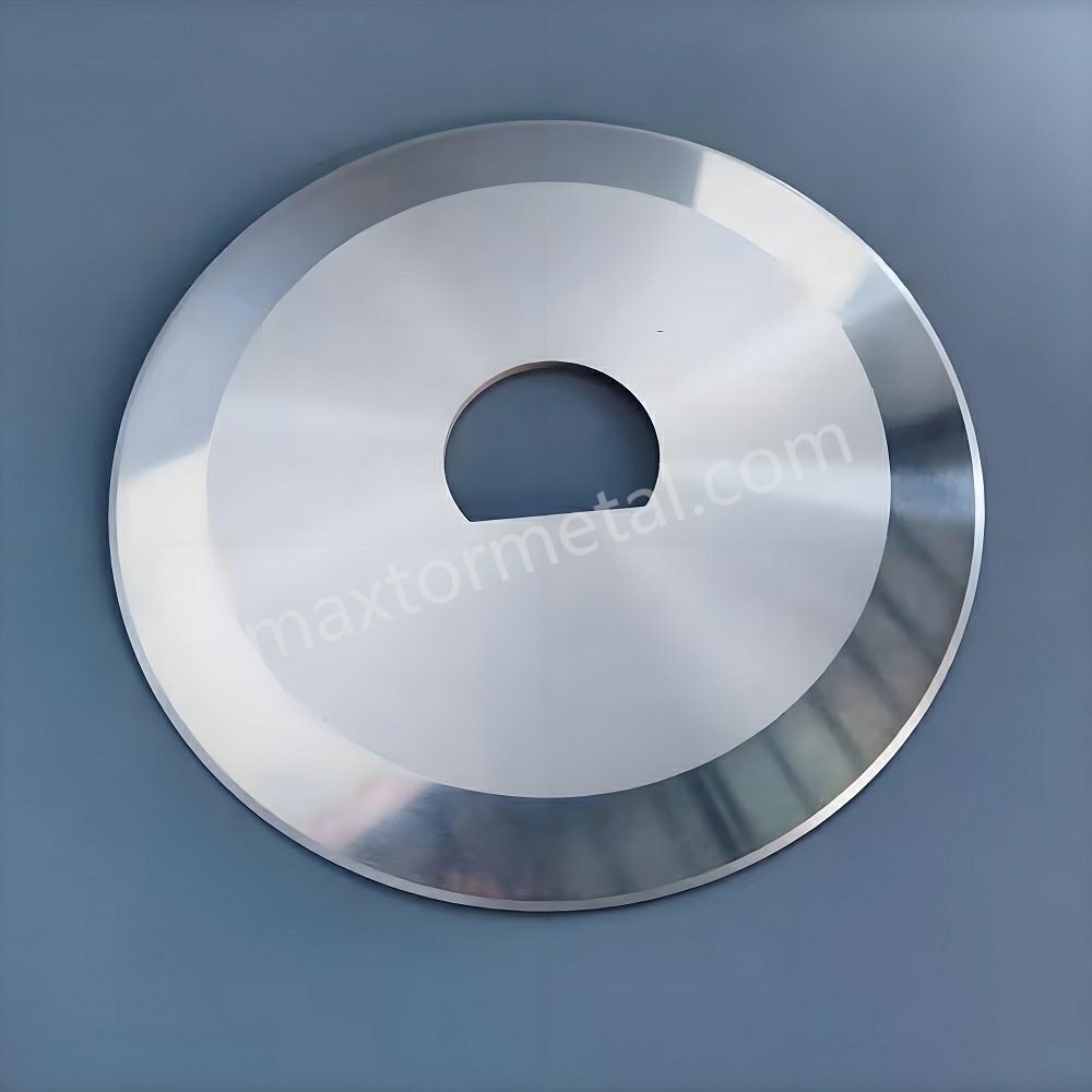
يتطلب تحديد جودة تشطيب السطح كمياً تجاوز المصطلحات الذاتية مثل “مصقول” أو “تشطيب لامع”. يجب على مديري المصانع تحديد معايير قياس السطح (المترولوجيا) باستخدام اختبار مقياس الملف الجانبي بموجب سلسلة مواصفات ISO 4287، التي تحدد معايير الملف الجانبي Ra و Rz و Rmax، ومواصفة ISO 4288 التي تحكم كيفية مقارنة القيم المقاسة بحدود التفاوت المسموح بها.[1]
- Ra (متوسط الخط المركزي): المتوسط الحسابي لانحرافات ارتفاع الملف الجانبي عن الخط المتوسط.
- Rz (متوسط أقصى ارتفاع): متوسط الارتفاع من القمة إلى القاع لخمسة أطوال عينات متتالية.
- Rmax: أقصى مسافة فردية من القمة إلى القاع عبر طول التقييم بأكمله.
في عملية الشق الدوار،, Ra يتحكم بشكل مباشر في احتكاك الحالة المستقرة, ، بينما Rz يحدد ما إذا كانت قمم النتوءات ستشتبك مع ألياف الركيزة.
| فئة تشطيب السطح | خشونة السطح (Ra) | من القمة إلى القاع (Rz) | ملف تضاريس السطح | مستوى تولد غبار الشق | ملاءمة وحدود التحويل النموذجية |
|---|---|---|---|---|---|
| التجليخ التجاري | Ra 0.4 – 0.8 ميكرومتر (16–32 RMS) | Rz 1.6 – 3.2 ميكرومتر | علامات تجليخ محيطية واضحة؛ قمم مجهرية حادة. | شديد: تقشر مستمر للبوليمر وتنسيل للألياف. | Thick rubber trimming or low-speed corrugated board. Unsuitable for films. |
| Precision Ground | Ra 0.2 – 0.4 µm (8–16 RMS) | Rz 0.8 – 1.6 µm | Fine grinding lines; moderate peak height reduction. | Moderate: Acceptable for paperboard under 150 m/min; creates static dust on thin films. | Standard paper converting and basic packaging lines. |
| Superfinished Mirror Polish | Ra < 0.1 µm (2–4 RMS) | Rz < 0.4 µm | Near-frictionless mirror topography; zero directional grinding ridges. | Near-Zero: Smooth sliding contact with clean shear fracture and no material drag. | High-speed BOPP/PET film, battery separators, non-wovens, and medical foils. |
When upgrading from a precision ground finish (Ra 0.3 µm) to a superfinished mirror finish (Ra < 0.1 µm), the kinetic coefficient of friction between the blade flank and web can drop by approximately 50% to 60% in controlled tribometer testing on precision-ground tool steel — a range consistent with Maxtor Metal’s internal comparative testing between Ra 0.3 µm and Ra < 0.1 µm PM-M4 samples under simulated slitting contact conditions.. This reduction helps keep steady-state flank contact below the critical shear stress required to tear material off the cut edge, reducing slitting dust generation at the source.
It is important to frame this threshold correctly. As documented in industry converting engineering guidance, dust generation is not governed by surface finish alone. Engineering references identify several interacting variables that together determine how much dust a line produces: blade sharpness, shear (cant) angle, side load, web material, knife rotational speed, overlap, runout, and web tension. A superfinished blade reduces the flank-driven component of dust, but it must be combined with correct setup geometry to deliver near-zero shedding in production.
Engineers evaluating high-performance converting lines can review precision-ground shear blades and rotary slitting knives to verify how superfinished surface metrology contributes to micro-asperity drag elimination.
دراسة حالة ميدانية: تحويل الورق الخاص عالي الإنتاجيةدراسة حالة ميدانية: تحويل الورق الخاص عالي الإنتاجية
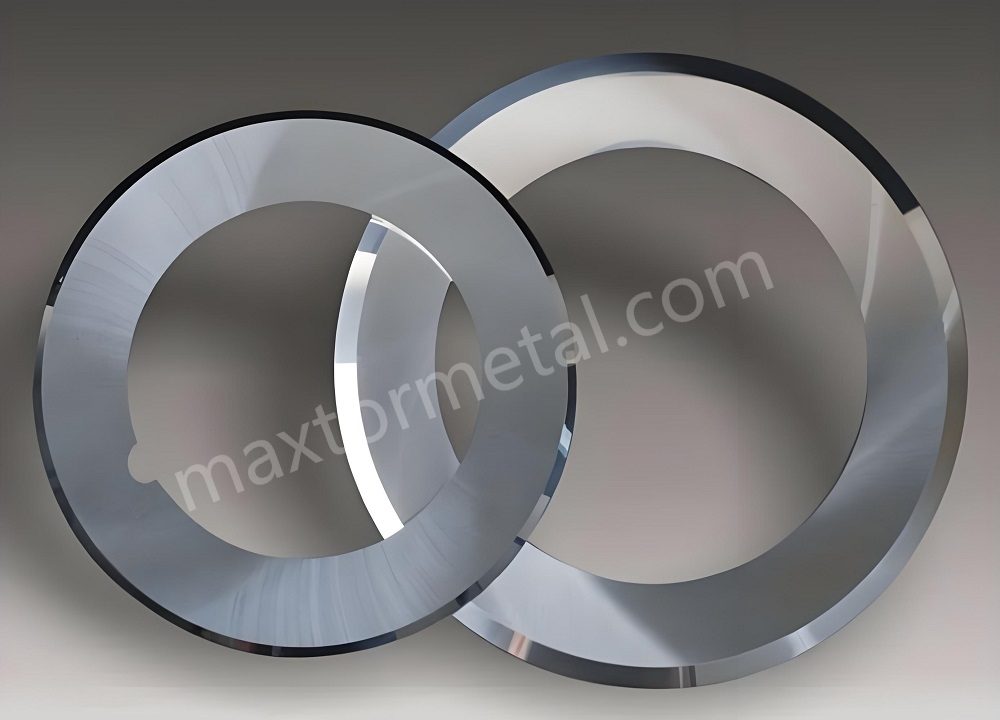
To illustrate how these principles translate to operating performance, consider a continuous, high-volume specialty paper converting plant running on circular shear slitting knives. The line processes approximately 100 tons of roll paper per day in around-the-clock, multi-shift operation, using conventional alloy tool steel circular knives.
| المعلمة | Before Upgrade (Conventional Tool Steel) | After Upgrade (Combined Knife & Process) |
|---|---|---|
| Average blade wear life | خط الأساس | +250% |
| Slitting dust & debris | Severe airborne dust, rough edges, rapid wear | −85% |
| Converting line uptime | Approximately one maintenance stop every 48 h | +40% |
The failure mechanism observed in this case is directly relevant to the root-cause discussion above. On specialty paper containing calcium carbonate, titanium dioxide, and kaolin clay fillers, the original blade edges dulled progressively over the production run. As sharpness was lost, the cut transitioned from true shearing into sliding, crushing, and tearing against the web, releasing substantially more paper dust. High flank surface roughness was likewise identified as one of the three primary tooling problems on this line.
Data source: Publicly reported supplier field case; customer identity and detailed production records were not disclosed. Reported performance should therefore be treated as supplier-reported field data rather than independently audited test data. The reported −85% reduction in dust and debris was achieved after a combined knife-and-process upgrade. Surface finish was one of the controlled variables addressed, rather than an independently isolated cause. Ra < 0.1 µm should be understood as an engineering control target, not a standalone causal explanation for the field result.
This example reinforces that a superfinished mirror-polish blade (Ra < 0.1 µm) is one necessary element of a zero-dust strategy, but it operates within a wider system of sharpness, geometry, and machine condition. The metrology and metallurgy decisions in the next sections define what such a blade must deliver and how to keep it performing over time.
Maxtor Metal’s application engineering team has observed consistent results in this direction across specialty paper and film converting projects: when superfinished blades (Ra < 0.1 µm, PM-M4 substrate) replace standard precision-ground D2 knives under otherwise identical setup conditions, blade-change intervals driven by dust-related quality stops typically extend by a factor of 2–3×. The Ra threshold and metallurgical selection criteria described in this report reflect the same engineering controls applied in those projects.
علم المعادن والبنية المجهرية: اختيار الصلب الذي يحافظ على تشطيب Ra < 0.1 µm
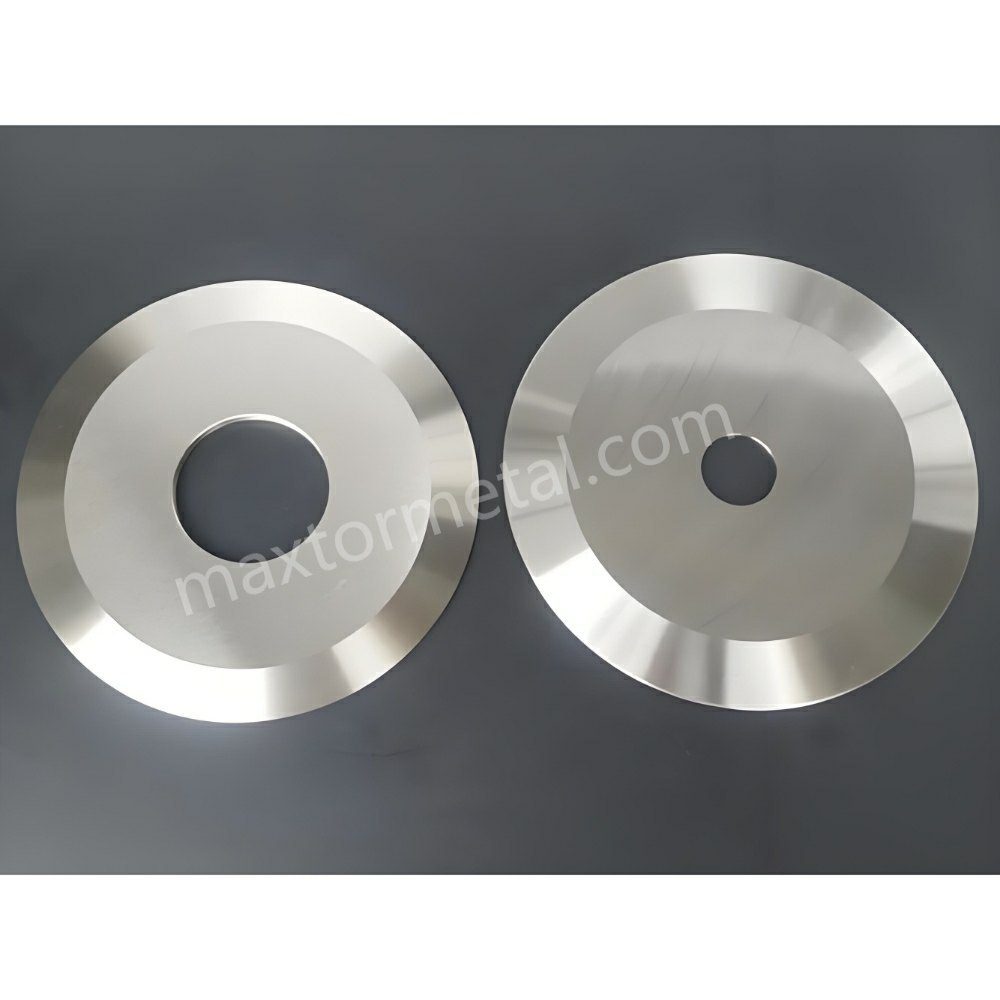
A blade manufacturer can polish an inferior tool steel to a mirror finish in the grinding shop, but if the material’s internal microstructure is unstable, that finish will degrade rapidly under production loads.
The Carbide Pull-Out Pitfall in Conventional D2 / SKD11
Conventional cold-work tool steels like AISI D2 (1.2379 / SKD11) are widely used for industrial cutlery due to their high chromium and carbon content. However, ingot-cast D2 contains large, primary eutectic chromium carbides (M₇C_3) measuring 15 µm to 30 µm in size.
When grinding technicians attempt to superfinish D2 down to Ra < 0.1 µm, the diamond lapping wheel catches these large, brittle carbides and tears them out of the softer martensitic matrix. This phenomenon, known as carbide pull-out, leaves microscopic pits across the blade flank. These micro-pits collect debris and create sharp cavity edges that act as abrasive sites during high-speed slitting.
Powder Metallurgy (PM) and Fine-Grain Carbide Solutions
To maintain an Ra < 0.1 µm surface without carbide pull-out, converting operations must transition to advanced metallurgical alloys.[3] Powder-metallurgy grades such as PM-M4 provide a fine, uniformly distributed vanadium-carbide structure that is far more suited to ultra-fine finishing than the coarse chromium-carbide clusters found in conventional D2.
- Powder Metallurgy Steels (PM-M4, PM-A11 / CPM 10V): Produced via gas atomization and hot isostatic pressing (HIP), PM steels feature ultrafine, spherical vanadium carbides (VC) evenly distributed throughout the matrix. Carbide sizes remain under 2 µm, enabling continuous lapping to Ra < 0.05 µm without micro-pitting.
- Micro-Grain Tungsten Carbide: For high-abrasion applications (lithium-ion battery separator films, glass-filled non-wovens), fine-grain tungsten carbide (0.5–0.8 µm grain size) with 10–12% cobalt binder provides extreme hardness (HRC 75–80) while maintaining a flawless mirror finish over months of continuous operation.
Processing plants requiring high-durability tooling can explore industrial circular slitter blades crafted from powder metallurgy and micro-grain tungsten carbide alloys.
| Steel Grade Comparison for Superfinishing Retention | Detail |
|---|---|
| Conventional D2 / SKD11 | Coarse Carbides 20µm → Carbide Pull-Out → Micro-Pitting (Ra Degrades) |
| PM-M4 / CPM 10V Steel | Fine Carbides < 2µm → Smooth Lapping → Retains Ra < 0.1 µm Finish |
| Tungsten Carbide (Fine) | Sub-Micron Grains → Mirror Polish → Maximum Wear & Zero Dust |
Deep Cryogenic Treatment (-185°C)
After vacuum heat treatment and triple tempering, premium circular knives undergo deep cryogenic treatment at -185°C (-300°F) for 24 hours. Cryogenic processing converts residual retained austenite into stable martensite while precipitating microscopic eta-carbides. This stabilizes the steel matrix, preventing dimensional distortion and preventing stress-induced surface roughening during high-speed rotation. The sequence in which cryogenic treatment, heat treatment, and final lapping are ordered matters as much as the treatment parameters themselves — this process discipline is covered in the next section.
A First-Party Engineering Perspective: Why Finish Retention Outlasts Finish Achievability
A common misconception among converters is that an Ra < 0.1 µm mirror polish is simply a grinding-shop deliverable. In practice, the harder problem is retention under service — keeping that finish through heat treatment, handling, mounting, and high-speed contact. This is where process sequence matters more than the final grinding pass.
From Maxtor Metal’s own shop-floor experience across paper, plastics, and metal-slitting lines, three sequence decisions consistently separate blades that hold a mirror finish from blades that merely start with one:
- Cryogenics Before Lapping: When deep cryogenic stabilization precedes ultra-fine diamond lapping, the austenite-to-martensite conversion is complete before final grinding. Lapping then acts on a dimensionally stable matrix, so the polished surface does not “rewarp” or shed as-transformed carbides in service. Sequence these steps in the reverse order and the finish is vulnerable to surface roughening within weeks of operation.
- Finish Ground on the Mounting Reference, Not as a Standalone Blank: Superfinished flanks are most stable when lapped after the bore and lateral faces are final-ground to their ±0.001 mm tolerances (see the runout section). Lapping a blank first, then grinding the bore, risks re-introducing micro-distortion at the very flank that defines dust performance.
- Documented Material Traceability: Requiring EN 10204 Type 3.1 mill certificates and batch-level traceability means the carbide distribution — and therefore the finish-retention capability — is verifiable on paper, not just on the surface. This turns an otherwise invisible metallurgical claim into an auditable control variable.
These sequencing principles are not found in generic tool-grade datasheets; they reflect first-party process knowledge accumulated through dedicated zero-dust converting programs. For teams planning a Ra < 0.1 µm upgrade, treating the process order with the same rigor as the final Ra number is the single most practical lever for lasting, measurable dust reduction.
مصفوفة ضبط الماكينة: التحكم في العوامل الثانوية لشوائب التقطيع
While specifying superfinished blades with Ra < 0.1 µm removes the primary cause of dust, incorrect machine setup can force even the best knife to rub against the web, reintroducing debris.
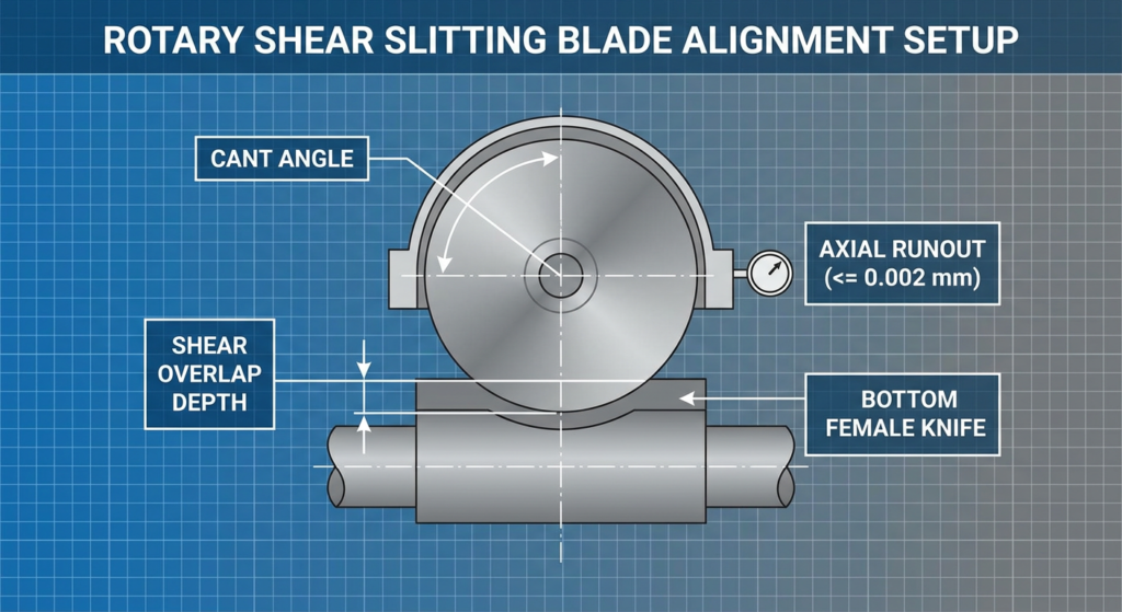
Shear Overlap Depth and Cant Angle Calibration
The interaction between the top circular knife and bottom female slitter must mimic a precise pair of scissors:
- Cant Angle (Side Angle): The angle at which the top dished blade leans into the bottom knife band. Too high a cant angle (> 1.0°) causes excessive point-loading, accelerating flank wear and creating steel dust. Too low an angle (< 0.2°) leads to blade separation and web tearing. For superfinished blades, maintain a cant angle between 0.35° and 0.50°. Maxtor Metal’s field engineering team uses this window as the commissioning baseline when setting up superfinished circular knives on film and nonwoven slitting lines; angles outside this range are the most common setup cause of premature mirror-finish degradation in the first 48 hours of production.
- Shear Overlap Depth: Top blade penetration into the bottom ring should be kept to the minimum required for a clean cut (typically 0.5 mm to 0.8 mm for films under 200 microns). Excessive overlap increases the contact arc distance between the weband the blade flank, increasing rubbing and dust generation. For a detailedtreatment of how overlap, cant angle, and preload interact during shearslitting setup, see إعداد زنبركي لقص القطع بدون خلوص: التحكم في التداخل وزاوية الميل والتحميل المسبق. For a DOE-based analysis of how overlap depth and side clearance trade off against each other across substrate families—with Pareto data on edge quality vs knife life—see تحسين عمق تداخل السكين الدائري والخلوص الجانبي.
Axial Runout Control (≤ 0.002 mm) and Spindle Alignment
If the slitter arbor or knife holder exhibits axial wobble (runout), the shear clearance fluctuates with every rotation. This dynamic wobble forces the blade flank to slap against the slit edge twice per revolution, causing cyclic micro-fractures and periodic dust spikes.
Top dished knives and female bottom slitter knives must be ground with lateral thickness tolerances of ± 0.001 mm and mounted on precision-ground expansion arbors to ensure total axial runout remains ≤ 0.002 mm. On multi-knife gang setups, this ±0.001 mm per-knife tolerance accumulates across the arbor stack—a small per-blade variance can shift calibrated shear clearance by enough to trigger secondary rubbing and dust across multiple lanes. For the stack-up math and spacer-matching discipline that prevents this, see التحكم في التفاوت التراكمي في السماكة في عملية القطع متعددة الشفرات.
Maxtor Metal verifies axial runout on all finished circular slitting knife assemblies against this ≤ 0.002 mm threshold as a final inspection gate, with results documented in the batch inspection record.
For a measurement-first approach to diagnosing the axial and radial TIR components that drive these dust spikes—including cold-to-hot drift verification and the defect signatures each runout mode produces—see الانحراف المحوري، والانعكاس الكلي الداخلي الديناميكي، وجودة حافة الشق.
For the upstream bore-fit decisions that establish the locating baseline from which axial runout is controlled—ISO 286 H7/h6 vs H7/g6 selection, GD&T coaxiality targets, and assembled TIR verification routines—see التفاوت في قطر التجويف المركزي والانحراف: تحسين تركيبات ISO 286 لسكاكين القطع عالية السرعة.
For lines where runout is also contributing to snake cuts or lane drift, see Stopping Snake Cuts in Film Slitting: A Systems Checklist.
For lines where blade coating is also under consideration alongside surface finish — particularly whether DLC or PTFE coatings affect flank friction and cleaning intervals at the Ra level specified here — see دليل اختيار طلاءات DLC مقابل PTFE لشفرات الشق الدائرية: التآكل مقابل انتقال المواد.
بروتوكول الفحص في أرض المصنع: الصيانة على الشفرات ذات التشطيب الفائق
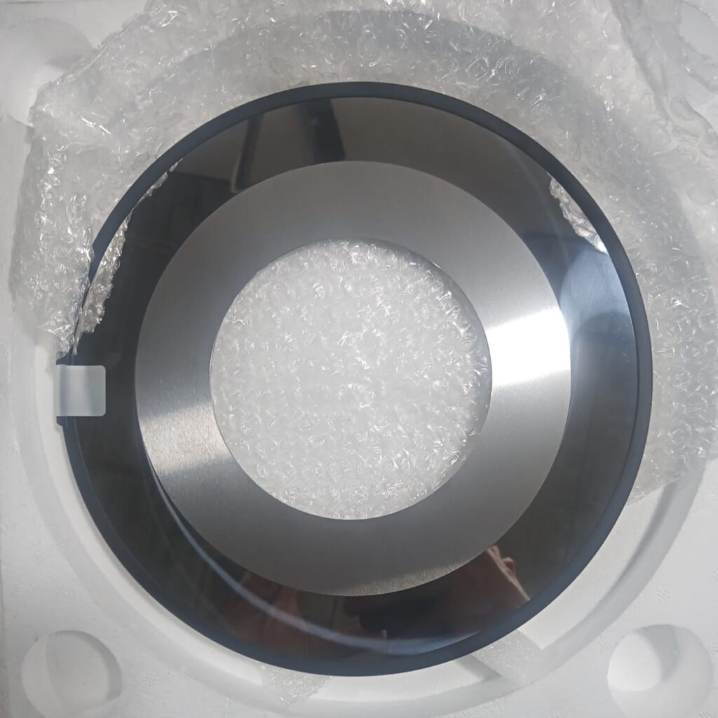
To sustain zero-dust slitting performance across multi-shift production, plant quality teams should adopt a structured inspection routine.
Portable Profilometer Inspection Protocol
- Measurement Location: Take three profilometer readings on the primary bevel flank at 120° intervals around the circular knife.
- Rejection Threshold: If average surface roughness exceeds Ra 0.18 µm or if individual peaks show Rz > 0.6 µm, schedule the blade set for precision re-lapping.
- فحص الحافة: Inspect the cutting edge under a 50x portable shop microscope. Any micro-chipping exceeding 0.005 mm in depth will act as a dust generator and requires regrinding.
Quantifying Dust Reduction: Measurement Protocols That Stand Up to Audit
To make dust-control claims defensible (rather than marketing assertions), converting plants should pair each improvement with structured evidence:
- Profilometer Measurement: Record Ra / Rz on the flank bevel before and after each blade change using a calibrated contact profilometer, averaging at least three traces 120° apart per ISO 4288.
- Edge Microscopy: Capture fixed-magnification (50x–200x) before/after images of the slit edge to document the transition from frayed, roughened edges to clean fracture faces.
- جمع الغبار: Standardize dust sampling at a consistent location and method (for example, a fixed-area tape lift or gravimetric filter catch near the cut point) so results are comparable across blade sets and shifts.
This three-part protocol lets a plant attribute measured dust reduction to the correct variable combination — blade finish, geometry, or process setpoint — rather than overstating the effect of any single control.
Lapping and Precision Regrinding Guidelines
Regrinding superfinished blades on standard toolroom wheel grinders will destroy the Ra < 0.1 µm surface finish. This is consistent with supplier guidance that most converting applications require at least an eight RMS finish, while the highest-speed paper slitting lines demand a super finish of under one RMS to control dust.[4]
- اختيار حجر التجليخ: Use fine vitrified CBN (Cubic Boron Nitride) wheels for PM steels or resin-bond diamond wheels (1200–2000 mesh) for tungsten carbide.
- Secondary Superfinishing: After primary angle grinding, pass the blades through a two-step diamond lapping process using diamond paste (1–3 µm grit) to restore the mirror finish.
- Demagnetization: Demagnetize all blades to under 2 Gauss after grinding. Residual magnetism attracts fine steel and iron dust, which gets carried directly into the web cut zone.
الأسئلة الشائعة
س1: ما هو السبب الرئيسي لتولد غبار التقطيع في خطوط التحويل عالية السرعة؟
يتولد غبار التقطيع بشكل أساسي عن طريق الاحتكاك بين الشريط ورباط/جانب الشفرة. عندما يحتوي جانب الشفرة على حزوز تجليخ خشنة (Ra > 0.4 µm)، فإن هذه البروزات المجهرية كشط وتعتلق بحافة الشريط أثناء حركة المادة نحو الأسفل، مما يسبب تمزقات دقيقة موضعية ويطلق غبارًا دقيقًا من البوليمر أو الألياف.
س2: لماذا تعد الخشونة السطحية لجانب الشفرة (Ra) أكثر أهمية للتحكم في الغبار من حدة الحافة بمفردها؟
تحدد حدة الحافة مدى سهولة بدء الكسر الأولي بالقص، لكن الخشونة السطحية لجانب الشفرة تحكم كيفية تصرف حافة الشريط أثناء انزلاقها عبر الشفرة أثناء الحركة عالية السرعة. الشفرة الحادة جدًا كالموس ذات الجانب الخشن ستستمر في إتلاف وتنسيل حواف الشريط وتوليد غبار كثيف بسبب سحب البروزات المجهرية.
س3: ما هي مواصفات الخشونة السطحية التي يجب أن أطلبها لتقطيع الأفلام الخالي تمامًا من الغبار؟
بالنسبة لأفلام التغليف المرنة (BOPP, PET, PE)، والأقمشة غير المنسوجة التقنية، والرقائق المطلية، حدد تلميعًا مرآويًا فائقا (Superfinished mirror polish) مع Ra < 0.1 µm (2–4 RMS) و Rz < 0.4 µm. هذه هي نفس المواصفات التي تستخدمها Maxtor Metal كحد أدنى للقبول لجميع الشفرات الدائرية الموردة لخطوط تحويل الأفلام والأقمشة غير المنسوجة عالية السرعة.
س4: لماذا يفشل صلب الأدوات التقليدي D2 في الحفاظ على اللمسة النهائية المرآوية أثناء التلميع الفائق (Superfinishing)؟
يحتوي صلب D2 التقليدي على كربيدات كروم أولية كبيرة (15-30 ميكرومتر). أثناء التنعيم الدقيق بالألمظ (Diamond lapping)، تنقلع هذه الكربيدات الكبيرة من مصفوفة الصلب (ظاهرة اقتلاع الكربيدات / Carbide pull-out)، مما يخلق فجوات مجهرية تجمع الحطام وتجعل حافة القطع خشنة. تتجنب صلب ميتالورجيا المساحيق (PM-M4) أو كربيدات التنجستن دقيقة الحبيبات هذه المشكلة بفضل بنيتها الكربيدية دون الميكرونية.
س5: كيف يؤثر الانحراف المحوري (Axial runout) على مستويات غبار التقطيع؟
يؤدي الانحراف المحوري (التذبذب) في عمود الشفرات إلى اتساع وضيق الخلوص الجانبي بين الشفرتين العلوية والسفلية أثناء كل دورة. يتسبب هذا التذبذب الديناميكي في احتكاك وسحق دوري لحافة الشريط، مما يؤدي إلى انبعاثات دورية للغبار وتكون زوائد حادة (Burrs). يجب الحفاظ على الانحراف المحوري عند ≤ 0.002 مم. توثق Maxtor Metal هذا القياس في سجل فحص الدفعة لجميع مجموعات الشفرات الدائرية المكتملة كبوابة فحص نهائية إجبارية.
س6: هل يمكن إعادة إحذاء/تجليخ الشفرات ذات التلميع الفائق (Superfinished) على جلاخات الورش القياسية؟
नहीं। मानक ग्राइंडिंग व्हील खुरदुरे ग्राइंडिंग निशान (Ra 0.4–0.8 µm) छोड़ते हैं जो सुपरफिनिश के लाभों को समाप्त कर देते हैं। Ra < 0.1 µm सतह फिनिश को पुनर्स्थापित करने के लिए पुन: ग्राइंडिंग (regrinding) के बाद महीन CBN या डायमंड कंपाउंड (1–3 µm पेस्ट) का उपयोग करके एक सटीक लैपिंग प्रक्रिया (precision lapping) का पालन किया जाना चाहिए।
الخطوات التالية: ترقية خط التقطيع لديك إلى دقة التقطيع الخالي من الغبار
Eliminating slitting dust generation requires a systematic approach combining advanced tool metallurgy, superfinished surface metrology, and rigid machine alignment. By replacing standard commercial ground knives with superfinished (Ra < 0.1 µm) powder metallurgy circular blades, converting plants can eliminate web edge contamination, prevent optical defect triggers, and extend blade service life.
Maxtor Metal manufactures custom precision-ground circular slitting knives, shear blades, and bottom female bands engineered specifically to eliminate edge debris in high-speed converting. Every blade undergoes deep cryogenic treatment, ultra-fine diamond lapping, and complete material certification (EN 10204 Type 3.1) to guarantee consistent, zero-dust performance.
Quality is verified through an independently audited framework. The company is certified to ايزو 9001 (quality management systems) and holds SGS third-party inspection certification, and production runs under an ISO-based “in-line” quality assurance regime with a multi-stage inspection gate (first-article, incoming material, in-process, and final inspection) on every order. These externally audited credentials give engineers a documented assurance trail that mirrors the root-cause discipline described throughout this report.
To review technical drawings or request custom knife grinding specifications for your converting line, contact the engineering team at Maxtor Metal.
المراجع
- ISO 4287 — Geometrical product specifications (GPS) — Surface texture: Profile method — Terms, definitions and surface texture parameters; ISO 4288 — Rules and procedures for the assessment of surface texture.
- TAPPI (Technical Association of the Pulp and Paper Industry), Troubleshooting slitter blade wear — blade edge smoothness and ground surface finish criteria relevant to slit quality and dust generation on slitting lines; and TAPPI, Roll and Web Defect Terminology (Chapter 5: Slitter Defects), which classifies slitter dust and edge-quality defects such as fuzzy edge and dust in roll.
- Powder metallurgy high-speed and tool-steel grade documentation covering carbide size distribution and finish-holding capability: Z-M4 PM (PM-M4) Tooling Alloys Data Sheet, Zapp Precision Metals; و CPM 10V (AISI A11) Data Sheet, Crucible Industries.
- Industry converting references on knife surface-finish requirements: TAPPI, Troubleshooting slitter blade wear (ground surface finish not exceeding 16 micro-inches for utility slitting); and Converting Quarterly, Ten web defects due to slitting (very smooth knife surface finish — 8 RMS or lower — to reduce excessive dust creation).
- ايزو 9001:2015 — Quality management systems — Requirements (ISO international standards catalog). Maxtor Metal’s quality management is certified to ISO 9001 and additionally verified through SGS third-party inspection.
- ISO 21940-11 — Mechanical vibration — Rotor balancing — Part 11: Procedures and tolerances for rotors with rigid behaviour، و ISO 20816-1 — Mechanical vibration — Measurement and evaluation of machine vibration, as applied to slitter arbor balancing and spindle condition.
- EN 10204 — Metallic products — Types of inspection documents (Type 3.1 mill certificate with batch-level material traceability). Official European standard; catalog/purchase entry via national standards body: NEN-EN 10204:2004 (Netherlands Standardization Institute).
- Maxtor Metal in-house quality assurance regime — ISO-based “in-line” inspection including first-article, incoming material, in-process, and final inspection on precision-ground circular slitting knives.
حول المؤلف
جيري تشو — Technical Support Specialist, After-sales Service, Maxtor Metal
With 10 years of cross-industry application experience spanning paper, plastics crushing, metal slitting, and wood processing, Jerry specializes in diagnosing on-site cutting issues such as edge burr formation and excessive dust generation. He holds PMP and CMRP certifications, bringing project-management rigor and reliability-engineering perspective to blade selection and line optimization. For field troubleshooting support, contact Maxtor Metal’s after-sales engineering team.

 English
  Spanish
  Italian
  French
  Portuguese
  Russian
  German
  Arabic
  Hindi
Hindi  Vietnamese
  Indonesian
  Japanese
  Korean