

Punti chiave:
- Primary MechanismLa formazione di polvere di taglio non è dovuta semplicemente a un tagliente smussato; è causata principalmente dall'attrito delle micro-asperità sul fianco della lama che strisciano contro il bordo del nastro appena fratturato.
- The Metrology ThresholdRidurre la ruvidezza superficiale del fianco della lama dai livelli commerciali standard (Ra 0,4–0,8 µm) a una lucidatura a specchio con superfinitura (Ra < 0,1 µm) riduce la micro-frizione fino al 60%, bloccando il rilascio di particelle sulle linee ad alta velocità.
- Metallurgical SelectionL'acciaio convenzionale D2 o SKD11 soffre di pull-out dei carburi durante la superfinitura. Raggiungere e mantenere una finitura Ra < 0,1 µm sotto tensione continua del nastro richiede acciai da utensili da metallurgia delle polveri (PM-M4) o carburo di tungsteno sub-micronico.
- Systemic PrecisionLe lame con finitura a specchio devono essere abbinate a rigide tolleranze di montaggio meccanico, tra cui un runout assiale ≤ 0,002 mm, angoli di spoglia corretti e una profondità di sormonto di taglio calibrata per evitare lo sfregamento secondario.
Questi quattro principi costituiscono il framework ingegneristico che il team applicativo di Maxtor Metal applica nella qualificazione delle lame circolari da taglio per programmi di trasformazione a zero polvere in linee di imballaggio flessibile, Tessuto Non Tessuto (TNT) e carte speciali.
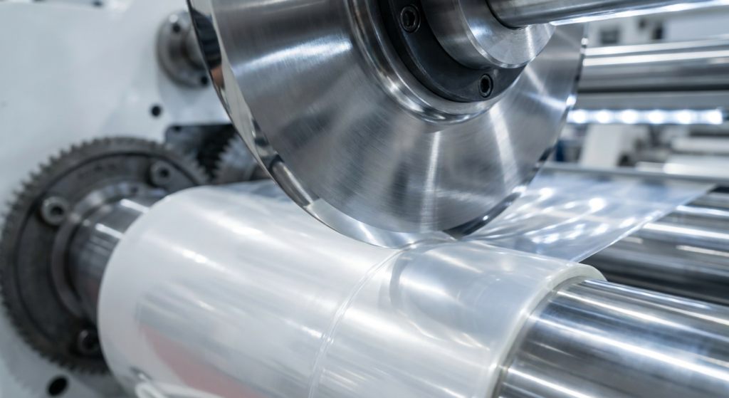
Nella trasformazione ad alta velocità di imballaggi flessibili, tessili tecnici, Tessuto Non Tessuto (TNT) e carte speciali, la contaminazione da particolato è una delle principali cause di fermi linea non programmati. Ciò che gli operatori di impianto diagnosticano frequentemente come "tensione errata del nastro" o "rotolo di materia prima difettoso" spesso risale a un'unica causa radice: la formazione di polvere di taglio che si verifica proprio nel punto di taglio a forbice.
Quando scaglie microscopiche di polimero, frammenti di fibra o particelle di rivestimento inorganico si accumulano sui rotoli di nastro tagliato, i processi a valle vanno in crisi. I sistemi di ispezione ottica attivano falsi allarmi di difettosità, gli inchiostri da stampa sviluppano micro-fori (pinholes) a causa dei vuoti generati dalla polvere, e i rotoli caricati elettrostaticamente intrappolano aria, causando il telescopaggio durante l'avvolgimento.
Sebbene le tradizionali pratiche di manutenzione si concentrino quasi esclusivamente sull'affilatura della lama (raggio del tagliente), la ricerca tribologica e la metrologia di officina dimostrano che il raggio del tagliente è solo metà del problema. Il fattore principale del rilascio di polveri sottili è il profilo di ruvidezza superficiale del fianco della lama.
Questo report tecnico esamina la meccanica della zona di taglio nel processo di taglio rotativo a forbice, quantifica l'impatto dei parametri di ruvidezza superficiale (Ra, Rz, Rmax), valuta le microstrutture degli acciai da utensili e delinea i parametri operativi necessari per ottenere prestazioni di taglio a zero polvere.
La micromeccanica della polvere di taglio: come la ruvidezza del fianco innesca l'erosione del nastro
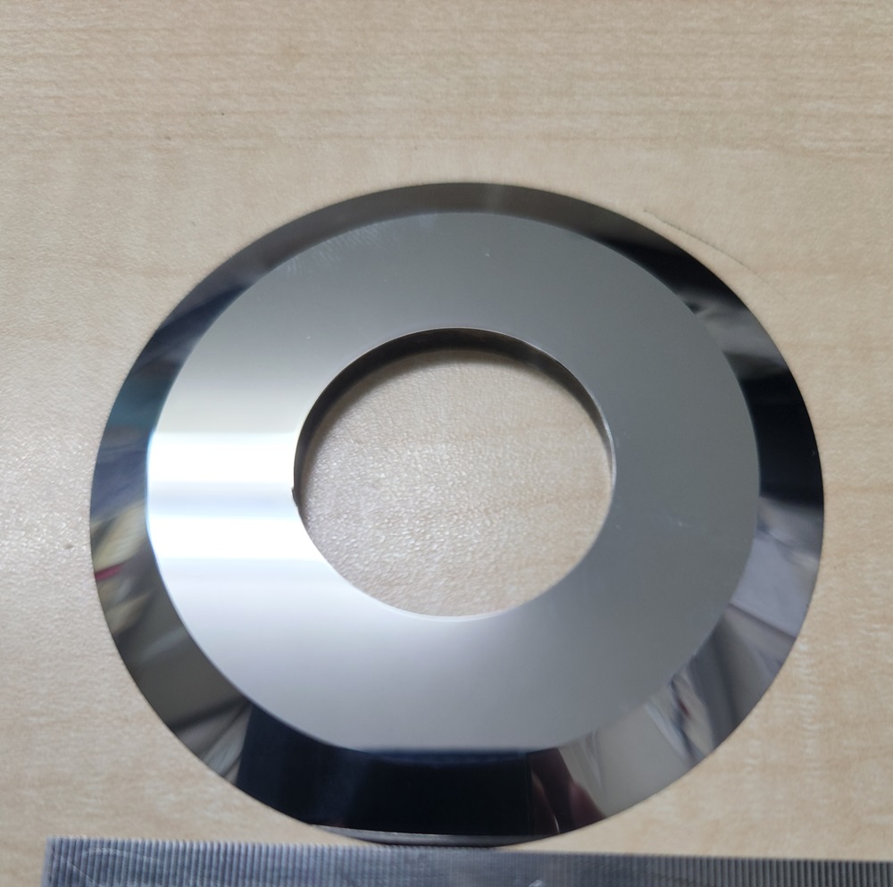
To eliminate particulate contamination, converting process engineers must analyze the two-stage shear slitting sequence. Shear slitting is not a simple razor slicing action; it is a controlled mechanical fracture occurring between an upper dished circular knife and a lower female slitter band.
Stage 1: Elastic-Plastic Compression → Material is squeezed between upper & lower blade edges.
Stage 2: Micro-Cleavage Initiation  → Shear stress exceeds ultimate yield strength; crack propagates.
Stage 3: Flank Contact & Web Travel  → Fractured web edge slides along the upper blade flank downweb.
Micro-Asperity Drag vs. Clean Shear Fracture
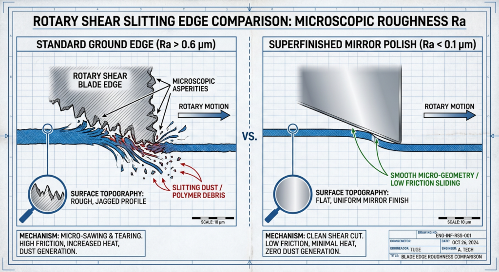
During Stage 3, the newly created web edge travels along the side flank of the top circular blade. When a blade is ground using standard production wheels, the grinding wheel leaves directional ridges called micro-asperities.
Under 200x optical magnification, a standard ground blade flank resembles a microscopic saw. As the web edge moves past these peaks at speeds exceeding 300 meters per minute, the asperities snag individual polymer chains or cellulosic fibers. Rather than parting cleanly, the material experiences localized micro-tearing, abrasion, and shear deformation. The torn material detaches as fine airborne particulates or static-bound debris. This matches engineering documentation from leading slitting-knife suppliers, which notes that rough blade surfaces fray slit edges as the web traverses the flank, and that regrinding quality can increase dust even when the measured finish appears similar.[2]
The Three-Body Abrasive Wear Feedback Loop
Once initial dust particles detach, they trigger a accelerating degradation cycle:
- Particle Entrapment: Fine debris lodges in the micro-clearance gap between the upper blade bevel and lower female knife ring. The bevel geometry at the upper knife tip also determines how much contact area is exposed to this three-body abrasive loop. A compound micro-bevel reinforces the tip against particle-induced chipping while reducing the exposed flank surface—for a rigidity-led bevel selection framework, see Smussature singole, doppie e composte per lame circolari da taglio.
- Three-Body Abrasion: Trapped hard particles (such as calcium carbonate fillers in plastic films or titanium dioxide pigments in non-wovens) act as an abrasive lapping compound.
- Flank Scuffing & Dullness: The debris scuffs the blade flank, increasing surface roughness while rounding the primary cutting edge.
- Exponential Dust Spike: As the blade surface roughens and dulls, the depth of material tearing increases, generating larger volumes of dust.
Material Substrate Sensitivity
Different converting substrates exhibit distinct failure modes when exposed to rough blade flanks:
- BOPP, PET & PE Films: High friction generates localized thermal energy at the cut boundary. Friction-induced heating causes micro-melting followed by brittle thermal fracturing, producing fine white polymer powder.
- Non-Wovens & Synthetic Textiles: Micro-asperities catch individual filaments, pulling them out of the bonded matrix (fiber fraying) rather than shearing them.
- Coated Papers & Paperboard: Rough flanks crack the inorganic top coat (clay/latex), releasing mineral dust that rapidly abrades tool steel edges.
Analisi della metrologia superficiale: perché Ra < 0,1 µm è la soglia per il taglio a zero polvere
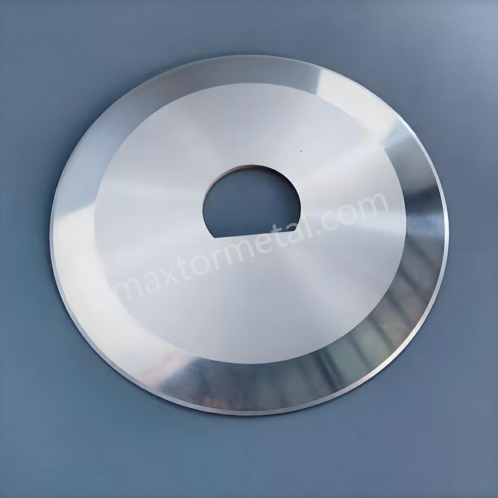
Quantifying surface finish requires moving beyond subjective terms like “polished” or “bright finish.” Plant managers must specify surface metrology parameters using profilometer testing under the ISO 4287 series, which defines the Ra, Rz, and Rmax profile parameters, and ISO 4288, which governs how measured values are compared against tolerance limits.[1]
- Ra (Center Line Average): The arithmetic average of profile height deviations from the mean line.
- Rz (Average Maximum Height): The average peak-to-valley height of five consecutive sampling lengths.
- Rmax: The maximum individual peak-to-valley distance across the entire evaluation length.
In rotary slitting, Ra directly governs steady-state friction, while Rz dictates whether peak asperities will snag substrate fibers.
| Surface Finish Category | Surface Roughness (Ra) | Peak-to-Valley (Rz) | Surface Topography Profile | Slitting Dust Generation Level | Typical Conversion Fit & Limits |
|---|---|---|---|---|---|
| Commercial Ground | Ra 0.4 – 0.8 µm (16–32 RMS) | Rz 1.6 – 3.2 µm | Pronounced circumferential grinding marks; aggressive micro-peaks. | Severe: Continuous polymer flaking and fiber fraying. | Thick rubber trimming or low-speed corrugated board. Unsuitable for films. |
| Precision Ground | Ra 0.2 – 0.4 µm (8–16 RMS) | Rz 0.8 – 1.6 µm | Fine grinding lines; moderate peak height reduction. | Moderate: Acceptable for paperboard under 150 m/min; creates static dust on thin films. | Standard paper converting and basic packaging lines. |
| Superfinished Mirror Polish | Ra < 0.1 µm (2–4 RMS) | Rz < 0.4 µm | Near-frictionless mirror topography; zero directional grinding ridges. | Near-Zero: Smooth sliding contact with clean shear fracture and no material drag. | High-speed BOPP/PET film, battery separators, non-wovens, and medical foils. |
When upgrading from a precision ground finish (Ra 0.3 µm) to a superfinished mirror finish (Ra < 0.1 µm), the kinetic coefficient of friction between the blade flank and web can drop by approximately 50% to 60% in controlled tribometer testing on precision-ground tool steel — a range consistent with Maxtor Metal’s internal comparative testing between Ra 0.3 µm and Ra < 0.1 µm PM-M4 samples under simulated slitting contact conditions.. This reduction helps keep steady-state flank contact below the critical shear stress required to tear material off the cut edge, reducing slitting dust generation at the source.
It is important to frame this threshold correctly. As documented in industry converting engineering guidance, dust generation is not governed by surface finish alone. Engineering references identify several interacting variables that together determine how much dust a line produces: blade sharpness, shear (cant) angle, side load, web material, knife rotational speed, overlap, runout, and web tension. A superfinished blade reduces the flank-driven component of dust, but it must be combined with correct setup geometry to deliver near-zero shedding in production.
Engineers evaluating high-performance converting lines can review precision-ground shear blades and rotary slitting knives to verify how superfinished surface metrology contributes to micro-asperity drag elimination.
Caso studio sul campo: trasformazione di carta speciale ad alta produttività
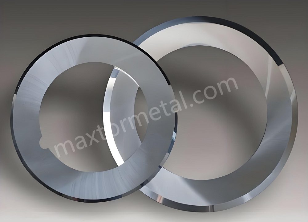
To illustrate how these principles translate to operating performance, consider a continuous, high-volume specialty paper converting plant running on circular shear slitting knives. The line processes approximately 100 tons of roll paper per day in around-the-clock, multi-shift operation, using conventional alloy tool steel circular knives.
| Parametro | Before Upgrade (Conventional Tool Steel) | After Upgrade (Combined Knife & Process) |
|---|---|---|
| Average blade wear life | Linea di base | +250% |
| Slitting dust & debris | Severe airborne dust, rough edges, rapid wear | −85% |
| Converting line uptime | Approximately one maintenance stop every 48 h | +40% |
The failure mechanism observed in this case is directly relevant to the root-cause discussion above. On specialty paper containing calcium carbonate, titanium dioxide, and kaolin clay fillers, the original blade edges dulled progressively over the production run. As sharpness was lost, the cut transitioned from true shearing into sliding, crushing, and tearing against the web, releasing substantially more paper dust. High flank surface roughness was likewise identified as one of the three primary tooling problems on this line.
Data source: Publicly reported supplier field case; customer identity and detailed production records were not disclosed. Reported performance should therefore be treated as supplier-reported field data rather than independently audited test data. The reported −85% reduction in dust and debris was achieved after a combined knife-and-process upgrade. Surface finish was one of the controlled variables addressed, rather than an independently isolated cause. Ra < 0.1 µm should be understood as an engineering control target, not a standalone causal explanation for the field result.
This example reinforces that a superfinished mirror-polish blade (Ra < 0.1 µm) is one necessary element of a zero-dust strategy, but it operates within a wider system of sharpness, geometry, and machine condition. The metrology and metallurgy decisions in the next sections define what such a blade must deliver and how to keep it performing over time.
Maxtor Metal’s application engineering team has observed consistent results in this direction across specialty paper and film converting projects: when superfinished blades (Ra < 0.1 µm, PM-M4 substrate) replace standard precision-ground D2 knives under otherwise identical setup conditions, blade-change intervals driven by dust-related quality stops typically extend by a factor of 2–3×. The Ra threshold and metallurgical selection criteria described in this report reflect the same engineering controls applied in those projects.
Metallurgia e microstruttura: selezione degli acciai che mantengono una finitura Ra < 0,1 µm
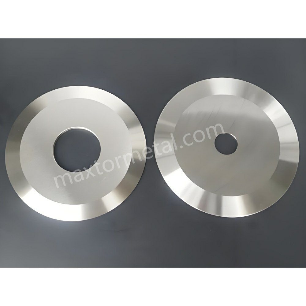
A blade manufacturer can polish an inferior tool steel to a mirror finish in the grinding shop, but if the material’s internal microstructure is unstable, that finish will degrade rapidly under production loads.
The Carbide Pull-Out Pitfall in Conventional D2 / SKD11
Conventional cold-work tool steels like AISI D2 (1.2379 / SKD11) are widely used for industrial cutlery due to their high chromium and carbon content. However, ingot-cast D2 contains large, primary eutectic chromium carbides (M₇C_3) measuring 15 µm to 30 µm in size.
When grinding technicians attempt to superfinish D2 down to Ra < 0.1 µm, the diamond lapping wheel catches these large, brittle carbides and tears them out of the softer martensitic matrix. This phenomenon, known as carbide pull-out, leaves microscopic pits across the blade flank. These micro-pits collect debris and create sharp cavity edges that act as abrasive sites during high-speed slitting.
Powder Metallurgy (PM) and Fine-Grain Carbide Solutions
To maintain an Ra < 0.1 µm surface without carbide pull-out, converting operations must transition to advanced metallurgical alloys.[3] Powder-metallurgy grades such as PM-M4 provide a fine, uniformly distributed vanadium-carbide structure that is far more suited to ultra-fine finishing than the coarse chromium-carbide clusters found in conventional D2.
- Powder Metallurgy Steels (PM-M4, PM-A11 / CPM 10V): Produced via gas atomization and hot isostatic pressing (HIP), PM steels feature ultrafine, spherical vanadium carbides (VC) evenly distributed throughout the matrix. Carbide sizes remain under 2 µm, enabling continuous lapping to Ra < 0.05 µm without micro-pitting.
- Micro-Grain Tungsten Carbide: For high-abrasion applications (lithium-ion battery separator films, glass-filled non-wovens), fine-grain tungsten carbide (0.5–0.8 µm grain size) with 10–12% cobalt binder provides extreme hardness (HRC 75–80) while maintaining a flawless mirror finish over months of continuous operation.
Processing plants requiring high-durability tooling can explore industrial circular slitter blades crafted from powder metallurgy and micro-grain tungsten carbide alloys.
| Steel Grade Comparison for Superfinishing Retention | Detail |
|---|---|
| Conventional D2 / SKD11 | Coarse Carbides 20µm → Carbide Pull-Out → Micro-Pitting (Ra Degrades) |
| PM-M4 / CPM 10V Steel | Fine Carbides < 2µm → Smooth Lapping → Retains Ra < 0.1 µm Finish |
| Tungsten Carbide (Fine) | Sub-Micron Grains → Mirror Polish → Maximum Wear & Zero Dust |
Deep Cryogenic Treatment (-185°C)
After vacuum heat treatment and triple tempering, premium circular knives undergo deep cryogenic treatment at -185°C (-300°F) for 24 hours. Cryogenic processing converts residual retained austenite into stable martensite while precipitating microscopic eta-carbides. This stabilizes the steel matrix, preventing dimensional distortion and preventing stress-induced surface roughening during high-speed rotation. The sequence in which cryogenic treatment, heat treatment, and final lapping are ordered matters as much as the treatment parameters themselves — this process discipline is covered in the next section.
A First-Party Engineering Perspective: Why Finish Retention Outlasts Finish Achievability
A common misconception among converters is that an Ra < 0.1 µm mirror polish is simply a grinding-shop deliverable. In practice, the harder problem is retention under service — keeping that finish through heat treatment, handling, mounting, and high-speed contact. This is where process sequence matters more than the final grinding pass.
From Maxtor Metal’s own shop-floor experience across paper, plastics, and metal-slitting lines, three sequence decisions consistently separate blades that hold a mirror finish from blades that merely start with one:
- Cryogenics Before Lapping: When deep cryogenic stabilization precedes ultra-fine diamond lapping, the austenite-to-martensite conversion is complete before final grinding. Lapping then acts on a dimensionally stable matrix, so the polished surface does not “rewarp” or shed as-transformed carbides in service. Sequence these steps in the reverse order and the finish is vulnerable to surface roughening within weeks of operation.
- Finish Ground on the Mounting Reference, Not as a Standalone Blank: Superfinished flanks are most stable when lapped after the bore and lateral faces are final-ground to their ±0.001 mm tolerances (see the runout section). Lapping a blank first, then grinding the bore, risks re-introducing micro-distortion at the very flank that defines dust performance.
- Documented Material Traceability: Requiring EN 10204 Type 3.1 mill certificates and batch-level traceability means the carbide distribution — and therefore the finish-retention capability — is verifiable on paper, not just on the surface. This turns an otherwise invisible metallurgical claim into an auditable control variable.
These sequencing principles are not found in generic tool-grade datasheets; they reflect first-party process knowledge accumulated through dedicated zero-dust converting programs. For teams planning a Ra < 0.1 µm upgrade, treating the process order with the same rigor as the final Ra number is the single most practical lever for lasting, measurable dust reduction.
Matrice di configurazione macchina: controllo dei fattori secondari nei detriti di taglio
While specifying superfinished blades with Ra < 0.1 µm removes the primary cause of dust, incorrect machine setup can force even the best knife to rub against the web, reintroducing debris.
Shear Overlap Depth and Cant Angle Calibration
The interaction between the top circular knife and bottom female slitter must mimic a precise pair of scissors:
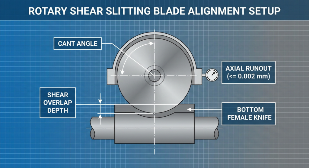
- Cant Angle (Side Angle): The angle at which the top dished blade leans into the bottom knife band. Too high a cant angle (> 1.0°) causes excessive point-loading, accelerating flank wear and creating steel dust. Too low an angle (< 0.2°) leads to blade separation and web tearing. For superfinished blades, maintain a cant angle between 0.35° and 0.50°. Maxtor Metal’s field engineering team uses this window as the commissioning baseline when setting up superfinished circular knives on film and nonwoven slitting lines; angles outside this range are the most common setup cause of premature mirror-finish degradation in the first 48 hours of production.
- Shear Overlap Depth: Top blade penetration into the bottom ring should be kept to the minimum required for a clean cut (typically 0.5 mm to 0.8 mm for films under 200 microns). Excessive overlap increases the contact arc distance between the weband the blade flank, increasing rubbing and dust generation. For a detailedtreatment of how overlap, cant angle, and preload interact during shearslitting setup, see Sistema di fissaggio a molla per taglio a cesoia a gioco zero: controllo di sovrapposizione, angolo di inclinazione e precarico.. For a DOE-based analysis of how overlap depth and side clearance trade off against each other across substrate families—with Pareto data on edge quality vs knife life—see Ottimizzazione della profondità di sovrapposizione e dello spazio laterale della lama circolare.
Axial Runout Control (≤ 0.002 mm) and Spindle Alignment
If the slitter arbor or knife holder exhibits axial wobble (runout), the shear clearance fluctuates with every rotation. This dynamic wobble forces the blade flank to slap against the slit edge twice per revolution, causing cyclic micro-fractures and periodic dust spikes.
Top dished knives and female bottom slitter knives must be ground with lateral thickness tolerances of ± 0.001 mm and mounted on precision-ground expansion arbors to ensure total axial runout remains ≤ 0.002 mm. On multi-knife gang setups, this ±0.001 mm per-knife tolerance accumulates across the arbor stack—a small per-blade variance can shift calibrated shear clearance by enough to trigger secondary rubbing and dust across multiple lanes. For the stack-up math and spacer-matching discipline that prevents this, see Controllo della tolleranza cumulativa dello spessore nel taglio a più lame.
Maxtor Metal verifies axial runout on all finished circular slitting knife assemblies against this ≤ 0.002 mm threshold as a final inspection gate, with results documented in the batch inspection record.
For a measurement-first approach to diagnosing the axial and radial TIR components that drive these dust spikes—including cold-to-hot drift verification and the defect signatures each runout mode produces—see Axial Runout, Dynamic TIR, and Slit Edge Quality.
For the upstream bore-fit decisions that establish the locating baseline from which axial runout is controlled—ISO 286 H7/h6 vs H7/g6 selection, GD&T coaxiality targets, and assembled TIR verification routines—see Tolleranza e concentricità del foro centrale: ottimizzazione degli accoppiamenti ISO 286 per lame da taglio ad alta velocità.
For lines where runout is also contributing to snake cuts or lane drift, see Come evitare tagli a serpente nel taglio della pellicola: una checklist di sistema.
For lines where blade coating is also under consideration alongside surface finish — particularly whether DLC or PTFE coatings affect flank friction and cleaning intervals at the Ra level specified here — see Guida alla Scelta dei Rivestimenti DLC vs PTFE per Lame Circolari e Taglierine: Limiti di Usura vs Trasferimento.
Protocollo di ispezione in officina: manutenzione delle lame con superfinitura
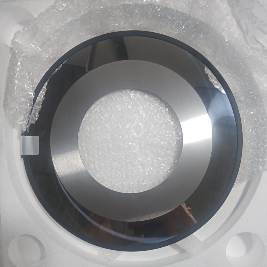
To sustain zero-dust slitting performance across multi-shift production, plant quality teams should adopt a structured inspection routine.
Portable Profilometer Inspection Protocol
- Measurement Location: Take three profilometer readings on the primary bevel flank at 120° intervals around the circular knife.
- Rejection Threshold: If average surface roughness exceeds Ra 0.18 µm or if individual peaks show Rz > 0.6 µm, schedule the blade set for precision re-lapping.
- Edge Inspection: Inspect the cutting edge under a 50x portable shop microscope. Any micro-chipping exceeding 0.005 mm in depth will act as a dust generator and requires regrinding.
Quantifying Dust Reduction: Measurement Protocols That Stand Up to Audit
To make dust-control claims defensible (rather than marketing assertions), converting plants should pair each improvement with structured evidence:
- Profilometer Measurement: Record Ra / Rz on the flank bevel before and after each blade change using a calibrated contact profilometer, averaging at least three traces 120° apart per ISO 4288.
- Edge Microscopy: Capture fixed-magnification (50x–200x) before/after images of the slit edge to document the transition from frayed, roughened edges to clean fracture faces.
- Dust Collection: Standardize dust sampling at a consistent location and method (for example, a fixed-area tape lift or gravimetric filter catch near the cut point) so results are comparable across blade sets and shifts.
This three-part protocol lets a plant attribute measured dust reduction to the correct variable combination — blade finish, geometry, or process setpoint — rather than overstating the effect of any single control.
Lapping and Precision Regrinding Guidelines
Regrinding superfinished blades on standard toolroom wheel grinders will destroy the Ra < 0.1 µm surface finish. This is consistent with supplier guidance that most converting applications require at least an eight RMS finish, while the highest-speed paper slitting lines demand a super finish of under one RMS to control dust.[4]
- Wheel Selection: Use fine vitrified CBN (Cubic Boron Nitride) wheels for PM steels or resin-bond diamond wheels (1200–2000 mesh) for tungsten carbide.
- Secondary Superfinishing: After primary angle grinding, pass the blades through a two-step diamond lapping process using diamond paste (1–3 µm grit) to restore the mirror finish.
- Demagnetization: Demagnetize all blades to under 2 Gauss after grinding. Residual magnetism attracts fine steel and iron dust, which gets carried directly into the web cut zone.
Domande frequenti (FAQ)
D1: Qual è la causa principale della formazione di polvere di taglio sulle linee di trasformazione ad alta velocità?
La polvere di taglio è generata principalmente dall'attrito tra il materiale in nastro e il fianco della lama. Quando il fianco di una lama presenta creste di rettifica ruvide (Ra > 0,4 µm), queste asperità microscopiche abradono e agganciano il bordo del nastro durante lo scorrimento, causando micro-strappi localizzati e rilasciando polveri sottili di polimero o fibra.
D2: Perché la ruvidezza superficiale del fianco della lama (Ra) è più importante per il controllo della polvere rispetto alla sola affilatura del tagliente?
L'affilatura del tagliente determina la facilità con cui si innesca la frattura di taglio iniziale, ma la ruvidezza superficiale del fianco stabilisce il comportamento del bordo del nastro mentre scorre lungo la lama ad alta velocità. Una lama affilata come un rasoio con un fianco ruvido sfilaccerà comunque i bordi del nastro e genererà molta polvere a causa del dragaggio delle microasperità.
D3: Quale specifica di ruvidezza superficiale dovrei richiedere per il taglio di film a zero polvere?
Per i film per imballaggio flessibile (BOPP, PET, PE), i tessuti non tessuti tecnici e i fogli rivestiti, specificare una lucidatura a specchio superfinita con Ra < 0,1 µm (2–4 RMS) e Rz < 0,4 µm. Questa è la stessa specifica che Maxtor Metal utilizza come soglia di accettazione per tutte le lame circolari da taglio fornite alle linee di trasformazione ad alta velocità di film e TNT.
D4: Perché l'acciaio per utensili D2 convenzionale non riesce a mantenere una finitura a specchio durante la lappatura di superfinitura?
L'acciaio D2 convenzionale contiene carburi di cromo primari di grandi dimensioni (15–30 µm). Durante la lappatura diamantata fine, questi grandi carburi si strappano dalla matrice di acciaio (strappo dei carburi / carbide pull-out), creando micro-fori che raccolgono detriti e irruvidiscono il tagliente. Gli acciai da metallurgia delle polveri (PM-M4) o i carburi di tungsteno a grana fine evitano questo problema grazie alla loro struttura di carburi sub-micronica.
D5: In che modo il runout assiale influisce sui livelli di polvere di taglio?
Il runout assiale (oscillazione) sull'albero portalama causa l'apertura e la chiusura del giuoco laterale tra la lama superiore e inferiore durante ogni rotazione. Questa oscillazione dinamica provoca uno sfregamento e uno schiacciamento ciclico contro il bordo del nastro, generando emissioni periodiche di polvere e bave sui bordi. Il runout assiale deve essere contenuto entro ≤ 0,002 mm. Maxtor Metal documenta questa misurazione nel registro di ispezione del lotto per tutti i gruppi di lame circolari finiti come controllo finale obbligatorio.
D6: Le lame con superfinitura possono essere riaffilate su rettificatrici da officina standard?
Non. Les meules de rectification standard laissent des traces de meulage grossières (Ra 0,4–0,8 µm) qui annulent les avantages du superfinition. Le réaffûtage doit être suivi d'un processus de rodage de précision utilisant de la pâte diamantée ou du CBN fin (pâte de 1–3 µm) pour restaurer un état de surface Ra < 0,1 µm.
Passaggi successivi: aggiorna la tua linea di taglio alla precisione a zero polvere
Eliminating slitting dust generation requires a systematic approach combining advanced tool metallurgy, superfinished surface metrology, and rigid machine alignment. By replacing standard commercial ground knives with superfinished (Ra < 0.1 µm) powder metallurgy circular blades, converting plants can eliminate web edge contamination, prevent optical defect triggers, and extend blade service life.
Maxtor Metal manufactures custom precision-ground circular slitting knives, shear blades, and bottom female bands engineered specifically to eliminate edge debris in high-speed converting. Every blade undergoes deep cryogenic treatment, ultra-fine diamond lapping, and complete material certification (EN 10204 Type 3.1) to guarantee consistent, zero-dust performance.
Quality is verified through an independently audited framework. The company is certified to Certificazione ISO 9001 (quality management systems) and holds SGS third-party inspection certification, and production runs under an ISO-based “in-line” quality assurance regime with a multi-stage inspection gate (first-article, incoming material, in-process, and final inspection) on every order. These externally audited credentials give engineers a documented assurance trail that mirrors the root-cause discipline described throughout this report.
To review technical drawings or request custom knife grinding specifications for your converting line, contact the engineering team at Maxtor Metal.
Riferimenti bibliografici
- ISO 4287 — Geometrical product specifications (GPS) — Surface texture: Profile method — Terms, definitions and surface texture parameters; ISO 4288 — Rules and procedures for the assessment of surface texture.
- TAPPI (Technical Association of the Pulp and Paper Industry), Troubleshooting slitter blade wear — blade edge smoothness and ground surface finish criteria relevant to slit quality and dust generation on slitting lines; and TAPPI, Roll and Web Defect Terminology (Chapter 5: Slitter Defects), which classifies slitter dust and edge-quality defects such as fuzzy edge and dust in roll.
- Powder metallurgy high-speed and tool-steel grade documentation covering carbide size distribution and finish-holding capability: Z-M4 PM (PM-M4) Tooling Alloys Data Sheet, Zapp Precision Metals; E CPM 10V (AISI A11) Data Sheet, Crucible Industries.
- Industry converting references on knife surface-finish requirements: TAPPI, Troubleshooting slitter blade wear (ground surface finish not exceeding 16 micro-inches for utility slitting); and Converting Quarterly, Ten web defects due to slitting (very smooth knife surface finish — 8 RMS or lower — to reduce excessive dust creation).
- ISO 9001:2015 — Quality management systems — Requirements (ISO international standards catalog). Maxtor Metal’s quality management is certified to ISO 9001 and additionally verified through SGS third-party inspection.
- ISO 21940-11 — Mechanical vibration — Rotor balancing — Part 11: Procedures and tolerances for rotors with rigid behaviour, E ISO 20816-1 — Mechanical vibration — Measurement and evaluation of machine vibration, as applied to slitter arbor balancing and spindle condition.
- EN 10204 — Metallic products — Types of inspection documents (Type 3.1 mill certificate with batch-level material traceability). Official European standard; catalog/purchase entry via national standards body: NEN-EN 10204:2004 (Netherlands Standardization Institute).
- Maxtor Metal in-house quality assurance regime — ISO-based “in-line” inspection including first-article, incoming material, in-process, and final inspection on precision-ground circular slitting knives.
Informazioni sull'autore
Jerry Chu — Technical Support Specialist, After-sales Service, Maxtor Metal
With 10 years of cross-industry application experience spanning paper, plastics crushing, metal slitting, and wood processing, Jerry specializes in diagnosing on-site cutting issues such as edge burr formation and excessive dust generation. He holds PMP and CMRP certifications, bringing project-management rigor and reliability-engineering perspective to blade selection and line optimization. For field troubleshooting support, contact Maxtor Metal’s after-sales engineering team.

 English
  Spanish
  Italian
  French
  Portuguese
  Russian
  German
  Arabic
  Hindi
Hindi  Vietnamese
  Indonesian
  Japanese
  Korean