Fines and dust rise on water‑strand pelletising lines when three things overlap: unstable cutting mechanics, strands entering the cutter with residual surface water that promotes slippage, and die‑face wear that encourages tails and chipping. Mixed regrind with moisture fluctuation makes each of these more likely: brittle particles within the melt favour micro‑fracture at the cut, moisture spikes cause hydroplaning on the bed knife, and contamination accelerates wear.
“Reducing pelletising fines” isn’t just a housekeeping win; it’s a cost‑per‑tonne lever. Less dust means lower dryer and filter load, steadier downstream feeding, fewer customer complaints over pellet appearance, and reduced rework. On a 1‑tonne‑per‑hour line, cutting fines from 1.2% to 0.6% preserves 6 kg/h of saleable product and typically trims maintenance clean‑downs.
How to use this guide: set the mechanical baselines first (clearance, speed match, alignment), then stabilise water handling and die hygiene, and finally choose blade metallurgy and SOPs matched to your regrind abrasiveness. Validate each change with simple KPIs and keep the cadences tight for the first two weeks.
Conclusiones clave
- Prioritise tight, uniform blade‑to‑bed clearance and match cutter tip speed to line speed to reduce slippage‑driven fines.
- Dewater strands aggressively (>95% free water removed) before cutting; keep bath temperature and length within a controlled window.
- Maintain die‑face flatness and filtration; set an inspection cadence instead of reacting to tails.
- Select wear‑matched blade materials/coatings with traceable hardness and tolerances; regrind to a standard and change over before fines spike.
- Track fines by a standard method, residual moisture, blade life and downtime to prove reductions in cost‑per‑tonne.
Cutting mechanics and speed control
Set blade‑to‑bed clearance
Start tight and uniform, then tune empirically while monitoring fines, tails and motor load. As a starting trial window for strand cutters, many shops begin between 0.05–0.15 mm and tighten towards the lower end only if run‑out, thermal growth and vibration are demonstrably under control. Because OEMs rarely publish universal numbers, treat your machine manual and site safety rules as primary, and treat this window as a practical baseline to validate locally.
From an OEM design standpoint, it’s worth noting that many strand pelletisers are built specifically to let operators “dial in” the rotor‑to‑bed‑knife relationship via mechanical adjustment features—for example, MAAG/Scheer describes eccentric mounting and adjustment to dial the rotor into the bed knife for clean cuts in its Scheer S3500 strand pelletiser brochure (PDF). Some OEM training materials also emphasise fine, incremental bed‑knife adjustment methods to compensate for wear, such as the push/pull bed‑knife approach described in Bay Plastics Machinery’s Basics of Strand Pelletizing training document (PDF).
Check at several clock positions with feeler gauges and verify again after heat‑soak.
Two cautions matter on mixed regrind: first, micro‑hard inclusions can chip an over‑tight edge, so balance clearance with metallurgy (see below). Second, water carry‑over between strand and bed can “float” the cut if the gap is too wide, generating smeared edges and fines.
Match cutter surface speed
Tip speed should closely track strand haul‑off speed to avoid slip‑induced rubbing. A transparent way to set an initial RPM is to match tip speed to line speed and then fine‑tune on load and pellet quality:
- Tip speed (m/min) ≈ π × Drotor (m) × RPM
- Therefore, RPM ≈ line speed / (π × Drotor)
Example: If your line speed is 60 m/min and rotor diameter is 0.20 m, RPM ≈ 60 / (π × 0.20) ≈ 95.5 rpm. Start here, allow a small slip factor (0–10%) depending on grip and strand count, and confirm you’re inside gearbox and knife‑material limits. Where pellets show rub marks or fuzz, nudge RPM towards a closer match; where motor current spikes or edges show tearing, reassess clearance and run‑out before pushing speed.
Verify alignment and run‑out
Even a well‑set nominal gap becomes inconsistent if rotor run‑out or bed‑knife misalignment shifts the local clearance along the arc. Use a dial indicator on the rotor and a straightedge on the bed to confirm uniformity across the cut. Record readings pre‑ and post‑changeover. Because OEMs differ, adopt your QA or OEM acceptance limits and re‑check after heat‑soak (it’s common for plants to set tight internal targets, but there is no universal published run‑out number that fits every strand cutter). After any adjustment, manually turn the rotor through a full revolution before restarting—this “verify by hand” habit is explicitly called out in multiple OEM/technical descriptions of rotor‑to‑bed‑knife adjustment for strand pelletisers (for example, MAAG/Scheer notes dial‑in adjustment features in its brochures such as the Scheer S3500 strand pelletiser brochure (PDF).
Variability here maps directly to pellet length variation, tails and fines.
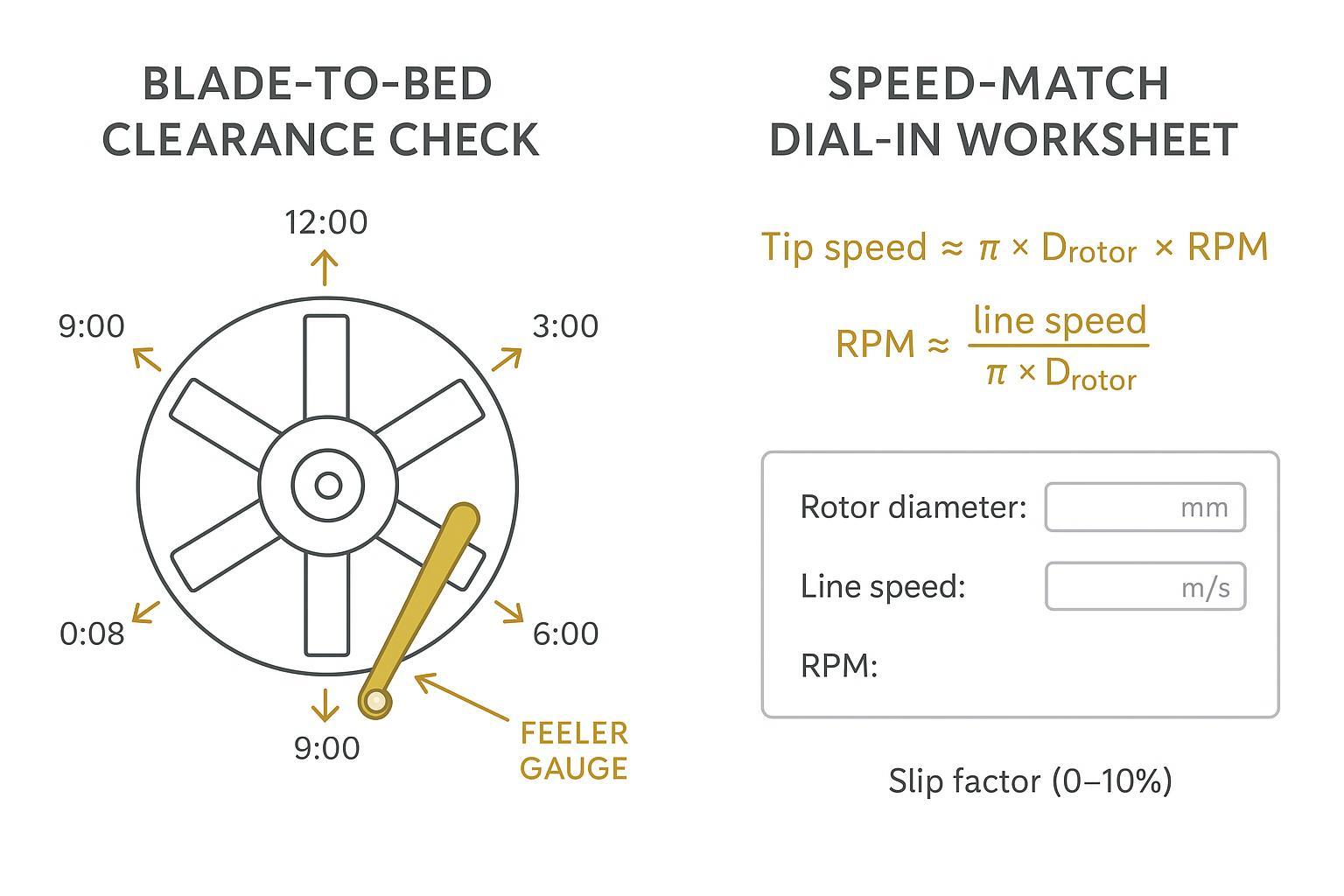
Infographic: Clearance check points and speed‑match worksheet for dial‑in.
Cooling, dewatering, and die hygiene for reducing pelletising fines
Right‑size bath and water temperature
Bath length and temperature set up strand stability long before the cut. A practical way to size the bath is to estimate required cooling time from polymer properties and line speed, then convert to length—a method outlined by Plastics Technology in its guidance on determining water‑bath length for strand pelletising. See the engineering approach in the article “Strand Pelletizing: Follow These Steps to Determine Your Water Bath Length” from Plastics Technology (2013, method still widely used).
For PP/PE, many processors operate between 20–40 °C and adjust based on strand behaviour; warmer baths can help reduce sticking in some copolymers, but avoid drifting above ~45 °C without local trials. Troubleshooting guides such as “The Path to Pellet Perfection” by Plastics Technology (2019) provide useful context for balancing cooling and strand integrity. This tuning contributes directly to pellet dust reduction downstream.
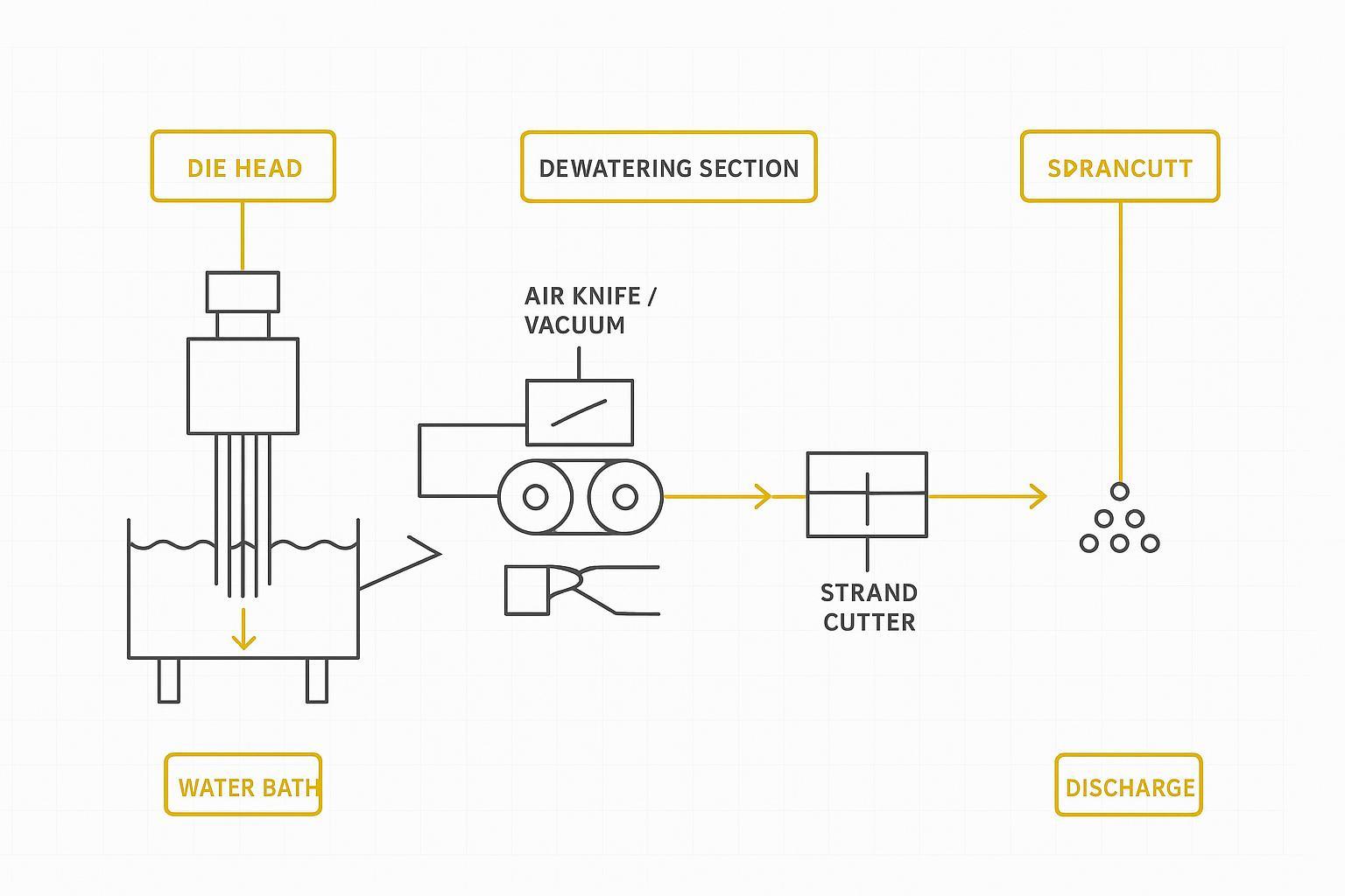
Dewater >95% before cutting
On water‑strand lines, free surface water left on the strand promotes hydroplaning across the bed‑knife, raising fines. As an engineering target, remove >95% of free (surface) water before the strand enters the cutter using an air knife or vacuum slot, followed by nip rollers that establish steady traction. Treat “>95%” as a heuristic starting point (not a published universal standard): what matters is that the strand does not skate at the nip or “float” across the bed knife. Use ISO‑aligned moisture checks downstream to confirm your dewatering decisions are stabilising the process while reducing pelletising fines.
If fines spike suddenly, a quick triage order that usually saves time is:
- Water carry‑over first: check the air‑knife/vacuum performance, strand “shine” (visible wetting), and whether nip rollers are actually gripping or skating.
- Then cutting stability: confirm the blade‑to‑bed clearance is still uniform around the arc (after heat‑soak), and look for any edge micro‑chipping.
- Then speed match: verify tip speed hasn’t drifted (VFD setpoint, belt slip, gearbox issues) and re‑check the slip factor.
- Then upstream hygiene: look for a screen‑pack ΔP jump or die‑face grooves that can trigger tails that later fracture into dust.
This sequence won’t replace your OEM troubleshooting guide, but it helps teams isolate the highest‑leverage causes quickly on wet strand lines.
Maintain die‑face and filtration
Grooves or steps on the die face act like tiny ramps that pull tails; those tails then fracture into dust at the cut. Establish an inspection cadence: quick visual check each shift, magnified inspection weekly, and grind the die face when grooves are visible or tails exceed your trigger. Plastics Technology’s column “Mitigating and Troubleshooting Underwater Pelletizing Issues” (2017) discusses how die‑face flatness and blade condition correlate to tails—even though it focuses on underwater systems, the principle holds for strand.
For a strand-specific troubleshooting view of tails and the role of cutting adjustments, see Plastics Technology’s classic guide “Solve Seven Common Pelletizing Problems” (2012), which highlights tails as a common defect that often responds to cutting set-up changes.
Filtration matters too. Rising ΔP across the screen pack drives melt instability and defect bursts; choose a screen‑changer strategy that fits your regrind contamination level and set ΔP triggers for pre‑emptive changes rather than reacting to quality excursions.
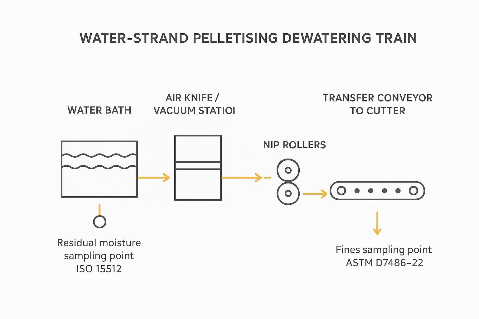
Process flow: Dewatering train with suggested sampling points for residual moisture (ISO 15512) and fines testing (ASTM D7486).
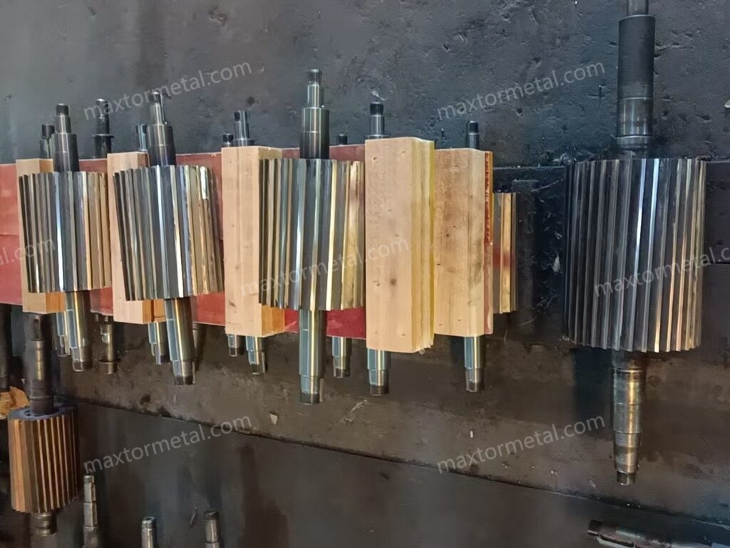
Blade metallurgy and maintenance
Choose wear‑matched materials and coatings
Mixed regrind with variable moisture is unforgiving: hard inclusions and intermittent slip both punish edges. Selecting wear‑matched metallurgy and coatings reduces fines by keeping the edge crisp for longer intervals.
Typical options and bands
- D2 / SKD11 tool steel: good wear at moderate cost; hardness typically HRC 58–61 for strand cutting duties.
- M2 high‑speed steel: higher hot‑hardness and toughness; often HRC 62–64.
- PM/CPM grades (e.g., CPM‑10V class): outstanding abrasive wear resistance; specify hardness per supplier data and verify edge stability under your impact load.
- Carbide‑tipped or inserts: for extreme glass‑filled duty; maximise wear life but require careful set‑up to avoid chipping.
Coatings selection
- TiN: general‑purpose, hard and low‑friction, widely available.
- TiCN: harder with lower friction for abrasive, interrupted cuts.
- CrN: good corrosion resistance; useful with wet operation and certain polymers.
Worked example (supplier‑type specification, illustrative): To stabilise fines on a mixed‑regrind PP/PE line, a plant might specify a strand‑cutter blade in D2 heat‑treated to HRC 60 ±2 with a TiN coating and a ground tolerance of ±0,02 mm on critical dimensions, plus flatness verified against a reference surface. The point of the specification is traceability and repeatability: request material certificates, heat‑treat records, and hardness spot‑checks, and confirm geometry from a sample or drawing for OEM‑level fit.
If you need an example of how such documentation and OEM/ODM fit support can be packaged by a supplier, see MAXTOR METAL’s plastic pelletiser blade page and its industrial blade tolerance guide. This is not a performance guarantee—validate edge stability and life on your own line under your own regrind and moisture conditions.
Small cost‑per‑tonne life illustration
Assume your blade lasts 80 hours before fines exceed the trigger; a D2 HRC 60 ±2 with TiN extends life to 120 hours. If the blade costs £240 and changeover downtime costs £180 per event, previous cost per 80 h = (£240 + £180) / 80 = £5.25/h. New cost per 120 h = (£240 + £180) / 120 = £3.50/h. On a 1 t/h line, that’s a £1.75/h saving, or £1.75/t excluding any yield/fines gains. Treat these numbers as placeholders; plug in your own costs and validated lifetimes.
Regrind and changeover SOPs
Define regrind acceptance in writing rather than by habit. Specify the minimum blade width remaining, the maximum acceptable micro‑chipping at the edge (assessed at ~40× magnification), and post‑grind hardness spot‑checks within the target band. Then, run a disciplined changeover:
- Inspect and clean die‑face and bed‑knife; verify flatness.
- Measure rotor run‑out with a dial indicator; correct if outside plant/OEM limit.
- Set and record clearance at multiple clock positions; rotate by hand to confirm no contact.
- Torque fasteners to spec; heat‑soak, re‑check clearance and run‑out after 15–30 minutes.
- Log fines %, tails and motor current for the first production hour.
Set‑points snapshot (starting values to validate on your line)
| Parámetro | Starting target | Notas |
|---|---|---|
| Blade‑to‑bed clearance | 0.05–0.15 mm | Begin near 0.08 mm for mixed regrind; confirm after heat‑soak; OEM prevails |
| Cutter RPM | line speed / (π × Drotor) | Apply 0–10% slip factor; respect gearbox and edge stability |
| Bath temperature (PP/PE) | 20–40 °C | Adjust on strand behaviour; avoid > ~45 °C without trials |
| Dewatering before cutter | >95% free water removed | Air knife/vacuum + nip; validate locally |
Evidence note: For bath sizing and operating variables, see Plastics Technology bath‑length method (2013) and The Path to Pellet Perfection (2019). For fines and moisture measurement standards, reference ASTM D7486‑22 y ISO 15512.
Conclusión
Recap and cadence
- Mechanics: set uniform clearance (validate across the arc), match tip speed to line speed, and verify alignment/run‑out after heat‑soak.
- Water handling: size and temper the bath, then remove free water aggressively before the cutter to stop hydroplaning while reducing pelletising fines.
- Hygiene & metallurgy: keep the die face flat, filters predictable, and choose blade steels/coatings with documented hardness and tolerances. Regrind and change over to a standard rather than waiting for spikes.
Implementation plan and validation KPIs
- KPIs: fines/dust % by ASTM D7486‑22; residual moisture by ISO 15512; blade life (hours or kg to trigger); downtime per event; cost‑per‑tonne including blades and changeovers.
- Cadence: daily clearance/run‑out spot‑checks; per‑shift dewatering check; weekly die‑face magnified inspection; ΔP‑based screen changes; monthly review of KPI trend lines.
- Validation: change one variable at a time; run for a defined tonnage; document conditions and measurement methods.
Two‑week A/B validation template (copy/paste)
- Rule: change one variable at a time (clearance o RPM slip factor o dewatering setting o screen‑pack change trigger).
- Run length: keep each setting for a fixed time or tonnage (e.g., one shift minimum, then confirm after heat‑soak).
- Log fields (per run): resin/regrind mix, strand count, line speed, rotor diameter, RPM (and slip %), clearance at 3–4 clock positions, bath temperature, dewatering method/settings, screen‑pack ΔP, die‑face condition notes, fines % (ASTM D7486), moisture result (ISO 15512, if used), downtime minutes, and “operator notes” (e.g., visible skating, fuzz, tails).
- Decision trigger: accept a change only if it improves fines % y doesn’t increase downtime or edge damage within the two‑week window.
This small dataset also becomes your internal baseline for future blade‑material and coating trials.
KPI / log sheet (one row per run)
| Campo | Unit / format | When to record | Owner |
|---|---|---|---|
| Resin + regrind mix | % / notes | Each run start | Proceso |
| Strand count | count | Each run start | Operador |
| Line speed | m/min | Each run + after heat‑soak | Operador |
| Rotor diameter | metro | Once (per machine) | Mantenimiento |
| Cutter RPM | rpm | Each run + after heat‑soak | Operador |
| Slip factor | % | Each run | Proceso |
| Clearance readings | mm at 3–4 clock positions | After set‑up + after heat‑soak | Mantenimiento |
| Bath temperature | °C | Cada hora | Operador |
| Dewatering setting | air‑knife / vacuum / nip notes | Each run + after adjustments | Operador |
| Screen‑pack ΔP | bar or kPa | Cada hora | Operador |
| Die‑face condition | short notes / photo ref | Each shift | Mantenimiento |
| Fines / dust | % (ASTM D7486) | Per agreed sample plan | QA |
| Moisture | % (ISO 15512, if used) | Per agreed sample plan | QA |
| Falta del tiempo | minutes | Each event | Supervisor |
| Edge condition | 40× notes (chips / burnish) | Daily during trial | Mantenimiento |
If you want to tighten authority further, you can attach this table as a controlled document (revision number + date + owner) in your plant SOP library.
For custom blade specifications with certificates and OEM/ODM fit, you can request sample validation from MAXTOR METAL.
Autor
Tommy Tang — Senior Sales Engineer, Nanjing METAL Industrial. 12 years in industrial cutting solutions for plastics processing and pelletising operations. Certifications: CSE, CME, Six Sigma Green Belt, PMP.
Referencias y lecturas adicionales
- Plastics Technology — Strand Pelletizing: Water Bath Length Method (2013)
- Plastics Technology — The Path to Pellet Perfection (2019)
- Plastics Technology — Solve Seven Common Pelletizing Problems (2012)
- MAAG/Scheer — S3500 Strand and Pultrusion Pelletizer brochure (PDF)
- Bay Plastics Machinery — Basics of Strand Pelletizing training document (PDF)
- ASTM D7486‑22 — Measurement of Fines and Dust on Plastic Pellets and Granules
- ISO 15512 — Plastics — Determination of water content
- MAXTOR METAL — Industrial blade coatings guide; Industrial blade tolerance guide