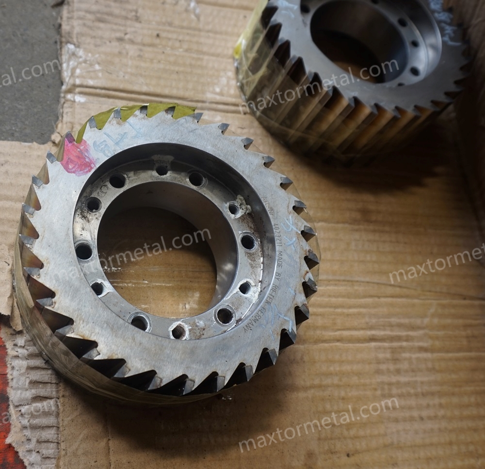
Water‑strand pelletising is a workhorse in UK compounding and recycling. Yet in abrasive, high‑fill and recycled formulations, solid rotary knives wear fast, changeovers drag on, and pellet quality drifts—fines and tails creep up, and operators chase clearances. Inserted blade rotary cutter designs attack the root causes by letting you index or replace edges in situ, rather than removing and regrinding a monolithic rotor.
This guide focuses on UK plants running Maag/Automatik PRIMO/PRIMOplus and Scheer/SGS‑style strand pelletisers. It addresses baseline issues—rapid wear, long changeovers, fines/tails, and pellet variance—and explains how inserted/indexable systems can cut maintenance effort, compress changeovers into controlled, repeatable routines, and stabilise quality when backed by good cooling and alignment practice.
What does the data show? OEM materials on analogous dry‑cut strand pelletisers document significant reductions in disassembly and changeover minutes through tool‑less access and modular heads—e.g., MAAG’s T200 series reports that certain disassembly steps dropped from about 30 minutes to roughly 2 minutes, as described on the manufacturer’s T200 series page, and the PRIMO FC family notes rotor replacement in no more than 30 minutes in a manufacturer news brief on performance innovations. These figures are model‑specific, not a direct head‑to‑head of inserted versus solid knives, so in this guide we treat improvement bands such as 20–50% maintenance reduction, 15–45 minute changeovers, and 2–5× edge life as engineering planning ranges with explicit assumptions and limitations.
How to use this guide: work through the mechanics (how inserted systems differ), then the maintenance cost model (TCO), followed by uptime/quality practices, a retrofit checklist to de‑risk compatibility, and finally a validation plan with KPIs to prove benefits on your line.
Poin-poin penting
- Inserted blade rotary cutter for water‑strand pelletizing can reduce hands‑on maintenance and downtime by enabling in‑situ edge indexing; plan on 20–50% maintenance hour reduction as a conservative engineering range unless site data proves otherwise.
- Expect changeovers for indexing or insert swaps to fit in a 15–45 minute window when scope is defined, tooling is ready, and safe systems of work are followed; analogous OEM claims on related models support the mechanism, not a direct like‑for‑like.
- With appropriate materials, heat treatment and controlled edge radius, indexable inserts can deliver 2–5× usable edge‑life windows in abrasive duty; verify with a matched pre/post trial and documented measurement windows.
- Total cost of ownership shifts because Labour and Lost Production drop when rotors stay in the machine; parts spend moves from rotor regrinds to insert sets—often net‑neutral to lower on a per‑ton basis.
- Stability of pellet quality depends as much on gap/alignment and cooling as on the cutter design; use formal checks for clearance, run‑out and balance, and control fines via ASTM‑aligned methods.
Bagaimana cara kerjanya
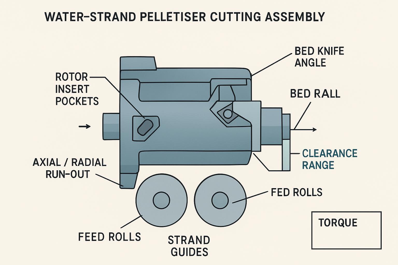
Insert system vs solid knife
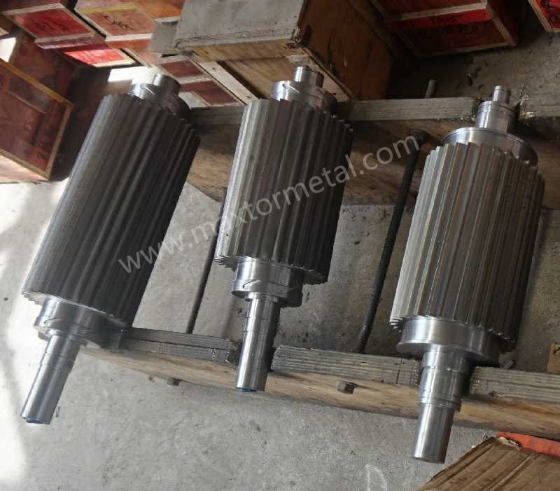
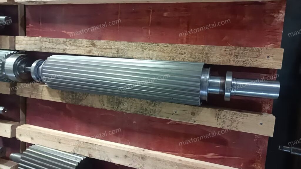
Inserted or indexable systems mount small, hardened cutting inserts in precision‑milled pockets on the rotor. When an edge dulls, you index or replace the insert rather than remove the whole rotor for regrind. Solid knives (monolithic rotors) require rotor removal and regrinding to restore the edge.
| Aspek | Inserted/indexable system | Solid knife/monolithic rotor |
|---|---|---|
| Edge renewal | Index/replace inserts in situ | Remove rotor, regrind, reinstall |
| Typical changeover scope | Loosen insert clamps, index, torque, verify gap | Lockout, disassemble, extract rotor, regrind off‑line, reinstall, re‑align |
| Regrind cycle | Often avoided or deferred | Regular, with cumulative material removal |
| Abrasive duty suitability | Favourable with PM steels/coatings and micro‑hone | Susceptible to chipping and longer regrind downtime |
| Risk points | Pocket wear, clamp torque discipline | Handling damage, regrind variability |
OEM literature for PRIMO/PRIMOplus underscores accessibility and quick tool exchange, and analogous MAAG models document large time savings for disassembly and sub‑assemblies, which explains why inserted systems often halve maintenance when implemented with disciplined SOPs.
Materials and edge geometry
For abrasive, high‑fill and recycled compounds (glass fibre, CaCO3, contaminants), durability comes from the steel grade, heat treatment, surface condition and edge geometry working together:
- Tool or powder‑metallurgy steels with high wear resistance, tempered to verified Rockwell C values appropriate for the duty, reduce micro‑chipping.
- A controlled micro‑hone radius on the cutting edge resists brittle fracture yet keeps the cut crisp.
- Coatings such as TiN/TiCN or hardmetal tipping may be used where compatible with the insert format and bed knife pairing.
When documenting specifications and receiving parts, verify hardness to an accepted method such as ISO 6508‑1 Rockwell testing or the equivalent ASTM E18 and retain batch‑linked records. For background on hardness choices in industrial blades, see the explanatory overview in the ISO entry pages referencing Rockwell hardness testing (ISO 6508‑1) and a practical industrial knife Rockwell hardness guide.
Gap and alignment control
Indexable or not, cut quality depends on mechanical setup:
- Measure cutter‑to‑bed clearance at multiple angular positions; log axial and radial run‑out.
- After insert indexing or replacement, verify rotor balance and permissible run‑out before returning to service. Concepts and tolerances are covered in the ISO 21940 series on rotor balancing (titles and scope).
- Keep strand guides and feed rolls aligned to avoid lateral rub that generates fines and tails. Cooling sufficiency stiffens strands and widens the practical clearance window.
For practical inspection methods and tolerance reporting on industrial blades and assemblies, a helpful overview is available in this inspection and tolerances explainer.
Maintenance cost model
Inserted blade rotary cutter for water‑strand pelletizing changes the TCO shape because you renew edges without rotor extraction. The model has four stacks: Parts, Labour, Lost Production, and Scrap.
Parts and regrind avoided
A solid rotor’s cost pattern is dominated by periodic regrinds and eventual replacement. Inserted systems shift spend to insert sets and pocket upkeep while often reducing or deferring regrind frequency. Two levers drive the economics: edge renewal without rotor extraction cuts handling hours and eliminates regrind transport/queue time; and insert geometry with harder steels maintains edge integrity longer in abrasive duty when paired with the right bed knife hardness.
Labour and downtime
Citable OEM signals on analogous dry‑cut strand pelletisers show how design for access collapses minutes. For example, MAAG’s T200 series reports a reduction from around 30 minutes to approximately 2 minutes for specific disassembly tasks through tool‑less mechanisms, and PRIMO FC reports rotor replacement in no more than 30 minutes. Applied to PRIMO/PRIMOplus and SGS with inserted systems, a conservative planning range for an index or insert swap is 15–45 minutes, assuming defined scope, competent crew, safe isolation, and no seized fasteners.
Quality and waste
Quality losses show up as scrap and rework costs. Measure fines and dust as mass percentage using a recognised method such as ASTM D7486, and track pellet size dispersion as coefficient of variation. Stabilised clearances and fresh edges reduce tails and fines, often improving downstream feeding stability.
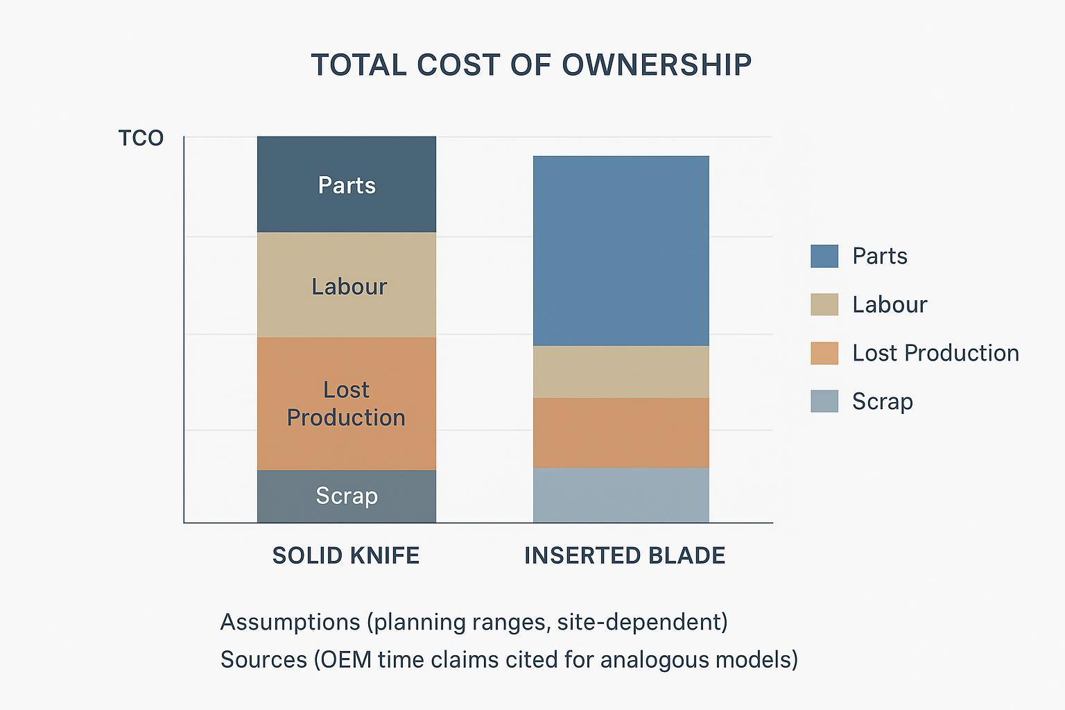
Assumptions note: The chart visualises planning ranges using typical UK labour rates, line‑specific lost‑production valuations, and conservative scrap penalties. Replace with your site data during validation.
Uptime and quality
Changeover time benchmarks
Treat time bands as planning tools, not promises. For indexable systems on PRIMO/PRIMOplus and SGS‑style machines, 15–45 minutes typically covers isolation, indexing or insert swap, torque verification, gap checks, a short run‑in and QC sampling. This aligns directionally with OEM claims on analogous models where tool‑less access compresses sub‑tasks—see MAAG’s T200 series and PRIMO FC time notes for context from the manufacturer pages cited above.
Pellet uniformity, fines, tails
Define and hold a common yardstick. Fines and dust: weigh before/after sieving per ASTM D7486 and report as wt%. Pellet uniformity: capture sample images or caliper data to compute pellet dimension CV; track median and IQR rather than cherry‑picking best runs. Acceptance in abrasive duty: target a sustained reduction in fines percentage versus baseline and a tighter pellet size CV after retrofit and SOP stabilisation.
Cooling and strand condition
Cooling dictates strand stiffness and cut behaviour. Ensure bath length and temperature bring strands below softening before the cut. Practical guidance on estimating bath length and preventing streamers is outlined in Plastics Technology articles such as bath length estimation for strand pelletising dan tips to prevent streamers. Keep trough speed, spray patterns and guide geometry consistent to prevent lateral vibration.
Retrofit checklist
Interface and balance
Before committing to an inserted blade rotary cutter for water‑strand pelletizing on PRIMO/PRIMOplus or SGS‑style lines, verify mounting interface dimensions (shaft, hub, key, axial locating features) and axial stack‑up; rotor envelope (diameter, width), insert pocket geometry and clamp style clearance to guards; and balance grade targets and verification method post‑assembly per ISO 21940 balancing concepts.
Clearance, torque, SOP
Standardise a short, unambiguous SOP. Lockout‑tagout the drive and isolate utilities, then verify zero energy. Index or replace inserts, clean contact faces, apply the specified torque sequence, and record torque values. Set cutter‑to‑bed clearance uniformly, confirm axial/radial run‑out, and perform a brief no‑load rotation check before product runs. Re‑check fastener torque after the first warm cycle, then move to planned intervals.
Documentation and QA
Suppliers should provide batch‑traceable documentation at delivery: material test certificates, heat‑treatment certificates, Rockwell hardness results to ISO 6508‑1 or ASTM E18, and dimensional tolerance reports from an approved inspection method. Serialise rotors and, where practical, insert sets, and maintain regrind/index logs linked to batch IDs.
A neutral example of how a manufacturer frames this is available from LOGAM MAXTOR, which provides batch‑linked QA artefacts and educational resources. For assembling your receiving checklist, see a practical inspection and tolerance explainer and, for hardness background, the industrial knife Rockwell hardness guide. This is offered as context, not as a performance claim.
Trial and validation
KPIs and acceptance
Design a matched pre/post trial on the same product family and throughput. Define windows for maintenance hours per 1,000 tonnes (planned vs unplanned), changeover minutes per event and per 1,000 tonnes, fines percentage by mass and pellet size CV, scrap and restart losses (£/tonne), and any downstream feeder stability incidents. Use medians and IQR across multiple runs. If the inserted solution shows a statistically meaningful reduction in maintenance hours and fines with neutral or lower TCO, approve the change.
Starter spares and policies
For abrasive duty, hold at least one full set of inserts per active edge position plus a contingency reserve for two rapid swaps. Keep critical fasteners, clamps and a torque‑verified tool kit on the line. Define regrind policies for bed knives and any solid companions, and serialise components to track life by batch and station.
Risk controls and safety
Align with UK PUWER duties on work equipment: guard dangerous parts, isolate before maintenance, and ensure competence. See the regulator’s PUWER overview for scope and duties. Embed LOTO in every SOP, specify fastener property classes and torque targets, and verify balance/run‑out after any insert work before returning to production.
Kesimpulan
Inserted/indexable cutters change the economics of water‑strand pelletising by removing rotor extractions from routine maintenance. With disciplined alignment and cooling practice, plants frequently see roughly half the maintenance effort, steadier pellet quality, and safer, shorter changeovers—outcomes you can verify through a simple, standards‑aligned trial.
Next steps: assemble a pilot plan on a single PRIMO/PRIMOplus or SGS line, define KPIs and data capture, run matched trials, and review supplier documentation against a receiving checklist covering MTCs, heat treatment, hardness and tolerances. For neutral QA artefacts and measurement explainers to shape your internal templates, the HSE PUWER guidance and the industrial blade Rockwell hardness guide are practical starting points.
Author and disclosure
Author: Tommy Tang, Senior Sales Engineer, Nanjing METAL Industrial.
Pengalaman: 12 years in industrial blades and pelletising-related cutting applications.
Sertifikasi: CSE, CME, Six Sigma Green Belt, PMP.
Disclosure and update note: This guide is intended for engineering planning and SOP design. Always follow your pelletiser OEM manual, site risk assessments, and UK legal duties (e.g., PUWER) before changing tooling or procedures. Standards and linked sources are periodically reviewed and may change as new revisions are published.