1. 산업용 파쇄기 칼날(Shredder Blades): 엔지니어링 사양 및 소재 선정
본 백서는 산업용 파쇄(shredding), 재활용 및 폐기물 처리 분야에서 Maxtor Metal이 축적해 온 제조 경험을 바탕으로 작성되었습니다.
본 기술 문서는 중공업용 재활용, 고체 폐기물 관리 및 바이오마스 가공 시스템에 적용되는 고성능 파쇄기 칼날(shredder blades)의 엔지니어링 기준, 금상학적(metallurgical) 기준 및 제조 프로토콜을 규정합니다. 본 백서는 예측 가능한 공구 수명, 우수한 절삭날 유지력(edge retention), 치명적 파손에 대한 무결점(zero-defect) 제어를 필요로 하는 구매 담당자, 기계 엔지니어 및 OEM(주문자 상표 부착 생산) 전문가를 위한 핵심 지침서 역할을 합니다.
핵심 요약:
- Maxtor Metal는 AISI D2, DC53, H1.|3, M6V 및 마텐자이트계 스테인리스강 등급의 단축 및 다축 산업용 파쇄기 칼날을 제조하며, 엄격한 감사 대비 품질 및 조달 프로토콜을 준수합니다. 생산되는 모든 칼날은 진공 열처리 및 −196℃ 초저온 안정화 처리를 거치며, Weima, SSI, UNTHA, Vecoplan, Andritz 시스템과의 OEM 호환성을 위해 ±0.01 mm 이내의 정밀 공차로 연삭 가공됩니다.
1 기술 사양 매트릭스
| 매개변수 | 단일 샤프트 슈레더 블레이드 | 다축 파쇄기 칼날 (이축/사축) |
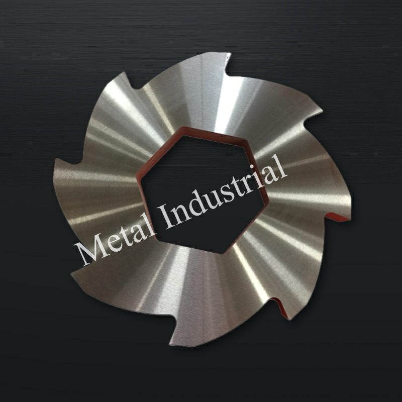
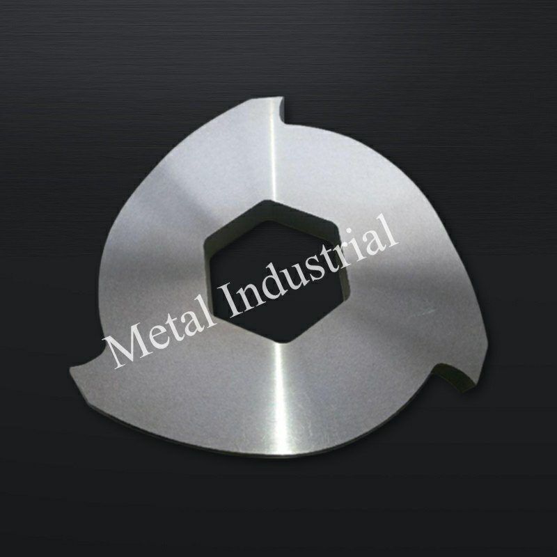
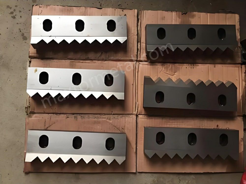
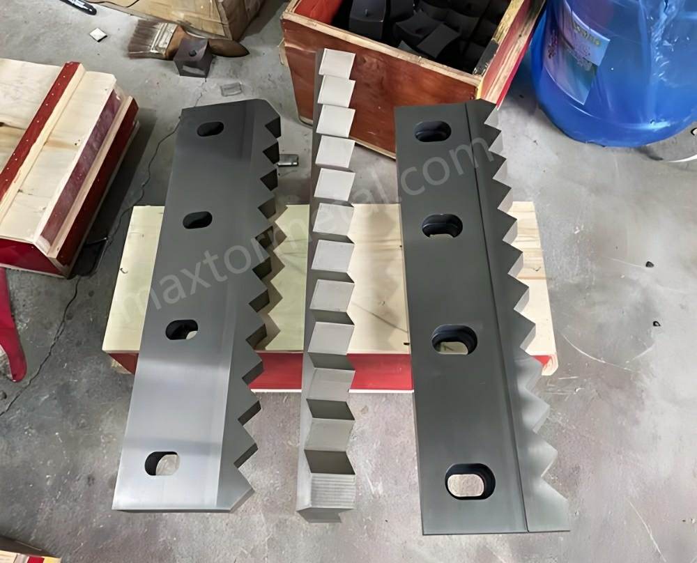
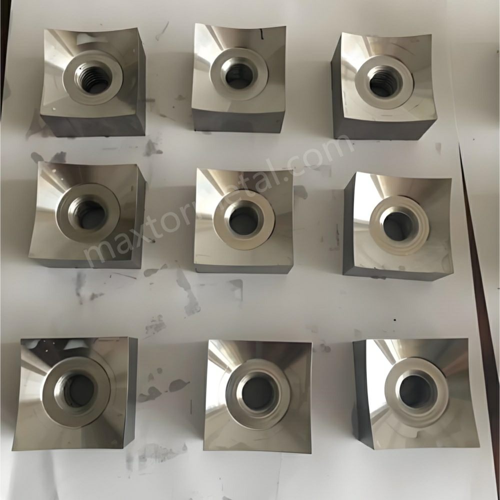
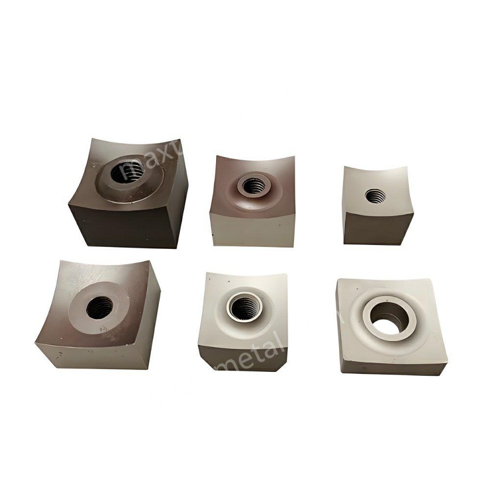
| 주요 칼날 프로파일 | 다각 사각 오목 회전 블록, 고정 칼날. | 다중 클로 인터로킹 디스크 칼날 (3-클로, 5-클로, 8-클로 구성). |
| 절단 메커니즘 | 고정 칼날에 맞선 유압 램 피드를 통한 고속, 고주파 정밀 전단. | 저속, 초고토크 역회전을 통한 체적 그립, 인열 및 고압 파쇄. |
| 핵심 소재 | AISI D2 (1.2379), DC53, AISI 4140 / AISI 1045 베이스 및 브레이징 접합된 Tungsten Carbide 인서트. | AISI H13 (1.2344), AISI A8 Mod, AISI D2, AISI 4140, M6V 바나듐강, DC53, AISI 420, AISI 440C. |
| 경도 범위 | 공구강: 58–60 HRC (진공 열처리). 카바이드 인서트: 인성 강화 매트릭스 기준 89–92 HRA. | 48–54 HRC (인성 중심), 56–60 HRC (내마모 중심), 48–52 HRC (내식성 중심), 58–60 HRC (고탄소 마텐자이트계). |
| 주요 규격 | 중앙 카운터싱크 볼트 홀이 있는 34×34×20 mm, 40×40×20 mm, 60×60×30 mm. | 외경 (OD): 150–600 mm. 두께: 15–60 mm. 보어: 육각, 팔각 또는 인볼류트 스플라인. |
| 치수 공차 | 일반: ISO 2768-mK. 베이스 안착부 및 샤프트 결합면: 엄격한 ±0.02mm. | 두께: ISO 2768-mK. 고정밀 애플리케이션: 단면 평탄도 최대 ±0.01mm 이하. |
| 표면 마감 | 오목 절삭면: Ra< 0.8μm. 장착 시트: Ra< 1.6μm. | 밀링/연삭 단면: Ra< 0.8μm. 코어 작업 프로파일: Ra< 3.2μm. |
| 조립 간극 | 미세 간극 플라이 나이프 설정: 특정 재료 두께에 맞춰 0.1–0.5 mm 조정. | 축방향 오픈 인터로킹 간극: 0.15–0.40 mm 측면 갭 (스페이서는 칼날보다 0.3–0.8 mm 더 넓음). |
| 호환 가능한 OEM | Weima, Vecoplan, Lindner, Herbold 및 이와 동등한 글로벌 단축 시스템. | Weima (사축), SSI, UNTHA, Andritz 중대형 환경 처리 라인. |

2. 파쇄기 칼날 엔지니어링 오버뷰
산업용 입도 감소는 고주파 정밀 전단과 저속 고토크 인열이라는 두 가지 고유한 기계적 전단 공정에 의존합니다. 이러한 작업의 메커니즘을 이해하는 것은 공구 수명과 시스템 효율성을 예측하는 데 필수적입니다.
2 다축 인열 역학
다축 산업용 파쇄기(이축 또는 사축 구성)는 저속이지만 고토크로 회전하는 역회전 샤프트를 통해 작동합니다. 이 공정은 맞물리는 갈고리 모양의 클로 프로파일을 사용하여 크고 밀도가 높은 자재를 절단 챔버 중앙으로 끌어당깁니다.
파쇄 작용은 갈고리 인장 인열, 고압 측면 압착 및 맞물리는 측면 전단의 조합을 사용합니다. 깔끔한 전단보다는 체적 변위와 심각한 구조적 인열에 메커니즘의 초점이 맞춰져 있습니다. 개방형 축방향 간극 시스템(칼날당 0.15mm – 0.4mm 측면 갭)은 독립적인 열팽창을 허용하고 고부하 상태에서의 구조적 변형을 처리합니다.
1 단축 절삭 역학
단축 파쇄 시스템은 더 높은 회전 속도로 작동하며, 유압 램을 사용하여 벌크 자재를 중고속으로 회전하는 로터 쪽으로 밀어 넣습니다. 절삭 메커니즘은 회전하는 사각 인서트(회전 칼날)와 고정 카운터 나이프(고정 칼날) 사이에서 발생하는 정밀한 미세 간극 가위 작용입니다.
재료에 가해지는 일차 응력은 다음과 같이 정의되는 순수 전단 응력입니다.
$$\tau = \frac{F_{\text{절삭}}}{A_{\text{전단}}}$$
지배적인 응력 모드는 전단이며, 단위 전단 면적당 절삭력은 τ = F/A로 정의됩니다. 실제로는 좁은 간극(0.1–0.5 mm)이 전단면에 수직인 압축 응력을 유발하여 가공물의 소성 변형과 깔끔한 파단을 촉진합니다. 회전 인서트의 사각 오목 프로파일은 예리한 양(+)의 경사각을 형성하여 메인 구동축에 필요한 피크 전력을 낮춥니다. 최종 배출 입자 크기는 로터 어셈블리 아래에 위치한 분류 스크린에 의해 엄격하게 제어됩니다.
3 산업용 마모 특성
파쇄기 칼날은 가혹한 트라이볼로지 환경에서 작동하며, 공구 성능 저하는 네 가지 고유한 산업용 마모 패턴을 따릅니다.
- 연삭 마모 (미세 플라우잉): 모래, 스케일, 유리 섬유 또는 광물 먼지와 같은 작고 단단한 입자가 공구강 매트릭스를 가로질러 미끄러지면서 미세한 홈을 파고 날카로운 절삭날을 둥글게 만듭니다. 이로 인해 날이 무뎌지고 전력 소비가 증가하며, 깔끔한 절삭 대신 재료가 뜯겨 나가거나 늘어나는 현상이 발생합니다.
- 충격 피로 (치핑 및 미세 박리): 무거운 금속 이물질이나 파쇄 불가능한 트램프 성분이 장비에 들어가면 절삭날에 높은 국부 접촉력이 가해집니다. 소재의 파괴 인성(K1컵)이 부족하면, 이 접촉 응력으로 인해 즉각적인 미세 치핑이나 치명적인 단면 파손이 발생합니다.
- 응착 마모 및 열 연화: 고밀도 폴리머나 고탄성 엘라스토머를 가공하면 절단 계면에 높은 마찰이 발생합니다. 이 국부적인 열은 국부적인 템퍼 연화를 유발하여 재료 손실을 가속화하고 칼날 표면에 폴리머 부착을 초래할 수 있습니다.
- 입계 화학 부식: 도시 고형 폐기물, 음식물 쓰레기 또는 동물성 조직을 처리하면 강재가 높은 수분, 염화물, 유기산 및 염분(pH < 4)에 노출됩니다. 이러한 반응성 환경은 급격한 공식(pitting) 및 입계 산화를 유발하여 강재 매트릭스에서 크롬을 박탈하고 기계적 마모를 가속화합니다.
3. 산업용 파쇄기 칼날 주요 적용 분야
1 고급 플라스틱 및 폴리머 재생
- 대상 가공 장비: 가변 토크 유압 램을 갖춘 고처리량 단축 파쇄기.
- 투입 원료 구성: 모래나 흙으로 오염된 두꺼운 벽체의 폴리올레핀 파이프, 사출 성형 퍼지(purge), 자동차 범퍼 및 폐농업용 필름.
- 운전 엔지니어링 기준: 유리 섬유 및 광물 필러로 인한 높은 연마 마찰. 플라스틱 필름이 늘어나 로터에 감기는 것을 방지하기 위해 우수한 칼날 유지력(edge retention)이 필요함.
- 권장 사양: 58–60 HRC로 전경화(through-hardened)된 AISI D2 또는 DC53 로터리 인서트. 모래 오염이 심한 경우, 브레이징된 Tungsten Carbide (89–92 HRA) 인서트가 있는 AISI 4140 베이스를 사용하십시오.
2 대용량 전기 케이블 및 전자폐기물(E-Waste) 처리
- 대상 가공 장비: 고정밀, 미세 간극(micro-clearance) 단축 분쇄기 및 파쇄기.
- 투입 원료 구성: 외장형(armor-clad) 구리/알루미늄 전력 케이블, 통신선 및 전자폐기물 조립품.
- 운전 엔지니어링 기준: 과도한 열 발생이나 절연체 번짐(smear) 없이 엘라스토머 재킷에서 구리 가닥을 깨끗하게 분리하기 위해 정밀한 저간극 절단(0.1mm – 0.2mm)이 필요함.
- 권장 사양: 숨겨진 스틸 패스너로 인한 미세 치핑(micro-chipping)을 방지하기 위한 DC53 공구강. 수명 연장을 위해 고정 칼날(stator) 표면에 물리 기상 증착(PVD) Titanium Nitride (TiN) 코팅(>2000HV)을 적용하십시오.
3 중대형 산업용 고형 폐기물 및 유해 폐기물 관리
- 대상 가공 장비: 고토크, 저속 양축(dual-shaft) 또는 4축(quad-shaft) 중산업용 파쇄기.
- 투입 원료 구성: 스틸 드럼, 구조용 자동차 스크랩, 보강된 보관 용기 및 구조용 강판을 포함하는 혼합 유해 폐기물.
- 운전 엔지니어링 기준: 파쇄 불가능한 두꺼운 부품을 만났을 때 커팅 클로(cutting claw)에 가해지는 극심한 충격 하중 및 높은 비틀림 힘.
- 권장 사양: 48–54 HRC로 전경화된 AISI H13 (1.2344) 또는 개량형 AISI A8 공구강. 이 선택은 칼날의 파손을 방지하기 위해 순수한 연마 마모 저항성보다 높은 충격 인성과 구조적 저항성을 우선시합니다. 밀접하게 관련된 유해 물질 응용 분야로는 리튬 이온 배터리 재활용이 있으며, 여기서는 충격 인성 외에도 저속 전단, 제어된 분위기 및 HF 저항성 재료가 요구됩니다 — 당사의 리튬 이온 배터리 파쇄 위험 가이드 를 참조하여 전체 엔지니어링 제어 프레임워크를 확인하십시오.
4 폐차(ELV) 타이어 및 고무 처리
- 대상 가공 장비: 점진적 후크(hook) 설계가 적용된 양축 중형 환경 파쇄기.
- 투입 원료 구성: 두껍고 인장 강도가 높은 스틸 비드 와이어 번들을 포함하는 상용차 타이어 완제품.
- 운전 엔지니어링 기준: 가황 고무 화합물로 인한 심한 연마 마찰과 고탄소 스프링 강선을 절단할 때 발생하는 높은 인장/전단 하중의 가혹한 결합.
- 권장 사양: Special M6V vanadium-rich wear-resistant tool steel or premium DC53 hardened to 56–58 HRC to prevent claw breakage under wire tension. The right hardness target here is a trade-off, not a maximum — pushing HRC too high sacrifices the impact toughness needed to survive bead-wire shock and tramp metal strikes. See our guide on balancing hardness vs. toughness for scrap tire and ELV shredder blades for the full cost-per-ton analysis and a documented failure case.
5 대규모 바이오매스 및 농업용 연료 처리
- 대상 가공 장비: 다중 클로(multi-claw) 구성을 사용하는 고토크 4축 파쇄기 시스템.
- 투입 원료 구성: 고밀도로 압축된 농업용 짚, 작물 줄기, 임업 부산물 및 구조용 패스너를 포함하는 목재 팔레트.
- 운전 엔지니어링 기준: 섬유질 바이오매스 원료는 파쇄 샤프트에 쉽게 감겨 높은 반경 방향 힘과 마찰을 유발합니다. 숨겨진 돌이나 금속 와이어는 갑작스러운 충격 하중을 유발할 수 있습니다.
- 권장 사양: 비용 효율적인 인성이 요구되는 표준 작업을 위해 48–54 HRC로 전경화된 AISI 4140 (1.7225) 구조용 공구강. 연속 RDF(고형폐기물 연료) 처리 라인의 경우 프리미엄 M6V 바나듐강으로 업그레이드하십시오. 이러한 라인에서는 재료 선택만으로는 규격 준수를 보장할 수 없으며, 커터 기하학적 구조, 스크린 개구율(open-area ratio) 및 전단 간극(shear-gap) 제어도 똑같이 결정적인 역할을 합니다. 당사의 가이드인 RDF/SRF 처리 효율을 위한 장조각 불량 방지 엔지니어링 을 참조하여 전체 시스템 수준의 접근 방식을 확인하십시오.
6 유기성 도시 폐기물, 음식물 쓰레기 및 동물 사체 처리(Rendering)
- 대상 가공 장비: 액체 밀봉(liquid-tight) 어레이를 갖춘 양축 유기성 폐기물 파쇄기.
- 투입 원료 구성: 식기류/세라믹이 혼입된 소비 후 음식물 쓰레기, 동물 사체 완제품, 조밀한 뼈 구조 및 렌더링 작업에서 발생하는 발굽.
- 운전 엔지니어링 기준: 조밀한 뼈나 혼입된 식기류로 인한 충격 하중과 결합된 고수분 유기산, 고농도 염분 및 지속적인 부식성 마모에 대한 심각한 노출.
- 권장 사양: 세라믹/식기류가 혼입된 강산성 음식물 쓰레기의 경우, 48–52 HRC로 경화된 AISI 420 마르텐사이트계 스테인리스강을 사용하십시오. 무거운 이물질 금속(tramp metal)이 없는 순수 사체 처리 및 동물 렌더링의 경우, 높은 부식 저항성과 뼈 파쇄 칼날 수명을 위해 58–60 HRC로 경화된 고탄소 AISI 440C 마르텐사이트강을 사용하십시오.
4.주요 파손 문제 및 엔지니어링 솔루션
1 이물질 금속(Tramp Metal)으로 인한 단축 공구 치핑
- 근본 원인 분석: 파쇄 불가능한 강철 부품(예: 경화 볼트, 구조용 브래킷)이 단축 파쇄기에 유입되면, 고경도 회전 칼날(58–60 HRC)과 고정 칼날(stator bed) 사이에 끼이게 됩니다. 이러한 갑작스러운 걸림 현상은 국부적인 응력을 발생시켜 AISI D2 강의 파괴 인성(K1컵)을 초과하게 만들며, 이로 인해 심각한 칼날 이빠짐이나 본체 파손이 발생합니다.
- 엔지니어링 재설계 및 트레이드오프: AISI D2를 DC53 강으로 교체합니다. DC53은 균일하고 미세한 탄화물 구조를 특징으로 하여, 기존 D2에 비해 샤르피 V-노치 충격 에너지를 두 배로 높여줍니다. 엔지니어링 트레이드오프: 재료 비용은 약 25% 증가하지만, 공구 수명과 치명적인 파손에 대한 저항성은 크게 향상됩니다.
2 높은 바이오매스 응력 하에서의 다축 클로 파손
- 근본 원인 분석: 밀도가 높고 섬유질이 많은 바이오매스나 농업용 짚단을 가공할 때, 긴 섬유가 커터 클로의 뿌리 부분에 단단히 감길 수 있습니다. 이러한 감김 현상으로 인해 인접한 칼날 사이에 재료가 끼이게 되며, 이로 인해 높은 굽힘 모멘트와 인장 하중이 발생하여 클로 뿌리 부분이 부러질 수 있습니다.
- 엔지니어링 재설계 및 트레이드오프: 칼날 재질을 고경도 D2 강에서 고인성 AISI H13 (1.2344) 또는 개량형 AISI A8 강으로 변경하고, 48–54 HRC로 열처리합니다. 이를 통해 강철 기질이 내마모성 중심의 탄화물 구조에서 내충격성 마르텐사이트 구조로 전환됩니다. 엔지니어링 트레이드오프: Lowering the hardness reduces abrasive wear resistance, requiring more frequent edge sharpening to maintain throughput.
4.3 Inner Drive Bore Cracking via Wire EDM Residual Stress
- 근본 원인 분석: Precise internal driven profiles (such as hex or octagonal shapes) are commonly finished using Wire Electrical Discharge Machining (EDM) after heat treatment. The high temperatures of the EDM process melt and re-solidify the steel surface, creating a microscale brittle “white layer” filled with residual tensile stresses. Under high torque, these internal corners act as stress concentrators, initiating cracks that propagate outward and split the blade.
- 엔지니어링 재설계 및 트레이드오프: Implement an immediate post-EDM low-temperature stress-relief temper at 180℃ – 200℃ for 4 hours to relieve the residual tensile stresses. Alternatively, upgrade the material to DC53, which can absorb these stresses without requiring special multi-step tempering steps.
4.4 Axial Expansion and Seizure of Multi-Shaft Assemblies
- 근본 원인 분석: Processing dense materials over long, continuous runs generates high friction, heating the shredder blades up to 80℃ – 120℃. If the thermal expansion of the blades exceeds the original engineered axial clearances, the side faces of the interlocking cutters will grind against each other, leading to frictional lockup, shaft deflection, and gear drive overload.
- 엔지니어링 재설계 및 트레이드오프: Increase the thickness of the spacer collars relative to the blades, setting a single-side clearance gap of 0.15 mm to 0.40 mm (making the spacer 0.3 mm to 0.8 mm wider than the corresponding blade). Additionally, apply a -196℃ cryogenic treatment during heat treatment to eliminate retained austenite, ensuring high dimensional stability over a wide temperature range. 엔지니어링 트레이드오프: Larger clearance gaps can allow thin sheet materials to pass through without being fully shredded. For the full tolerance-chain analysis behind these clearance targets — including GD&T flatness/parallelism/perpendicularity callouts, spacer selective-fit binning, and post-assembly TIR acceptance gates — see our Multi-shaft Blade Tolerance Stacking guide.
4.5 Rapid Chemical Corrosion and Edge Softening in Biomass Processing
- 근본 원인 분석: Processing organic food waste or animal carcasses releases high-moisture organic acids and chlorides (pH < 4). Standard cold-work tool steels like AISI D2 or DC53 lack sufficient free chromium, causing them to form iron oxides and pit rapidly under these conditions. This corrosion compromises the steel matrix, accelerating mechanical wear and causing the cutting edge to dull quickly.
- 엔지니어링 재설계 및 트레이드오프: Upgrade the cutter material to AISI 420 martensitic stainless steel (hardened to 48–52 HRC) or AISI 440C high-carbon stainless steel (hardened to 58–60 HRC), depending on the amount of mixed tramp metal present. 엔지니어링 트레이드오프: Stainless tool steels are more difficult to precision-grind, increasing manufacturing costs and lead times.
4.6 Single-Shaft Rotary Blade Seating Loosening
- 근본 원인 분석: High-frequency cutting forces apply cyclic, pulsing loads to single-shaft rotary inserts. If the dimensional tolerance between the insert’s bottom seating face and the rotor’s machined pocket exceeds 0.05 mm, the insert can shift micro-axially during operation. This movement puts high cyclic shear stresses on the central fastening bolt, leading to bolt fatigue and eventual failure.
- 엔지니어링 재설계 및 트레이드오프: Tighten the dimensional tolerances on the blade’s bottom seating and locator faces to a strict ±0.02mm via precision grinding. 엔지니어링 트레이드오프: Requires high-precision CNC grinding fixtures, which increases tool manufacturing costs.
4.7 Severe Abrasive Edge Rounding from Glass-Fiber Reinforced Polymers
- 근본 원인 분석: Glass fibers (GF) used in engineering plastics act as high-hardness abrasives during shredding. When these fibers slide across standard tool steel, they cause micro-ploughing that rapidly rounds the sharp cutting edge. Once rounded, the blade can no longer cut the plastic cleanly, increasing power consumption and generating friction that melts the polymer.
- 엔지니어링 재설계 및 트레이드오프: Use composite blades featuring an AISI 1045 or 4140 structural steel body with brazed Tungsten Carbide (WC-Co) inserts at the cutting edges. The carbide inserts provide high hardness (89–92 HRA) to resist fiber abrasion, while the steel body maintains structural toughness. 엔지니어링 트레이드오프: High-vibration environments or tramp metal impacts can cause the brittle carbide inserts to crack or debond from the steel base.
4.8 Premature Corner Chipping on Square Concave Inserts
- 근본 원인 분석: The four corner tips of single-shaft square concave inserts concentrate stress during operation. If the concave radius is ground too deep, the resulting edge geometry becomes too fragile, making the corners prone to micro-chipping under standard impact loads.
- 엔지니어링 재설계 및 트레이드오프: Optimize the grinding geometry by reducing the concave depth and introducing a small, controlled 0.1 mm chamfer or hone to the cutting edge. This reinforces the corner geometry with minimal impact on overall cutting sharpness.
4.9 Frictional Galling on Multi-Shaft Interlocking Faces
- 근본 원인 분석: When shredding ductile materials like aluminum alloys or soft polymers, high lateral pressures can force the material into the side gaps between interlocking blades. This trapped material undergoes high friction and pressure, leading to localized cold-welding and material transfer (galling) onto the blade faces, which increases torque and friction.
- 엔지니어링 재설계 및 트레이드오프: Precision-grind the blade side faces to a smooth surface finish of Ra< 0.8μm to reduce friction. For highly ductile applications, add shallow radial escape grooves across the blade faces to help eject trapped particles. Introduce radial scraper fins onto the side profiles of the blades to help eject fine particles from the gap.
4.10 Thermal Cracking (Heat Checking) from Continuous Friction
- 근본 원인 분석: Shredding highly elastic materials can generate high continuous friction, creating localized thermal gradients across the blade edge. The resulting cyclical thermal expansion and contraction can cause microscale thermal cracks (heat checking) perpendicular to the cutting edge, which can lead to larger structural failures.
- 엔지니어링 재설계 및 트레이드오프: Select tool steels with high thermal conductivity and temper resistance, such as AISI H13. Ensure the shredding system uses an automated reverse cycle or external cooling to manage operating temperatures.
5.재질 엔지니어링 가이드
Selecting the proper steel alloy requires balancing three conflicting properties: wear resistance, impact toughness, and manufacturability (grindability).
5.1 Metallurgical Matrix Comparison
The following alloy comparison reflects Maxtor Metal’s qualified material library for shredder blade production.
| International Alloy Standard | Primary Microstructural Carbides | Charpy V-Notch Impact Energy (Toughness) | 연마 마모 저항성 | Machining & Grindability Index |
| AISI D2 / DIN 1.2379 / SKD11 | Large, banded eutectic chromium carbides (Cr7C3). | Low (20 – 25 J/cm2). | High. | Difficult; high wheel wear. |
| DC53 (Premium Cold-Work) | Fine, evenly dispersed secondary alloy carbides. | Very High (28 – 45 J/cm2). | Excellent. | Fair; superior to D2. |
| AISI H13 / DIN 1.2344 | Fine vanadium/molybdenum carbides. | Exceptional (50 – 80 J/cm2). | Moderate. | Good; high machinability. |
| AISI A8 Mod (Toughness Tool) | Balanced chromium/molybdenum matrix. | Excellent (80 – 100J/cm2). | Medium-High. | Fair. |
| M6V (High-Vanadium Tool) | Ultra-hard vanadium carbides (VC, 2800HV). | Moderate-High (35 – 40J/cm2). | Superior long-life. | Difficult; requires specialized wheels. |
| AISI 4140 / DIN 1.7225 | Homogeneous tempered martensite (no primary carbides). | High structural ductility. | Low; requires base support. | Excellent; low manufacturing cost. |
| AISI 420 / DIN 1.4021 | Dispersed chromium carbides in a stainless matrix. | High (60 – 80J/cm2). | Medium. | Good. |
| AISI 440C / DIN 1.4125 | High-density primary chromium carbides. | Low-Moderate (15 – 22J/cm2). | High. | Difficult. |
| Tungsten Carbide (WC-Co) | Pure sintered Tungsten Carbide grains. | Brittle; low impact threshold. | Maximum Industrial. | Requires diamond grinding. |
Impact energy values are measured at target working hardness after vacuum hardening and triple tempering. Values at annealed state are significantly higher and are not representative of service conditions.
5.2 Advanced Metallurgical Selection Guidelines
5.2.1 AISI D2 vs. DC53
Traditional D2 steel contains large, non-uniform chromium carbides that form during solidification. These carbides act as stress concentration sites where micro-cracks can easily initiate under heavy shock loads. In contrast, DC53 modifies the chemical composition to eliminate these large carbide bands, resulting in a fine, uniform carbide distribution. This microstructural improvement doubles the material’s impact toughness while maintaining equivalent or superior wear resistance at high hardness levels (58–60 HRC).
5.2.2 Specialized Environmental Alloys (M6V, 420, 440C)
- M6V: Contains high amounts of vanadium, which forms ultra-hard vanadium carbides throughout the matrix. This alloy is ideal for high-volume, continuous processing lines like RDF generation, where long tool life is critical to reducing downtime.
- AISI 420 & 440C: These martensitic stainless steels are selected for highly corrosive applications. AISI 420 provides the impact toughness needed to handle mixed municipal waste containing occasional hard impurities. AISI 440C features higher carbon and chromium content, providing excellent edge retention and wear resistance for pure organic processing, such as animal carcass rendering. 440C’s corrosion resistance also extends to HF-exposed environments such as lithium-ion battery shredding; for material mitigations and wetted-component guidance in that setting, see 리튬 이온 배터리 파쇄 위험성: 저속 전단 제어 기술, 불활성 분위기 설계 및 HF 가스 처리 대책.

6. 파쇄기 칼날 열처리 공정 및 경도 밸런스
Industrial shredder blades require precise heat treatment to achieve the proper balance of hardness and toughness. Incorrect tempering or incomplete phase transformation can lead to premature tool failure.
6.1 Vacuum Austenitizing & Controlled Quenching
Blades are heat-treated in a high-vacuum furnace (10-4mbar) to prevent surface decarburization and oxidation. For premium tool steels like D2 and DC53, the material is preheated in stages to minimize thermal distortion before being brought to its final austenitizing temperature (1020℃ – 1040℃). Once uniform carbon dissolution is reached, the parts undergo a high-pressure gas nitrogen quench (6 – 10bar) to quickly transform the austenite matrix into hard martensite.
6.2 Deep Cryogenic Transformation Process
Following the quench, the steel matrix can retain up to 5% to 15% unstable retained austenite. To ensure long-term dimensional stability and prevent distortion or cracking under heavy structural loads, blades undergo a deep cryogenic treatment:
- The temperature is lowered at a controlled rate (1℃/min) down to -196℃ using liquid nitrogen.
- The blades are held at -196℃ for 12 to 24 hours.
This process forces the complete transformation of retained austenite into martensite and promotes the precipitation of fine η-carbides, improving both wear resistance and structural stability.
6.3 Precision Tempering Strategies
Tempering modifies the hard, brittle martensitic structure into a tougher, more resilient tempered martensite.
- High-Temperature Tempering (Secondary Hardening Window): For D2 and DC53 blades used in high-wear applications, triple tempering is performed at 520℃ – 540℃. This triggers secondary carbide precipitation, maximizing wear resistance while maintaining a stable hardness of 58–60 HRC.
- Low-Temperature Tempering (Toughness Window):
- For shredder blades utilizing AISI D2, tempering is conducted at 180℃ – 200℃ to relieve quenching stresses and achieve peak impact toughness while maintaining a high working hardness of 58–61 HRC. To prevent micro-cracking during subsequent Wire EDM for internal shaft bores, a mandatory post-EDM stress-relief temper at 180℃ – 200℃ for 4 hours must be enforced.
- For multi-shaft claw configurations subjected to severe operational shock loads, AISI H13 items must undergo high-temperature tempering cycles within 550℃ – 580℃. This drives complete secondary transformation and matrix stress-relief, establishing a stable tempered martensite structure that delivers its peak Charpy impact energy while targeting a hardness of 48–54 HRC.
7. 칼날 기하학 구조(Geometry) 및 절단 날 제어 기술
The geometric design of a shredder blade determines its cutting efficiency, material throughput, and structural durability.
7.1 Single-Shaft Insert Architecture
Single-shaft rotary knives are typically designed as multi-angle square concave inserts. The concave face creates an aggressive, positive rake angle (α = +10°to +15°) that helps pull material into the cutting zone, lowering the required drive motor power.
The center of the insert features a precision-machined countersunk hole designed to accept high-tensile socket head cap screws, securing the blade tightly into its rotor pocket. This pocket provides multi-surface support to absorb high radial and axial cutting forces.
7.2 Multi-Shaft Claw Profiles and Bore Mechanics
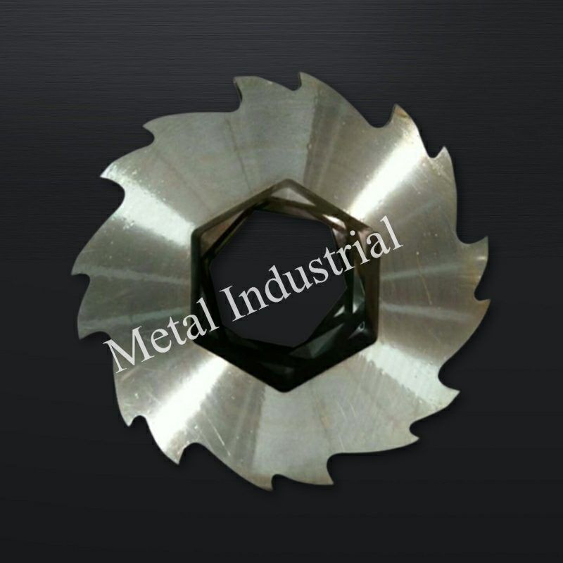
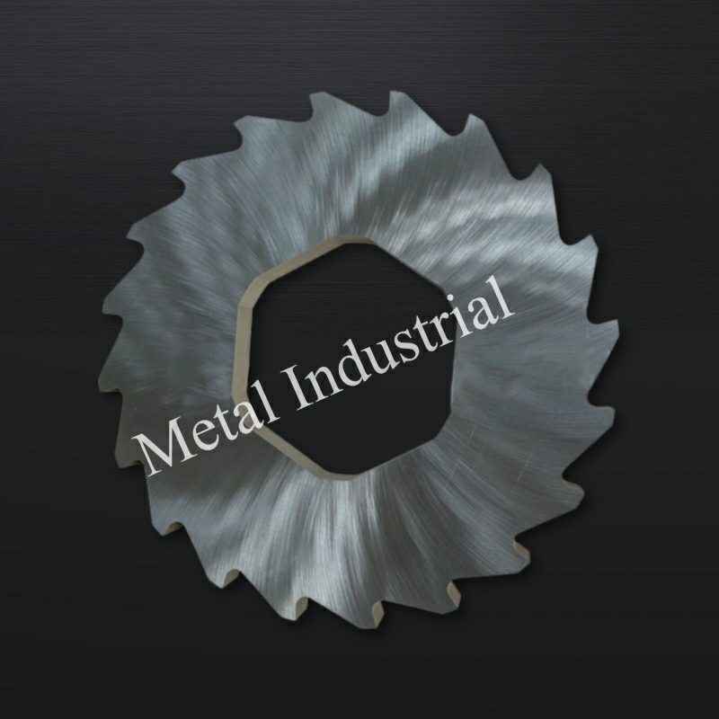
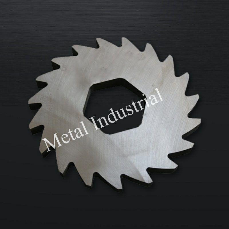
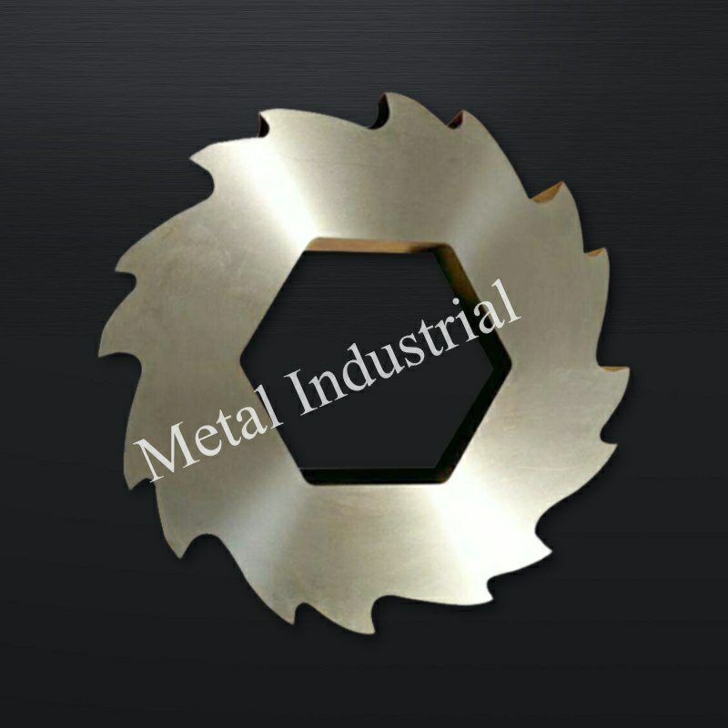
Multi-shaft blades are styled as disk cutters featuring a variable number of cutting claws (typically 3-claw, 5-claw, or 8-claw configurations).
- 3-Claw Profile: Features deep, aggressive hooks with a tall profile, making it ideal for grabbing and tearing bulky, hollow items like plastic drums or car body shells.
- 8-Claw Profile: Features shorter, closely spaced claws designed for high-density, uniform sizing applications, such as tire shredding or fine biomass processing.
The design of the internal drive bore is critical for delivering high torque from the main drive shaft:
- Hexagonal / Octagonal Bores: Provide positive mechanical engagement but feature sharp internal corners that act as stress concentrators.
- Involute Spline Bores: Feature a series of matching internal teeth that distribute torsional loads evenly across the entire circumference. This design significantly reduces localized stress concentration, making it ideal for heavy-duty recycling operations.
8. 파쇄기 칼날 제조 공정 및 품질 검사(QC) 체계
To ensure reliable performance in demanding recycling environments, shredder blades must follow strict, quality-controlled manufacturing stages.
8.1 Advanced Manufacturing Workflow
Maxtor Metal’s standard manufacturing sequence for industrial shredder blades follows eight controlled stages:
- Material Sourcing & Forging: Use clean, vacuum-degassed tool steel ingots. Perform 3D multi-directional forging to ensure uniform grain structure and break up coarse carbide bands.
- Spheroidized Annealing: Heat-treat to produce a uniform distribution of granular carbides within a soft ferrite matrix, ensuring consistent machinability and dimensional stability.
- CNC Rough Machining: Mill the core blade profiles, drill countersunk holes, and rough-turn the outer diameter, leaving a uniform 0.3mm – 0.5mm grinding allowance across all critical faces.
- Vacuum Heat Treatment & Cryogenic Stabilization: Execute the complete vacuum hardening, liquid nitrogen deep freeze, and triple tempering sequence to fix the material’s microstructural properties.
- Precision Super-Grinding: Use specialized CNC surface grinders equipped with vitrified CBN (Cubic Boron Nitride) or diamond wheels to finish the cutting edges to a smooth surface finish of Ra< 0.8μm.
- Wire EDM Profiling (For Complex Bores): Use high-precision wire EDM to cut internal hexagonal or spline bores into the hardened blade body.
- Low-Temperature Stress-Relief Tempering: Immediately temper the parts at 180℃ – 200℃ for a minimum of 4 hours to eliminate residual tensile stresses and the brittle EDM “white layer”.
- Final Quality Control Inspection: Validate all dimensions using automated Coordinate Measuring Machines (CMM).
8.2 Metrology Protocols & Inspection Tolerances
Every finished blade must pass three quality control checks before release:
- End-Face Flatness Verification: Measured using an optical flat or high-precision digital indicator across the entire blade diameter. For high-precision applications, flatness variation must not exceed ±0.01mm.
- Dual-Face Parallelism Testing: The thickness variation between opposing parallel faces is verified at four symmetric points. Total thickness deviation must remain within ±0.05mm to ensure uniform seating when blades are stacked together on a multi-shaft assembly.

9. 고객 도입 성공 사례 (Case Studies)
9.1 Case Study 1: Preventing Cracking in Industrial Silver Recycling
The following data comes from Maxtor Metal’s project support for a precious metals reclamation operator; the customer name has been anonymized.
- Industrial Operator Profile: A high-volume precious metals reclamation plant processing dense, high-purity industrial silver scrap.
- Original Equipment Configuration: Multi-shaft heavy shredder using standard AISI D2 steel blades through-hardened to 60 HRC. Internal drive engagement was handled via a standard wire EDM-cut internal hexagonal bore.
- Operational Failure Analysis: The original D2 blades frequently cracked and split from the sharp corners of the internal hex bore outward during early operation. Investigation revealed that the high torque required to process dense silver scrap amplified the residual tensile stresses left behind by the wire EDM process. The localized micro-cracking was heavily aggravated by the uncontrolled tensile stress fields generated during the legacy vendor’s post-EDM wire cutting, which omitted the critical stress-relief tempering protocol required to eliminate the brittle recast white layer. The large, brittle carbide structures typical of standard D2 steel could not absorb these combined loads, leading to rapid crack propagation and failure.
Evaluation of Engineering Solutions
Solution A: Upgrade to Material DC53
- Engineering Approach: Replace AISI D2 steel with premium DC53 cold-work tool steel while maintaining standard, high-efficiency manufacturing methods.
- Result Matrix: The fine, uniform carbide structure of DC53 doubled the material’s impact energy compared to D2. This increased toughness allowed the steel matrix to naturally absorb the residual stresses from the EDM process and handle the high torque loads without cracking. The blades maintained a high surface hardness of 58–60 HRC, preserving full wear life while shortening manufacturing lead times.
Solution B: Modify Manufacturing via a Four-Step Process
- Engineering Approach: Maintain the original AISI D2 material but completely restructure the manufacturing sequence to isolate and relieve internal stresses:
- Vacuum-harden the blank to a lower, tougher hardness level of 52 HRC.
- Rough-grind both faces, leaving a 0.1mm – 0.2mm machining allowance.
- Wire-EDM cut the internal hexagonal bore profile.
- Perform a long, low-temperature stress-relief temper at 180℃ – 200℃ to relieve internal tensile stresses before a final finish grind.
- Result Matrix: This process successfully prevented internal bore cracking and achieved a precise flatness tolerance of ±0.01mm. However, lowering the hardness to 52 HRC reduced the blades’ wear life by roughly 35%. This approach also significantly increased manufacturing costs, required more complex processing steps, and extended production lead times.
- Final Implementation Decision: The operator chose Solution A. Upgrading to DC53 eliminated the cracking failures, maintained optimal edge wear life, simplified manufacturing, and reduced overall tool production times.
9.2 Case Study 2: Extending Tool Life in Corrosive Organic Waste Processing
The following data comes from Maxtor Metal’s project support for a municipal solid waste processing facility; the customer name has been anonymized.
- Industrial Operator Profile: A municipal solid waste facility operating continuous organic waste and animal rendering lines.
- Original Equipment Configuration: Heavy-duty dual-shaft shredder fitted with standard AISI D2 tool steel multi-claw blades.
- Operational Failure Analysis: The original D2 blades showed severe surface rust and pitting corrosion within hours of processing acidic organic waste (pH < 4.5). This chemical corrosion quickly dulled the cutting edges, causing fibrous materials to wrap around the shafts and clog the machine. The resulting friction led to high operating temperatures, motor overloads, and frequent unscheduled maintenance shutdowns.
- Implemented Engineering Redesign: The D2 blades were replaced with high-carbon martensitic stainless steel (AISI 440C), vacuum-hardened and low-temperature tempered to a stable 59 HRC. The side clearance gaps were also opened to 0.25 mm using wider, corrosion-resistant spacers to handle thermal expansion.
- Quantified Performance Improvement: The upgraded AISI 440C stainless blades resisted organic acid pitting, maintaining a clean cutting edge over long runs. Continuous operating life between sharpening intervals increased from 72 hours to 300 – 580 hours depending on waste stream acidity and throughput rate. Frictional heat generation was significantly reduced, eliminating thermal clogging and lowering overall motor power consumption by 14%.
10. 자주 묻는 질문 (FAQ)
혼합 도시 고형 폐기물(MSW) 파쇄 시 AISI D2 공구강 칼날이 자주 치핑(날 깨짐)되거나 파손되는 이유는 무엇입니까?
AISI D2 강재는 응고 과정에서 형성되는 크고 불균일한 크롬 탄화물을 함유하고 있습니다. 이 탄화물 밴드 조직은 취성이 강해 내부 응력 집중원으로 작용합니다. 파쇄기가 파쇄 불가능한 금속 이물질이나 무거운 돌과 충돌할 때, 급격한 충격 하중이 D2 매트릭스의 파괴 인성을 초과하게 되면서 미세 치핑이나 칼날 본체의 심각한 균열(크랙)을 유발합니다.
Q2: How does upgrading to DC53 help prevent shredder blades from cracking?
A2: DC53 reduces the large chromium carbide bands typical of D2, replacing them with a fine, uniform carbide distribution. Based on Maxtor Metal’s material qualification testing, this microstructural adjustment approximately doubles the Charpy V-notch impact energy compared to standard D2 at equivalent working hardness (58–60 HRC), allowing the blade to better absorb sudden impacts and high torque without fracturing.
Q3: What is the optimal side clearance gap for multi-shaft shredder blades, and why is it necessary?
A3: Based on Maxtor Metal’s multi-shaft assembly specifications, the standard single-side clearance gap ranges from 0.15 mm to 0.40 mm, achieved by making the spacer collar 0.3 mm to 0.8 mm wider than the blade thickness. This built-in clearance accommodates thickness tolerances (ISO 2768-mK) and allows the blades to expand freely as friction heats them up during operation, preventing axial binding and seizure.
Q4: When should Tungsten Carbide inserts be used instead of solid tool steel for single-shaft shredders?
A4: Tungsten Carbide inserts are ideal for high-abrasion applications with low risk of heavy impact, such as shredding agricultural film contaminated with sand or processing glass-fiber reinforced engineering plastics. The carbide tips provide high hardness (89–92 HRA) to resist abrasive wear, while a tough steel base like AISI 4140 provides structural support.
Q5: Why is deep cryogenic treatment (-196℃) recommended for heavy-duty shredder blades?
A5: Cryogenic treatment forces unstable retained austenite to transform completely into stable martensite. In Maxtor Metal’s heat treatment protocol, blades are held at −196℃ for 12 to 24 hours following quench, eliminating residual microstructural stresses that could cause warping or distortion in service, and promoting the precipitation of fine secondary carbides that improve overall wear resistance.
Q6: What causes inner drive bores (hex or octagonal) to split open, and how can this be fixed?
A6: Finishing internal drive bores with wire EDM creates a thin, brittle “white layer” on the steel surface that contains high residual tensile stresses. The sharp corners of hexagonal or octagonal bores also naturally concentrate stress. Under heavy torque, cracks can easily initiate at these corners and propagate outward. This can be prevented by applying a post-EDM stress-relief temper at 180℃ – 200℃ or by upgrading the blade material to high-toughness DC53.
Q7: Which blade material is best for processing corrosive organic food waste?
A7: For organic waste containing high moisture and acids, AISI 420 or AISI 440C martensitic stainless steels are recommended. AISI 420 provides good impact toughness for mixed waste streams, while AISI 440C offers higher hardness (58–60 HRC) and excellent edge retention for high-volume rendering applications, such as carcass processing.
Q8: What surface finish is required for single-shaft rotary blade faces?
A8: Per Maxtor Metal’s grinding and inspection standards, the concave cutting face must be precision-ground to Ra < 0.8 μm to maintain a sharp, low-friction cutting edge, while the flat mounting seats require Ra < 1.6 μm to ensure rigid, secure seating in the rotor pocket.
Q9: Why are standard tool steels ineffective for animal rendering and carcass processing?
A9: Animal fluids contain high concentrations of organic acids and salts that cause standard tool steels like D2 or DC53 to rust and pit rapidly. This corrosive wear breaks down the steel matrix and quickly dulls the cutting edge, leading to material wrapping, friction, and eventual machine overload. Martensitic stainless steels like AISI 440C are required to withstand these conditions.
단축 파쇄기의 스테이터 나이프(고정날)에 PVD TiN(질화티타늄) 코팅을 적용하는 목적은 무엇입니까?
A10: A Titanium Nitride (TiN) coating increases surface hardness to over 2000 HV on the primary shearing faces. This coating acts as a barrier against abrasive wear, making it highly effective for precision applications like electrical cable recycling, where maintaining a clean, sharp edge is critical to preventing insulation smearing.
다축 파쇄기 칼날의 3-클로(claw) 프로파일과 8-클로 프로파일은 적용 용도면에서 어떻게 다릅니까?
A11: A 3-claw profile features tall, aggressive hooks designed to grab and rip bulky, hollow materials like plastic drums, tires, or car scrap. An 8-claw profile features shorter, more frequent hooks that provide less aggressive tearing but deliver higher, more uniform sizing, making it ideal for processing loose biomass or shredded rubber.
Q12: Why are dimensional tolerances for single-shaft blade bases restricted to ±0.02mm?
A12: Single-shaft shredders operate with a high-frequency, pulsing cutting action. Maxtor Metal enforces a strict ±0.02 mm tolerance on blade base seating and locator faces — verified via precision CNC grinding — to ensure a rigid fit within the rotor pocket and prevent the micro-movements that cause fatigue failure of the primary fastening bolts.
Q13: What engineering trade-offs occur when lowering blade hardness to improve toughness?
A13: Lowering a blade’s hardness (for example, tempering D2 steel down to 52 HRC) increases its impact toughness and resistance to cracking. However, this reduces its abrasive wear resistance, meaning the cutting edges will dull faster and require more frequent sharpening or replacement, which increases operational downtime.
Q14: What is the benefit of an involute spline bore over a standard hexagonal bore for multi-shaft drives?
A14: A hexagonal bore concentrates torsional stresses at its six sharp corners, which can lead to fatigue cracks over time. An involute spline bore uses a series of curved teeth to distribute driving torque evenly across the entire circumference of the shaft, significantly lowering localized stress and extending blade life under heavy loads.
Q15: How can you identify if a blade failure was caused by abrasive wear versus impact fatigue?
A15: Abrasive wear shows up as smooth micro-grooves, scratches, and a gradual rounding of the cutting edge over time. Impact fatigue causes sudden micro-chipping, spalling, or large, jagged cracks across the blade body, typically triggered by encountering an uncrushable object.
엔지니어링 최종 행동 촉구
귀하의 파쇄 시스템 처리량(Throughput)을 최적화하십시오
Does your production line experience frequent downtime due to blade chipping, corner cracking, or rapid wear? Shifting from generic replacement parts to precision-engineered shredder blades can stabilize your processing costs and improve system reliability.
Maxtor Metal’s engineering team can review your system drawings and material requirements to develop customized solutions:
- Custom Alloy Matching: We select and treat materials (including DC53, M6V, and AISI 440C) based on your specific waste stream dynamics.
- 정밀 제조: All parts are finished with advanced vacuum heat treatments, cryogenic stabilization, and precision CNC grinding down to ±0.01mm tolerances.
- Direct RFQ Support: Submit your CAD files (.STEP, .DWG) or OEM part numbers today for a detailed technical review and production quote.
Contact our engineering consulting office directly to speak with an industrial knife specialist.
파쇄 블레이드 표시하다:


비디오:
관련 블로그:
-
이중 샤프트 파쇄기의 종합 분석
-
단일 샤프트 분쇄기에 대한 종합 가이드: 유형, 작업 공정, 구성 요소, 유지 관리 및 블레이드
-
분쇄기 블레이드: 분류, 재료 선택, 서비스 수명 및 설계 기술 분석
더 많은 블로그…


 English