

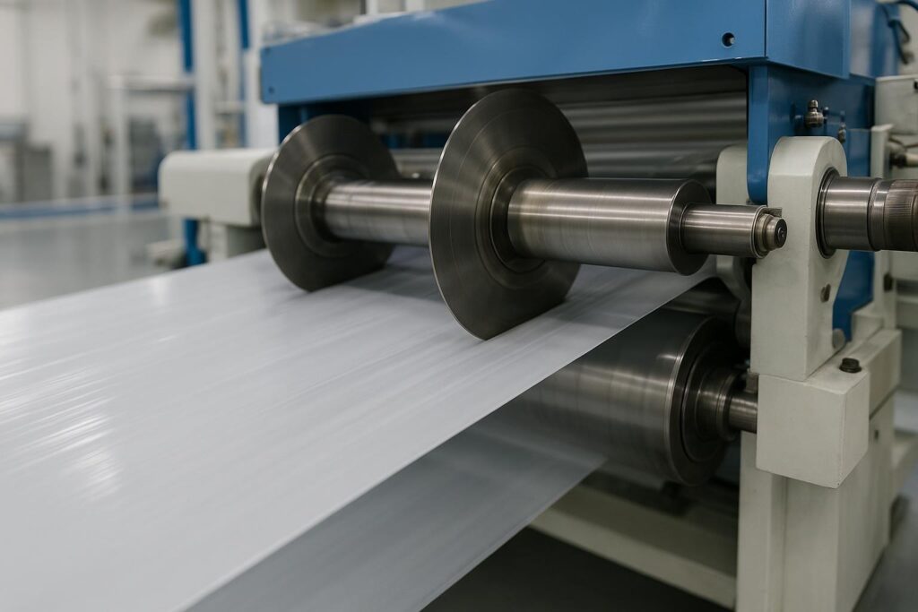
더 깔끔한 절단면과 그리고 긴 나이프 수명을 목표로 한다면, 가장 큰 성과는 단지 “더 날카로운 나이프”만으로 얻어지지 않습니다. 이는 재현 가능한 세팅 순서, 엄격한 검증, 그리고 SKU별 파라미터 범위를 명확히 보여주는 기록 일지에서 나옵니다.
본 가이드는 작업 현장용 체크리스트 형태로 작성되었습니다. 교체 작업마다 동일한 시행착오를 반복하지 않도록 무엇을 설정하고, 검증하며, 기록해야 하는지 설명합니다.
- 설정, 검증 및 기록할 항목 전단 슬리팅 개선을 위해
- 기대 효과: 더 깔끔한 절단면, 더 긴 블레이드 수명, 정밀한 슬릿 폭, 더 높은 OEE(설비 종합 효율)
- 필요 공구: 게이지, 회전계, 현미경, 토크 공구, 장력 데이터
전단 슬리팅의 원리
절단 메커니즘 및 접점
전단 슬리팅은 원형 가위처럼 작동합니다. 상부 수날 나이프와 하부 암날/앤빌 나이프가 제어된 접점(“절단점”)에서 만납니다. 절단 품질은 웹이 이동하고 장력이 변화하며 나이프 스택에 진동이 발생하는 동안 이 접점이 얼마나 안정적으로 유지되는지에 달려 있습니다.
이에 따른 두 가지 실무 규칙:
- 생산 현장에서는 웹을 깔끔하게 절단할 수 있는 딱 필요한 만큼의 맞물림.
- 생산 현장에서는 이 맞물림 상태를 안정적으로 유지하기 위한 가능한 한 최소한의 하중.
절단점이 이탈하거나(런아웃, 스페이서 오차, 진동) 맞물림이 과도할 때(과도한 오버랩/측압)는 종종 분진, 보풀, 발열, 조기 마모, 폭 변동과 같은 동일한 증상이 발생합니다.
경사각, 오버랩, 측압의 역할
이 세 가지를 단계별 프로세스로 생각하십시오. 한 번에 모두 조절하는 것이 아니라 순서대로 설정해야 합니다.
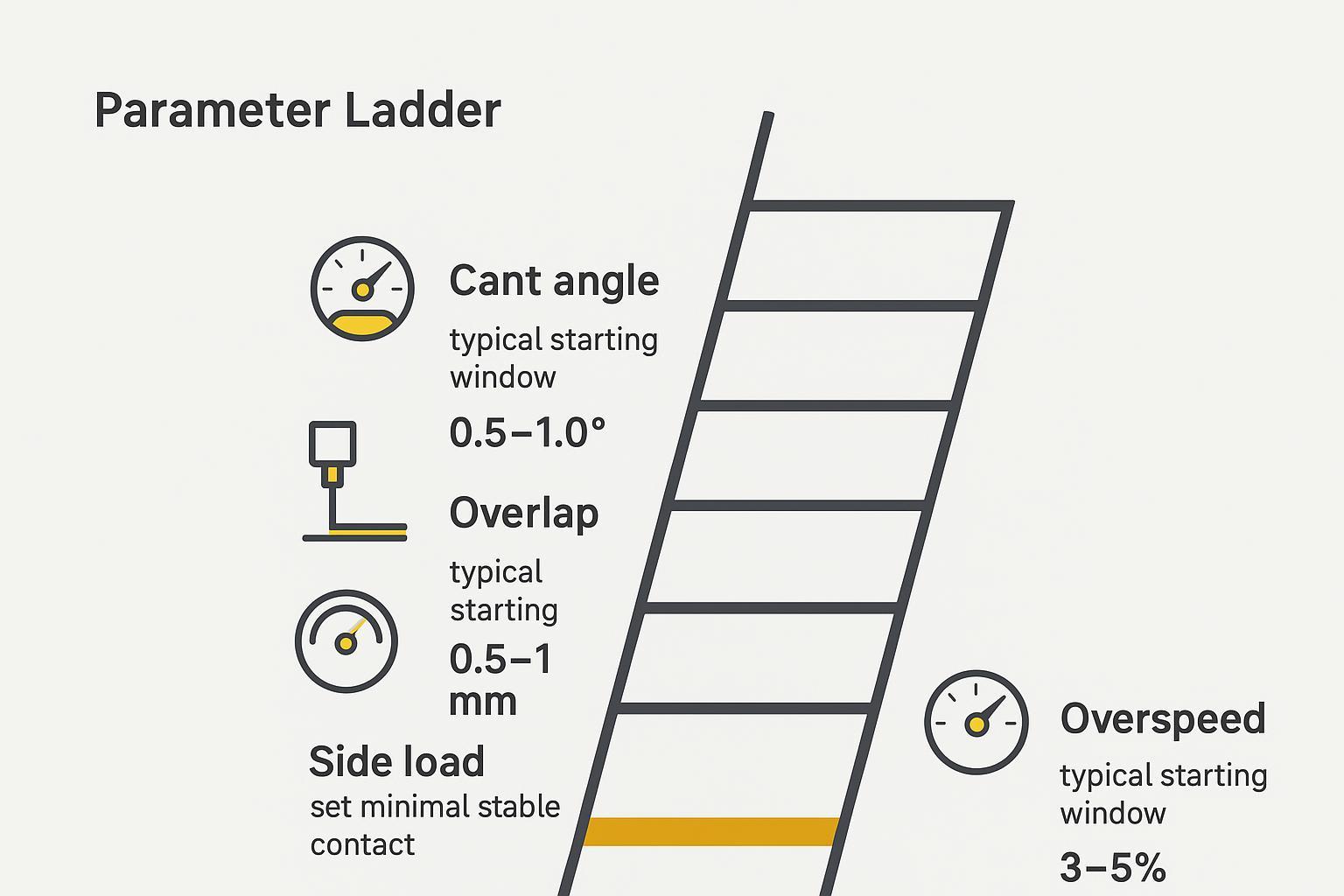
- Cant angle 경사각(Cant angle)은 나이프가 웹을横斷하여 만나는 방식을 결정합니다. 잘못된 경사각(특히 역경사/negative cant)은 접힘, 단선 및 절단 불안정을 유발할 수 있습니다. DIENES는 전단 슬리팅 문제 해결 노트에서 역경사를 지속적인 웹 단선 및 미절단의 주요 원인으로 지목합니다: 일반적인 전단 슬리팅 문제점.
- Overlap 오버랩(Overlap)은 상부 나이프가 하부 나이프의 접선 아래로 얼마나 깊이 침투하는지를 나타냅니다. 과도한 오버랩은 마모를 가속화하고 분진 및 에지 손상을 증가시킬 수 있으며, DIENES 역시 해당 가이드에서 과도한 오버랩을 거친 에지 및 분진 발생의 빈번한 원인으로 언급합니다.
- 측면 하중(Side load) 측압(Side load)은 나이프 접촉을 유지하는 측면 힘입니다. 측압이 너무 낮으면 나이프 접촉이 끊어지고, 너무 높으면 발열, 마모, 이빨 빠짐(chipping) 및 이지러진 에지가 발생합니다(이 역시 과도한 측압에 대한 DIENES의 경고와 일치함).
목표는 “더 강한 압력”이 아닙니다. 목표는 최소한의 힘으로 안정적인 접촉을 유지하는 것.
오버스피드, 장력, 모드 기초
두 가지 추가 변수가 고속 운전 시에도 깔끔한 절단면이 유지되는지를 결정합니다:
- 오버스피드 / 속도차: 많은 전단 슬리팅 세팅에서는 구동되는 하부 나이프를 상부 나이프보다 약간 빠르게 회전시킵니다(설계에 따라 보통 약 3~5% 범위). 이는 절단점을 안정적으로 유지하고 발열을 유발하는 슬립 및 마찰 현상을 방지하기 위함입니다.
- 웹 장력 및 이송 모드: 장력은 나이프로 들어오는 웹을 안정시켜 줍니다. 장력이 잘못되면 아무리 하루 종일 오버랩과 측압을 수정하더라도 웹 떨림, 에지 균열, 좌굴, 폭 드리프트 현상이 발생합니다.
핵심 요점핵심 요약: 전단 슬리팅을 제어된 접점 문제로 다루십시오. 최상의 절단면은 오버랩과 측압을 과도하게 높이는 것이 아니라 안정적인 정렬 + 최소한의 힘에서 나옵니다.
설정 및 검증(전단 슬리팅 세팅)
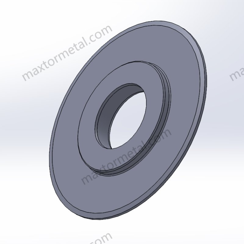
정렬, 경사각 및 오버랩 순서(전단 슬리팅 세팅 순서)
시행착오를 줄이려면 이 순서를 따르십시오. “완료 조건...” 점검 항목을 통해 작업 조가 바뀌어도 동일하게 재현 가능한 세팅을 구현할 수 있습니다.
- 나이프 조립체 세척 및 안착
- 홀더, 샤프트, 스페이서 및 나이프 단면을 세척합니다.
- 접촉면에 버(burr), 끼인 필름, 점착제가 없는지 확인합니다.
- 완료 시점: 스페이서/나이프가 흔들림 없이 완전히 안착되고 이물질 선이 보이지 않는 상태.
- 파라미터를 조정하기 전에 기계적 기준 상태를 확인하십시오.
- 베어링/홀더 상태 및 명확한 유격을 점검하십시오.
- 채터링/폭 변동이 반복적으로 발생하는 경우, 런아웃/TIR을 사후 조치 대상이 아닌 최우선 의심 요인으로 다루십시오.
- 완료 시점: 스테이션이 기계적으로 안정되어 있으며 측정할 준비가 되었습니다.
- 전단각(Cant angle) 설정(설정 후 고정)
- 해당 SKU 및 홀더 스타일의 확인된 시작 지점으로 전단각을 설정하십시오.
- 전단각 플레이트를 반대로 설치하지 않았는지 다시 확인하십시오(DIENES의 전단 슬리팅 문제 해결 지침에 명시된 바와 같이 음의 전단각은 전형적인 고장 원인입니다).
- 완료 시점: 전단각이 검증 및 기록되었으며, 편차를 방지하기 위해 하드웨어가 고정되었습니다.
- 오버랩 설정(최소치부터 시작)
- 소재와 두께에 알맞은 보수적인 오버랩 범위를 설정하여 시작하십시오.
- 처음부터 설정하는 경우, 많은 가이드에서 서브밀리미터(1mm 미만)에서 약 1mm 범위의 오버랩을 일반적인 시작 범위로 제시하지만, 올바른 목표치는 항상 안정적인 절단을 구현하는 최소 오버랩입니다..
- 완료 시점: 웹(소재)이 간헐적 이탈 없이 전단되며, 단면 검사 시 뜯김(chew) 자국이 관찰되지 않습니다.
- 측압(Side load)은 마지막에 추가(최소한의 안정적인 접촉)
- 속도 변화 중에도 접촉이 안정적으로 유지되는 수준까지만 측압을 올리십시오.
- 과도한 측압의 징후(마모 가속화, 발열, 칩핑, 분진)를 주의 깊게 관찰하십시오.
- 완료 시점: 절단면이 소음이나 급격한 발열 없이 생산 속도에서 안정적으로 유지됩니다.
측압 및 오버스피드 관리 범위
이 항목들을 단회성 설정이 아닌 제어된 범위로 다루십시오. SKU별로 기록하여 관리하십시오.
- 측압: 접촉 손실을 방지하는 가장 낮은 값으로 설정하십시오. 측압이 증가함에 따라 분진/보풀이 늘어난다면 절단 품질을 과도한 하중과 맞바꾸고 있을 가능성이 높습니다.
- 오버스피드: 하부 칼날이 구동되고 상부 칼날이 마찰 구동되는지 여부에 따라 하중 상태에서의 실제 속도비를 회전계(타코미터)로 확인하십시오. 자주 참조되는 시작 범위는 소수 퍼센트(보통 약 3–5%)입니다.
손상을 방지하는 두 가지 규칙:
- 절단을 유지하기 위해 점점 더 많은 측압이 필요한 경우, 칼날 무뎌짐, 런아웃 또는 오버랩 오류를 먼저 의심하십시오.
- 발열, 용융 또는 “엔젤 헤어”가 보이면 오버스피드와 오버랩을 다시 최소치 쪽으로 낮추고 장력 안정성을 확인하십시오.
스페이서, TIR 및 폭 점검
대부분의 “원인 불명의 불량”은 세 가지 항목을 측정하면 명확해집니다.
- 스페이서 적층 및 슬릿 폭
- 스페이서 두께와 적층 순서를 측정하십시오.
- 적층 상태가 목표 슬릿 폭 계획과 일치하는지 확인하십시오.
- Log: 스페이서 ID/위치, 목표 폭, 측정 폭.
- 칼날 스테이션의 런아웃/TIR
- 사용 중인 장비 작업 절차에 따라 다이얼 인디케이터로 관련 표면(홀더/샤프트/칼날)의 런아웃을 점검하십시오.
- 업계 참고 자료에서는 매우 엄격한 설계 목표값(예: 슬리팅 시스템 논의에서 축 방향 런아웃 약 0.002 in / 0.05 mm TIR, 반경 방향 런아웃 약 0.004 in / 0.10 mm TIR)을 제시하곤 합니다. 이를 점검 기준으로 참고하되—기계 OEM 사양을 최우선 기준 요구사항으로 적용하십시오. 측정된 런아웃이 OEM 목표치보다 현저히 나쁜 경우, 파라미터 조율만으로는 이를 완전히 보정할 수 없습니다.
- Log: 측정 지점, 측정값 및 수정 조치 사항.
- 확대 검사를 통한 절단면 점검
- 휴대용 현미경을 사용하여 슬릿 절단면의 미세 인열, 용융 또는 채터링 자국을 점검하십시오.
- 완료 시점: 슬릿 절단면이 반복적인 불량 패턴 없이 일관된 전단 상태를 나타냅니다.
전단 슬리팅 자주 묻는 질문(FAQ)
절단 품질을 가장 빠르게 개선하는 방법은 무엇입니까? 더 날카로운 칼날입니까, 아니면 더 나은 세팅입니까?
대부분의 라인에서 가장 빠른 품질 개선은 재현 가능한 세팅 순서 및 검증: 전단각 → 오버랩 → 측압 → 오버스피드 및 장력 안정성과 런아웃 점검에서 나옵니다. 날카로운 칼날도 도움이 되지만 다음 사항을 보상하지는 못합니다: 런아웃, 스페이서 오차 또는 과도한 물림량(engagement).
나이프에 과부하를 주지 않고 초기 오버랩을 선택하는 방법은 무엇인가요?
보수적인 초기 설정값에서 시작하여 적절한 안정적인 절단을 구현하는 최소 오버랩입니다.. 지점으로 조정하십시오. 오버랩이 커짐에 따라 보풀/분진/발열이 증가한다면 안정적인 작업 범위를 벗어났을 가능성이 높습니다. 체결량(engagement)을 늘려 기계적 문제(런아웃/스페이서)를 임시방편으로 해결하려 하는 것은 아닌지 확인하십시오.
측면 하중이 너무 높거나 낮은지 어떻게 확인합니까?
- 너무 낮을 때: 간헐적인 접촉 손실, 절단점 불안정성, 속도 변화 시 악화되는 절단면 불연속성.
- 너무 높을 때: 급격한 발열, 마모 가속화, 치핑, 더 큰 충격 소음 및 “뜯긴” 절단면.
목표는 생산 속도에서 안정적으로 유지되는 가장 낮은 측면 하중입니다..
장비에서 오버스피드를 확인하는 실용적인 방법은 무엇인가요?
HMI 설정값에만 의존하지 마십시오. 타코미터(회전계) 를 사용하여 부하 상태에서의 실제 속도 비를 확인하고, 해당 비율을 SKU별로 기록하십시오. 용융 현상이나 “엔젤 헤어”가 발생하면 오버스피드와 체결량을 최소치로 낮추고 장력 안정성을 다시 점검하십시오.
런아웃/TIR 및 스페이서 오차가 왜 “파라미터 문제”처럼 보이는 결함을 유발합니까?
미세한 주기적 흔들림이나 스페이서 두께 오차는 고속 운전 시 반복적인 결함 패턴 (채터 마크, 폭 변동, 주기적 절단면 손상)으로 나타납니다. 측정된 런아웃이 기계 OEM 사양, 을 초과하는 경우, 오버랩 및 측면 하중 조정은 마모를 가속화하면서 증상을 가리는 것일 뿐입니다.
교체 작업마다 동일한 시행착오를 반복하지 않으려면 설정을 어떻게 기록해야 합니까?
각 SKU를 제어된 공정 창으로 다루십시오. 최소한 다음 항목을 기록하십시오:
- 소재, 두께, 첨가제
- 라인 속도, 장력 설정값/실제값
- 캔트 각도, 오버랩, 측면 하중 방식/설정값, 오버스피드 비율
- 나이프 ID, 가동 시간, 최종 재연마 일자
- 지정된 지점에서의 런아웃/TIR 측정값
- 절단면 검사 메모(가능한 경우 현미경 사진 1장 포함)
결함이 발생했을 때 가장 먼저 시도해야 할 조치는 무엇인가요?
“가장 리스크가 적은 조치부터” 방식을 적용하십시오:
- 보풀/분진 발생 시: 오버랩을 최소치로 감소, 측면 하중 감소, 날 날카로움 및 런아웃 확인.
- 용융/엔젤 헤어 발생 시: 타코미터로 오버스피드 비를 확인하고, 오버랩/측면 하중을 줄이며, 장력을 안정화하십시오.
- 채터링/폭 변동: 맞물림을 조정하기 전에 런아웃/TIR을 측정하고 스페이서 스택을 확인하십시오.
라인이 가동 중일 때 작업자가 나이프 스테이션을 조정할 수 있습니까?
아니요. 안전과 재현성을 위해 나이프 스테이션 조정은 통제된 정비 작업으로 취급해야 합니다. 라인을 정지하고 LOTO를 적용한 후, 잔류 에너지가 0인지 확인하고 조정하십시오.. 사업장 절차 및 장비 OEM 권장 사항을 따르십시오.
깔끔한 절단면 품질 문제 해결
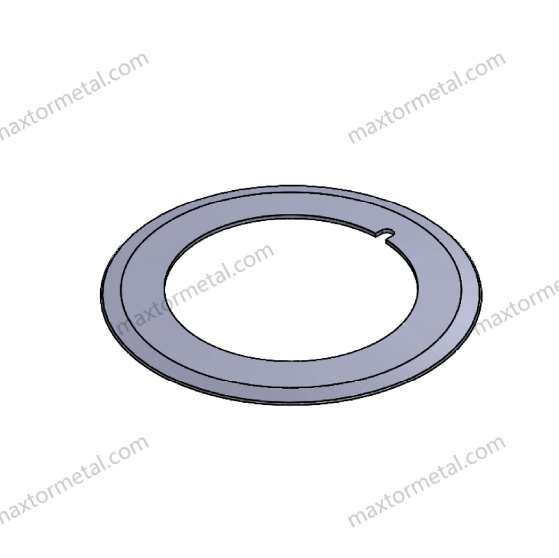
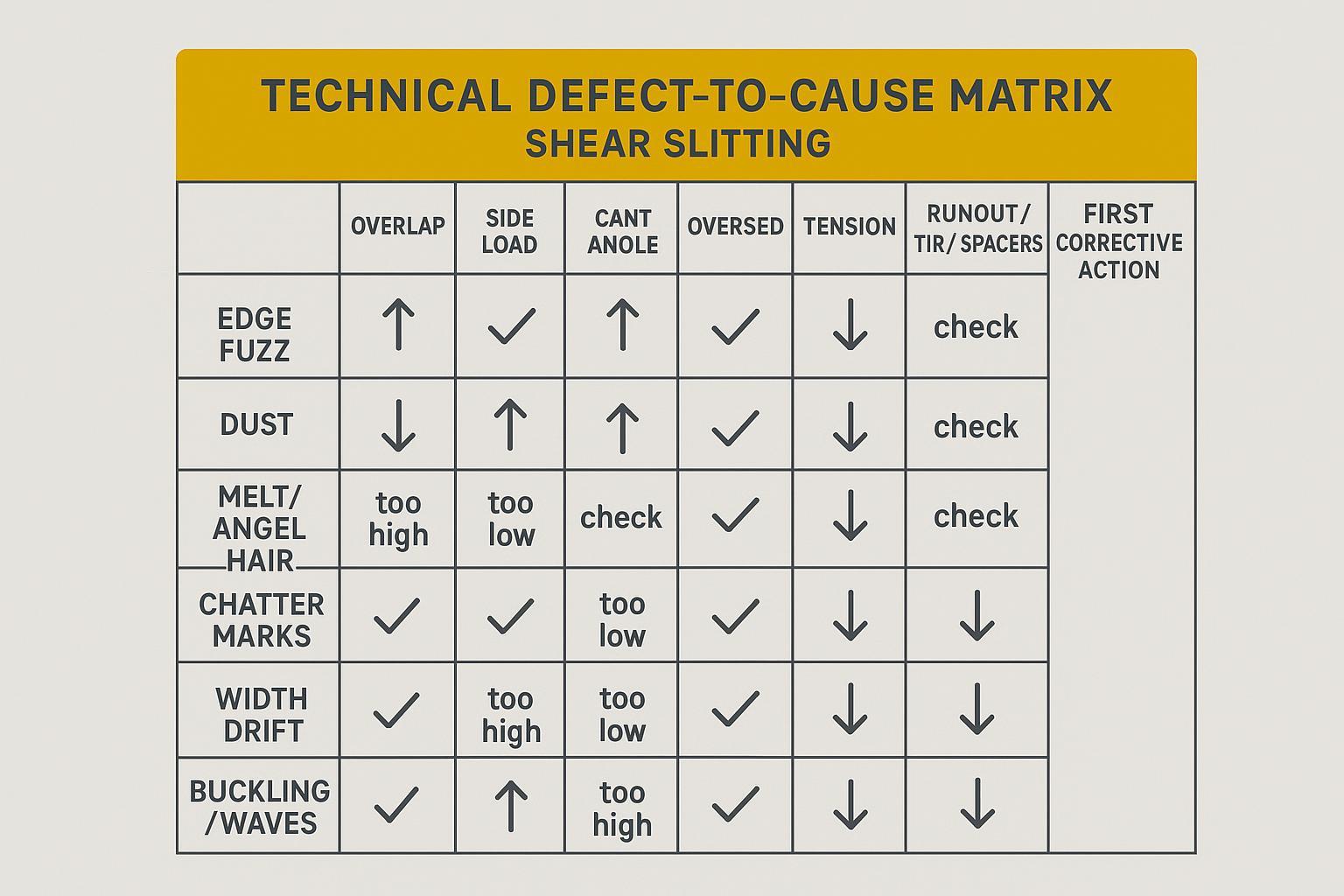
보풀, 분진, 용융: 원인 및 해결 방법
신속한 진단부터 시작하십시오. 이 세 가지 결함은 주로 과도한 맞물림이나 불안정한 접촉으로 인해 발생합니다.
- 보풀 / 거친 단면
- 추정 원인: 과도한 오버랩, 과도한 측면 하중, 무뎌지거나 잘못 연마된 칼날, 런아웃.
- 1차 조치 사항: 오버랩을 최소한으로 줄임, 측면 하중 줄임, 날카로움 및 연마 품질 확인, 런아웃 측정.
- 먼지
- 추정 원인: 과도한 오버랩(흔히 나타나는 초기 징후), 무뎌진 날, 진동.
- 1차 조치 사항: 오버랩 최소화, 캔트(경사각) 확인, 진동 점검, 웹 떨림 여부 확인.
- 용융 / “엔젤 헤어”
- Likely causes: friction heat from slip-and-rub (overspeed mismatch), too much engagement, unstable tension.
- First fixes: verify speed ratio with a tach; reduce overlap and side load; stabilize tension and web path.
DIENES summarizes several of these root causes (cant mistakes, overlap, side load, tension, runout, vibration) in its field-focused list of common problems found in shear slitting.
Chatter and width drift: root checks
Chatter marks and width drift are often mechanical or stack-related before they’re “parameter problems.”
Root checks in order:
- Runout/TIR and bearing condition (a small cyclic wobble becomes a visible pattern at speed)
- Spacer stack accuracy (thickness errors, burrs, wrong order)
- Knife condition (micro-chipping can create periodic marks)
- Vibration sources (loose holders, resonance at certain speeds)
If you only change overlap/side load to compensate, you may temporarily mask chatter while accelerating wear.
Buckling and waves: overspeed/tension
Buckling, waves, or edge camber usually point to a web-handling stability issue:
- If the web is too tight 또는 unevenly tensioned, you can see width instability and edge distortion.
- If the web is too loose approaching the knives, it can sag and “steer” into the cut.
Corrections to try:
- Re-balance unwind/rewind tension zones.
- Confirm spreader/roller alignment.
- Re-check overspeed and side load after tension is stable.
최적화 및 유지보수
Parameter ladder and data logging
Once the line is stable, the fastest way to improve OEE is to stop “tuning by memory.” Build a simple log by SKU and keep it brutally consistent.
Log these fields every time:
- Material + thickness + additives (anything that changes cut behavior)
- Line speed and web tension setpoints (and actuals if available)
- Cant angle, overlap, side load method (pressure/torque setting), overspeed ratio
- Knife IDs (top/bottom), run hours, and last regrind date
- Measured runout/TIR at defined points
- Edge inspection notes (microscope photo if possible)
Then manage the ladder:
- Only change one rung at a time (cant → overlap → side load → overspeed).
- Record the result and keep the “good window” for that SKU.
If you want a deeper read on lifespan drivers, MAXTOR’s internal guide on how to extend circular slitting blade lifespan pairs well with this setup-first approach.
Metallurgy, coatings, edge prep
If setup is stable but life is still short, you’re usually looking at materials, surface finish, or edge prep — not more force.
Focus your discussion on measurable specs:
- Steel selection and heat treatment consistency (hardness and microstructure must match the duty cycle)
- 코팅 (when friction/adhesion is the limiter)
- 모서리 준비 및 표면 마감 (rough finish can increase rubbing and dust)
A practical maintenance note: resharpening quality matters as much as resharpening frequency. DIENES’ note on knife resharpening and its impact on shear slitting quality emphasizes restoring geometry and controlling finish; they also highlight that bottom-knife runout control becomes more critical as speed increases.
Evidence note (what we can—and can’t—quantify publicly)
Many industry resources describe which parameters drive edge quality and knife life, but public, production-scale case studies with full before/after OEE or knife-life percentages are often not published. Where public numbers exist, they’re commonly from controlled experiments rather than plant-wide KPI reports.
For example, experimental work on aluminum alloy shear slitting reports that burr formation trends strongly with clearance, rake angle, and speed, and identifies process windows that minimize burrs (see: https://pmc.ncbi.nlm.nih.gov/articles/PMC7412372/). Use this type of data as directional guidance, then validate your final window with your own line measurements and defect logs.
This is also where MAXTOR METAL’s process support matters in a non-marketing way:
- QC and traceability: incoming material checks, in-process inspection points, and documentation help you avoid “mystery steel” and inconsistent hardness from batch to batch.
- Metallurgy support: matching steel/heat treat/coating to your film or textile duty cycle is often the lowest-cost way to reduce changeovers.
- Import support: for plants that can’t afford stockouts, one-stop shipping and customs support reduces schedule risk during high-mix production.
For a tolerances-focused view, see MAXTOR’s guide on slitter knives tolerances, materials, and grinding.
Resharpening and holder care
A knife that’s “sharp” but ground poorly can behave like a dull knife.
Maintenance actions that protect edge quality:
- Verify regrind restores the correct bevel/profile and keeps grinding marks concentric.
- Avoid overheating during grinding (thermal damage kills life).
- Measure and record post-grind runout; don’t reinstall a knife stack that fails your runout check.
- Keep holders clean, faces flat, and torque practices consistent.
If you need a maintenance-oriented companion piece, MAXTOR’s overview of slitting blade wear and repair can be linked for your internal SOP library.
안전 및 표준 작업 절차(SOP)
PPE, LOTO, handling blades
Shear slitting stations combine sharp tooling, rotating inertia, and stored energy. Treat changeovers like a controlled maintenance task, not a quick tweak.
최소 기대치:
- Wear cut-resistant gloves and eye protection during handling.
- Use LOTO and verify zero-energy state before reaching into the station.
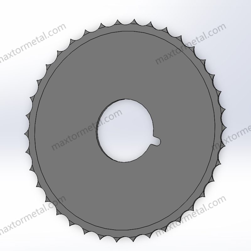
- Handle knives with the right fixtures; don’t “pinch carry” circular knives.
⚠️ 경고: Don’t troubleshoot with hands near rotating knives. If a defect requires adjustment, stop, lock out, verify, then adjust.
Changeover checklists
Use a short checklist your team will actually follow.
SOP template tip: Add a header to your checklist so it becomes a controlled document.
- Document name: Shear Slitting Setup & Verification Checklist
- 버전: 버전 1.0
- Effective date: 2026-05-04
- Applies to: (machine model/knife station type), (material families), (thickness range), (speed range)
- Owner: Process Engineering / Maintenance
- Safety requirement: LOTO required for all adjustments at the knife station
- Clean and inspect holders/shafts/spacers
- Confirm cant orientation (avoid negative cant)
- Set and record cant
- 오버랩 설정(최소치부터 시작)
- Apply side load (minimal stable contact)
- Confirm overspeed with a tach
- Verify spacer stack and target widths
- Measure runout/TIR at defined points
- Perform a controlled test cut and inspect edge under magnification
Verification and restart sign-off
Before releasing the line back to production:
- Record the “as-left” settings and measured checks.
- Capture one microscope image of the edge as the baseline for that SKU.
- If the station is sensitive, set a short re-check interval (for example, after the first master roll) and log whether the edge stayed stable.
결론
If you want clean edges and longer knife life, focus on the order of operations:
- Parameter order matters: cant → overlap → side load → overspeed.
- Minimal force wins: set only what you need to keep a stable cut.
- Document the windows: log settings, measurements, and edge observations by SKU.
다음 단계:
- Run one baseline setup with a tight log.
- Adjust one variable at a time by SKU.
- Track knife life, waste rate, and changeover time so your “best window” is obvious.
If you’d like, you can share your material (film/textile type, thickness range, line speed, and current defect photos), and MAXTOR METAL can help you sanity-check the likely parameter windows and the knife spec path (steel/heat treatment/coating) before you burn another shift on trial-and-error.
Jerry Chu 입니다 Technical Support Specialist ~에 애프터 서비스 ~에 맥스터 메탈 ~와 함께 10 years of cross-industry application experience (e.g., papermaking, plastics shredding, metal coil slitting, woodworking). He supports plants in troubleshooting real-world converting issues such as burrs, fuzzy edges, and excessive dust, and helps teams standardize setup and verification practices.
신임장: PMP, CMRP.
Company quality system: MAXTOR METAL operates under a quality management system (e.g., ISO 9001) and applies incoming material inspection and in-process checks to support consistent knife performance.
Scope & safety note
This guide is intended as a starting-point checklist for shear slitting setup and verification. Always follow your machine OEM recommendations, your facility’s safety procedures, and trained operator requirements. Do not adjust rotating knife stations while running—stop, apply LOTO, verify zero energy, then adjust.

 English
 Spanish
 Italian
 French
 Portuguese
 Russian
 German
 Arabic
 Hindi
 Vietnamese
 Indonesian
 Japanese
 Korean