


Wenn Sie sauberere Schnittkanten anstreben, und eine längere Messerstandzeit, dann erzielen Sie die größten Erfolge meist nicht allein durch “schärfere Messer”. Sie resultieren aus einer reproduzierbaren Einstellreihenfolge, einer präzisen Überprüfung und einem Protokollbuch, das Ihre Parameterfenster je nach SKU klar vorgibt.
Dieser Leitfaden ist als Checkliste für die Werkstatt konzipiert: was einzustellen, was zu überprüfen und was zu protokollieren ist, damit Sie nicht bei jedem Werkzeugwechsel dieselben Fehler wiederholen müssen.
- Was Sie einstellen, überprüfen und protokollieren sollten zur Optimierung des Scherenschnitt-Längsschneidens
- Erwartete Vorteile: sauberere Kanten, längere Standzeit der Messer, engere Schnittbreitentoleranzen, höhere OEE
- Benötigte Werkzeuge: Messlehren, Tachometer, Mikroskop, Drehmomentwerkzeuge, Bahnspannungsdaten
Prinzipien des Scherenschnitt-Längsschneidens
Schnittmechanik und Kontaktpunkt
Das Scherenschnitt-Längsschneiden funktioniert wie eine Rundschere: Ein oberes Obermesser und ein unteres Untermesser/Ambossmesser treffen an einem kontrollierten Kontaktpunkt (dem “Schnittpunkt”) aufeinander. Ihre Schnittqualität hängt davon ab, wie stabil dieser Kontaktpunkt bleibt, während sich die Warenbahn bewegt, sich die Bahnspannung ändert und der Messersatz Vibrationen ausgesetzt ist.
Daraus ergeben sich zwei praktische Regeln:
- Du willst gerade so viel Eintauchtiefe, wie nötig ist, um die Bahn sauber zu schneiden.
- Du willst so wenig Kraft wie möglich, um diese Eintauchtiefe stabil zu halten.
Wenn der Schnittpunkt wandert (Rundlauffehler, Distanzringfehler, Vibrationen) oder die Eintauchtiefe zu groß ist (zu viel Überlappung/Anpressdruck), treten häufig dieselben Symptome auf: Staub, Flusenbildung, Hitzeentwicklung, vorzeitiger Verschleiß und Breitenabweichungen.
Die Rollen von Scherwinkel, Überlappung und Anpressdruck
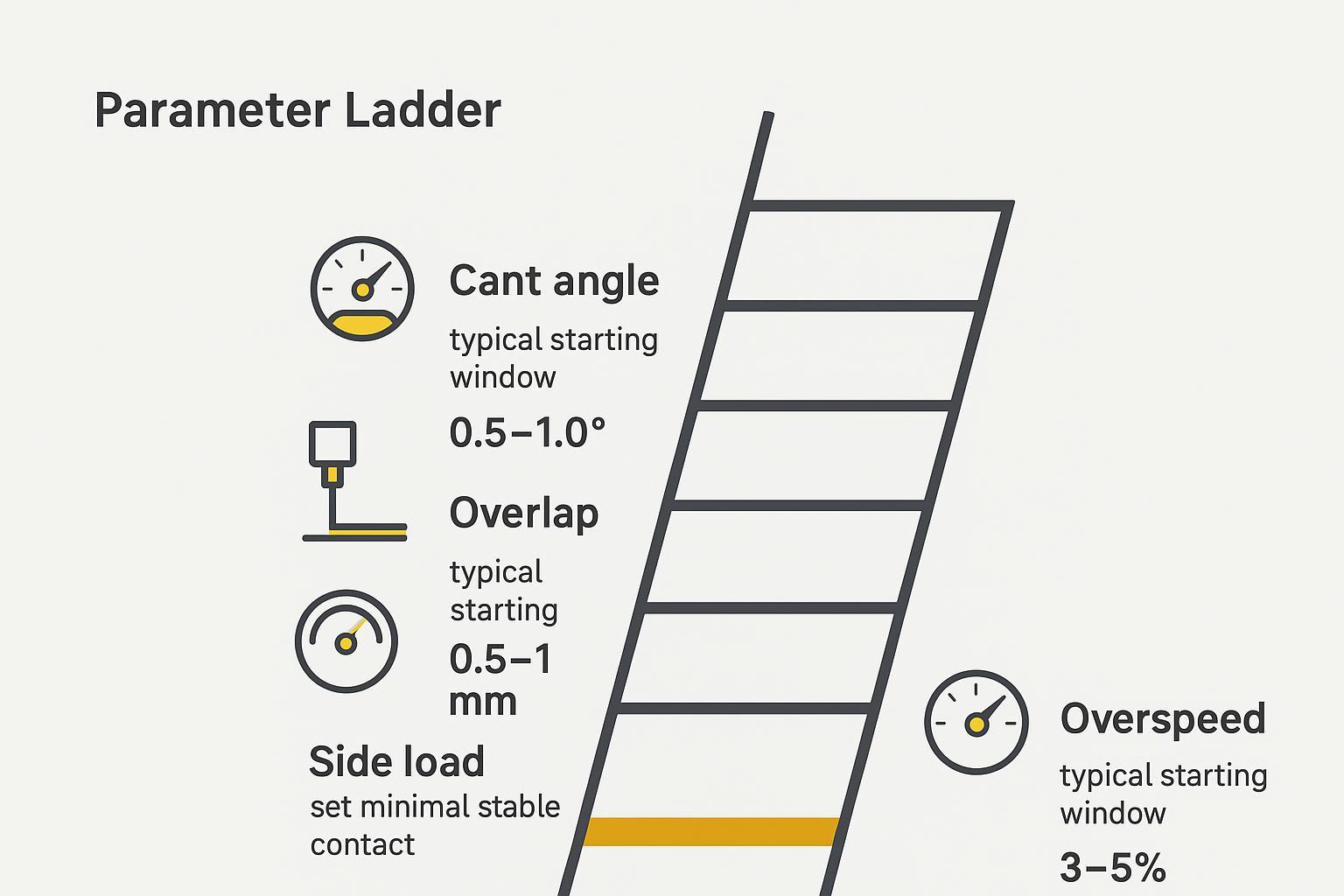
Betrachten Sie diese drei Parameter wie eine Leiter. Sie stellen sie nicht alle auf einmal ein, sondern nacheinander in einer bestimmten Reihenfolge.
- Winkel nicht wählbar bestimmt, wie die Messer über die Bahn hinweg aufeinander treffen. Ein falscher Scherwinkel (insbesondere ein negativer Scherwinkel) kann zu Faltenbildung, Bahnrissen und einem instabilen Schnitt führen. DIENES hebt den negativen Scherwinkel in seinen Fehlerbehebungshinweisen zu häufigen Problemen beim Scherenschnitt-Längsschneiden.
- Überlappen als häufige Ursache für anhaltende Bahnrisse und mangelhafte Schnitte hervor. Die Überlappung bestimmt, wie weit das Obermesser unter die Tangentenlinie des Untermessers eintaucht. Eine zu große Überlappung beschleunigt den Verschleiß und kann Staubbildung sowie Kantenschäden verstärken; DIENES nennt eine übermäßige Überlappung in derselben Anleitung zur Fehlerbehebung ebenfalls als häufige Ursache für faserige Kanten und Staub.
- Der Anpressdruck (Seitendruck) ist die seitliche Kraft, die den Kontakt der Messer aufrechterhält. Ist sie zu gering, verlieren die Messer den Kontakt; ist sie zu hoch, entstehen Hitze, Verschleiß, Ausbrüche und “zerkaute” Kanten (was sich ebenfalls mit den Warnungen von DIENES vor zu hohem Anpressdruck deckt).
Das Ziel ist nicht “mehr Druck”. Das Ziel ist stabiler Kontakt bei minimaler Kraft..
Grundlagen zu Voreilung, Bahnspannung und Betriebsmodus
Zwei weitere Variablen entscheiden darüber, ob Ihr sauberer Schnitt auch bei hoher Geschwindigkeit sauber bleibt:
- Voreilung / Geschwindigkeitsdifferenz: Bei vielen Scherenschnitt-Systemen läuft das angetriebene Untermesser etwas schneller als das Obermesser (häufig wird ein kleiner Prozentbereich von ca. ~3–5% genannt, je nach Konstruktion). Ziel ist es, den Schnittpunkt stabil zu halten und Schlupf- sowie Reibungszustände zu vermeiden, die Hitze erzeugen.
- Bahnspannung und Bahnführung: Die Bahnspannung stabilisiert die Warenbahn im Einlauf der Messer. Wenn die Bahnspannung nicht stimmt, können Sie Überlappung und Anpressdruck den ganzen Tag lang korrigieren und werden dennoch Flattern, Kantenrisse, Knicken und Breitenabweichungen feststellen.
Wichtigste Erkenntnis: Betrachten Sie das Scherenschnitt-Längsschneiden als ein Problem des kontrollierten Kontaktpunkts. Die beste Kante erzielen Sie durch eine stabile Ausrichtung + minimale Kraft, nicht durch das Erhöhen von Überlappung und Anpressdruck.
Einrichtung und Überprüfung (Scherenschnitt-Einstellung)
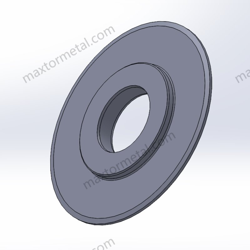
Reihenfolge für Ausrichtung, Scherwinkel und Überlappung (Einstellreihenfolge beim Scherenschnitt)
Nutzen Sie diese Reihenfolge, um zeitaufwendiges Ausprobieren zu reduzieren. Die “Erledigt, wenn...”-Prüfungen sorgen dafür, dass die Einstellung über alle Schichten hinweg reproduzierbar ist.
- Messersatz reinigen und positionieren
- Reinigen Sie Halter, Wellen, Distanzringe und Messerflächen.
- Stellen Sie sicher, dass sich keine Grate, Folienreste oder Klebstoffrückstände auf den Kontaktflächen befinden.
- Erledigt, wenn: Distanzringe/Messer liegen vollständig plan auf, wackeln nicht und weisen keine sichtbaren Schmutzränder auf.
- Mechanische Ausgangsbasis überprüfen, bevor Parameter geändert werden
- Überprüfen Sie den Zustand der Lager/Halter und achten Sie auf offensichtliches Spiel.
- Wenn Sie wiederkehrendes Rattern oder Breitenabweichungen feststellen, behandeln Sie den Rundlauffehler/TIR als Hauptverdächtigen und nicht als Nebensache.
- Erledigt, wenn: die Station mechanisch stabil und bereit für die Messung ist.
- Scherwinkel einstellen (und anschließend arretieren)
- Set cant to your known starting point for that SKU and holder style.
- Re-check that you didn’t install cant plates backwards (negative cant is a classic failure mode, as noted in DIENES’ shear slitting troubleshooting guidance).
- Erledigt, wenn: cant is verified and recorded, and the hardware is locked to prevent drift.
- Set overlap (start minimal)
- Start with a conservative overlap window appropriate for your material and thickness.
- If you’re starting from scratch, many guides cite overlap in the sub‑millimeter to ~1 mm range as a typical starting window for certain configurations — but the correct target is always the minimum overlap that produces a stable cut.
- Erledigt, wenn: the web shears without intermittent disengagement, and edge inspection shows no “chew” marks.
- Add side load last (minimal stable contact)
- Increase side load only until contact is stable through speed changes.
- Watch for the telltales of too much side load: faster wear, heat, chipping, dust.
- Erledigt, wenn: edge stays stable at production speed with no audible impact and no rapid heat buildup.
Side load and overspeed windows
Treat these as controlled windows, not “set and forget.” Record them by SKU.
- Side load: Set to the lowest value that prevents contact loss. If you see fuzz/dust increase as side load increases, you’re likely trading edge quality for force.
- Overspeed: Use a tach to confirm actual speed ratio under load. A commonly referenced starting window is a few percent (often ~3–5%) depending on whether the bottom knife is driven and the top is friction-driven.
Two rules that prevent damage:
- If you need more and more side load to keep a cut, suspect dullness, runout, or overlap error first.
- If you see heat/melt/“angel hair,” bring overspeed and overlap back toward minimums and confirm tension stability.
Spacer, TIR, and width checks
Most “mystery defects” become obvious when you measure three things.
- Spacer stack and slit width
- Measure spacer thickness and stack order.
- Confirm the stack matches the target slit width plan.
- Protokoll: spacer IDs/positions, target widths, measured widths.
- Runout/TIR at the knife station
- Use a dial indicator to check runout on relevant surfaces (holder/shaft/knife) per your equipment practice.
- Industry references often describe very tight design targets (for example, axial runout on the order of 0.002 in / 0.05 mm TIR and radial runout on the order of 0.004 in / 0.10 mm TIR in slitting system discussions). Use those as a reality check—but treat your machine OEM specification as the controlling requirement. If your measured runout is materially worse than the OEM target, parameter tuning won’t fully compensate.
- Protokoll: measurement points, readings, and any corrective action.
- Edge inspection under magnification
- Use a handheld microscope to check the slit edge for micro-tears, melt, or chatter marks.
- Erledigt, wenn: the slit edge shows a consistent shear with no recurring defect pattern.
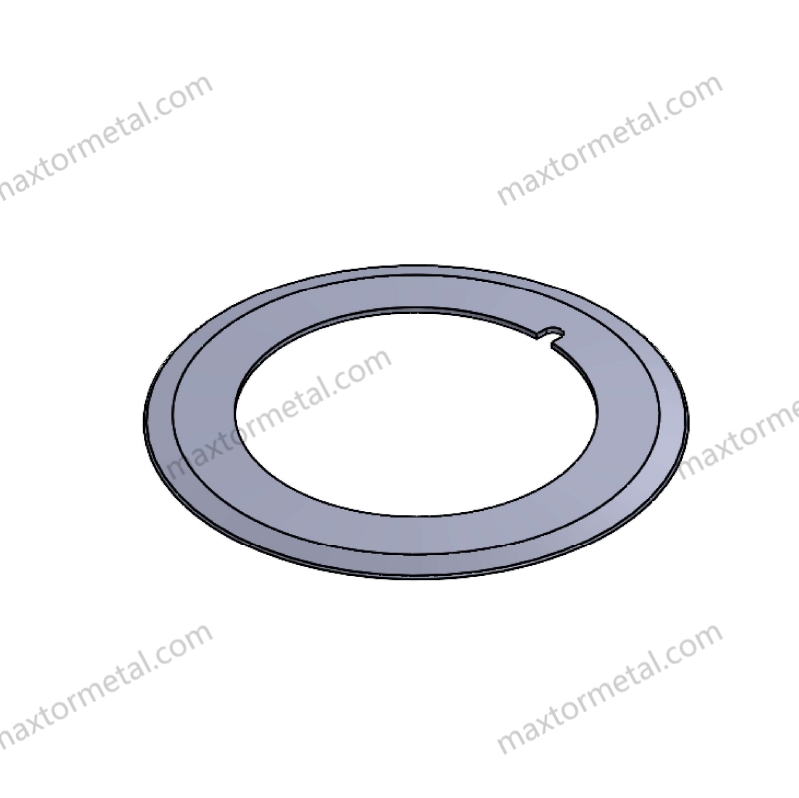
Shear slitting FAQ
1) What’s the fastest way to improve cut quality—sharper knives or better setup?
In most lines, the fastest gains come from a repeatable setup order and verification: cant → overlap → side load → overspeed, plus tension stability and runout checks. Sharper knives help, but they won’t compensate for runout, spacer errors, or excessive engagement.
2) How do I choose a starting overlap without overloading the knives?
Use a conservative starting point, then work toward the minimum overlap that produces a stable cut. If fuzz/dust/heat increases as overlap increases, you’re likely beyond the stable window. Confirm you’re not “fixing” a mechanical problem (runout/spacers) by adding engagement.
3) How do I know if side load is too high or too low?
- Too low: intermittent contact loss, cut point instability, edge intermittency that gets worse with speed changes.
- Too high: rapid heat, accelerated wear, chipping, louder impact noise, and “chewed” edges.
The target is the lowest side load that stays stable at production speed.
4) What’s a practical way to confirm overspeed on the machine?
Don’t rely on the HMI setpoint alone. Use a tach to confirm the actual speed ratio under load, then log that ratio by SKU. If you see melt/“angel hair,” bring overspeed and engagement back toward minimums and re-check tension stability.
5) Why do runout/TIR and spacer errors cause defects that look like “parameter problems”?
A small cyclic wobble or a spacer thickness error becomes a repeating defect pattern at speed (chatter marks, width drift, periodic edge damage). If the measured runout exceeds your machine OEM specification, overlap and side load changes may only mask symptoms while accelerating wear.
6) How should we record settings so we don’t re-learn the same lessons every changeover?
Treat each SKU like a controlled process window. At minimum, log:
- Material, thickness, additives
- Line speed, tension setpoints/actuals
- Cant, overlap, side load method/setting, overspeed ratio
- Knife IDs, run hours, last regrind date
- Runout/TIR readings at defined points
- Edge inspection notes (one microscope photo if possible)
7) When a defect appears, what’s the first corrective action to try?
Use a “lowest-risk first” approach:
- Fuzz/dust: reduce overlap toward minimum; reduce side load; verify sharpness and runout.
- Melt/angel hair: confirm overspeed ratio with a tach; reduce overlap/side load; stabilize tension.
- Chatter/width drift: measure runout/TIR and verify spacer stack before adjusting engagement.
8) Can operators adjust the knife station while the line is running?
No. For safety and repeatability, treat knife-station adjustments as a controlled maintenance action: stop the line, apply LOTO, verify zero energy, then adjust. Follow your facility procedures and the machine OEM recommendations.
Troubleshooting clean edges
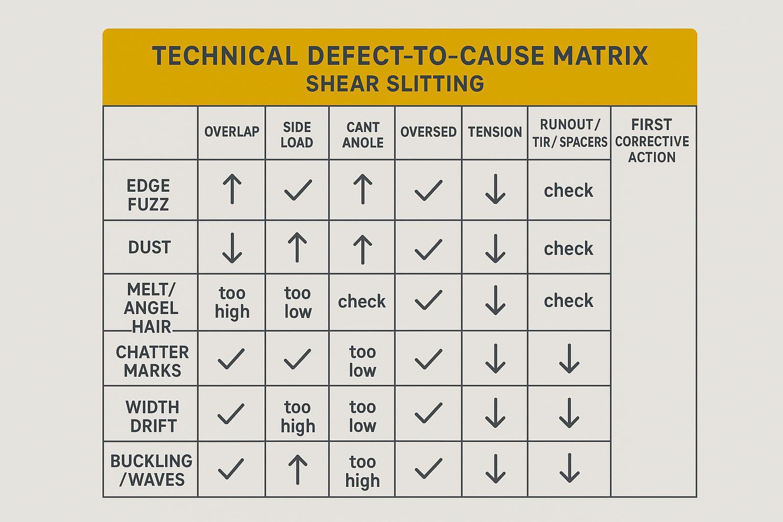
Fuzz, dust, melt: causes and fixes
Start with a fast triage. These three defects often come from too much engagement or unstable contact.
- Fuzz / hairy edge
- Likely causes: overlap too high, side load too high, dull/incorrectly sharpened knives, runout.
- First fixes: reduce overlap toward minimum; reduce side load; verify sharpness and grind quality; measure runout.
- Dust
- Likely causes: excessive overlap (often an early indicator), dull edges, vibration.
- First fixes: minimize overlap; confirm cant; inspect for vibration; verify the web isn’t fluttering.
- Melt / “angel hair”
- Likely causes: friction heat from slip-and-rub (overspeed mismatch), too much engagement, unstable tension.
- First fixes: verify speed ratio with a tach; reduce overlap and side load; stabilize tension and web path.
DIENES summarizes several of these root causes (cant mistakes, overlap, side load, tension, runout, vibration) in its field-focused list of common problems found in shear slitting.
Chatter and width drift: root checks
Chatter marks and width drift are often mechanical or stack-related before they’re “parameter problems.”
Root checks in order:
- Runout/TIR and bearing condition (a small cyclic wobble becomes a visible pattern at speed)
- Spacer stack accuracy (thickness errors, burrs, wrong order)
- Knife condition (micro-chipping can create periodic marks)
- Vibrationsquellen (loose holders, resonance at certain speeds)
If you only change overlap/side load to compensate, you may temporarily mask chatter while accelerating wear.
Buckling and waves: overspeed/tension
Buckling, waves, or edge camber usually point to a web-handling stability issue:
- If the web is too tight oder unevenly tensioned, you can see width instability and edge distortion.
- If the web is too loose approaching the knives, it can sag and “steer” into the cut.
Corrections to try:
- Re-balance unwind/rewind tension zones.
- Confirm spreader/roller alignment.
- Re-check overspeed and side load after tension is stable.
Optimization and maintenance
Parameter ladder and data logging
Once the line is stable, the fastest way to improve OEE is to stop “tuning by memory.” Build a simple log by SKU and keep it brutally consistent.
Log these fields every time:
- Material + thickness + additives (anything that changes cut behavior)
- Line speed and web tension setpoints (and actuals if available)
- Cant angle, overlap, side load method (pressure/torque setting), overspeed ratio
- Knife IDs (top/bottom), run hours, and last regrind date
- Measured runout/TIR at defined points
- Edge inspection notes (microscope photo if possible)
Then manage the ladder:
- Only change one rung at a time (cant → overlap → side load → overspeed).
- Record the result and keep the “good window” for that SKU.
If you want a deeper read on lifespan drivers, MAXTOR’s internal guide on how to extend circular slitting blade lifespan pairs well with this setup-first approach.
Metallurgy, coatings, edge prep
If setup is stable but life is still short, you’re usually looking at materials, surface finish, or edge prep — not more force.
Focus your discussion on measurable specs:
- Steel selection and heat treatment consistency (hardness and microstructure must match the duty cycle)
- Beschichtungen (when friction/adhesion is the limiter)
- Edge prep and surface finish (rough finish can increase rubbing and dust)
A practical maintenance note: resharpening quality matters as much as resharpening frequency. DIENES’ note on knife resharpening and its impact on shear slitting quality emphasizes restoring geometry and controlling finish; they also highlight that bottom-knife runout control becomes more critical as speed increases.
Evidence note (what we can—and can’t—quantify publicly)
Many industry resources describe which parameters drive edge quality and knife life, but public, production-scale case studies with full before/after OEE or knife-life percentages are often not published. Where public numbers exist, they’re commonly from controlled experiments rather than plant-wide KPI reports.
For example, experimental work on aluminum alloy shear slitting reports that burr formation trends strongly with clearance, rake angle, and speed, and identifies process windows that minimize burrs (see: https://pmc.ncbi.nlm.nih.gov/articles/PMC7412372/). Use this type of data as directional guidance, then validate your final window with your own line measurements and defect logs.
This is also where MAXTOR METAL’s process support matters in a non-marketing way:
- QC and traceability: incoming material checks, in-process inspection points, and documentation help you avoid “mystery steel” and inconsistent hardness from batch to batch.
- Metallurgy support: matching steel/heat treat/coating to your film or textile duty cycle is often the lowest-cost way to reduce changeovers.
- Import support: for plants that can’t afford stockouts, one-stop shipping and customs support reduces schedule risk during high-mix production.
For a tolerances-focused view, see MAXTOR’s guide on slitter knives tolerances, materials, and grinding.
Resharpening and holder care
A knife that’s “sharp” but ground poorly can behave like a dull knife.
Maintenance actions that protect edge quality:
- Verify regrind restores the correct bevel/profile and keeps grinding marks concentric.
- Avoid overheating during grinding (thermal damage kills life).
- Measure and record post-grind runout; don’t reinstall a knife stack that fails your runout check.
- Keep holders clean, faces flat, and torque practices consistent.
If you need a maintenance-oriented companion piece, MAXTOR’s overview of slitting blade wear and repair can be linked for your internal SOP library.
Safety and SOPs
PPE, LOTO, handling blades
Shear slitting stations combine sharp tooling, rotating inertia, and stored energy. Treat changeovers like a controlled maintenance task, not a quick tweak.
Mindestanforderungen:
- Wear cut-resistant gloves and eye protection during handling.
- Use LOTO and verify zero-energy state before reaching into the station.
- Handle knives with the right fixtures; don’t “pinch carry” circular knives.
⚠️ Warnung: Don’t troubleshoot with hands near rotating knives. If a defect requires adjustment, stop, lock out, verify, then adjust.
Changeover checklists
Use a short checklist your team will actually follow.
SOP template tip: Add a header to your checklist so it becomes a controlled document.
- Document name: Shear Slitting Setup & Verification Checklist
- Version: v1.0
- Effective date: 2026-05-04
- Applies to: (machine model/knife station type), (material families), (thickness range), (speed range)
- Owner: Process Engineering / Maintenance
- Safety requirement: LOTO required for all adjustments at the knife station
- Clean and inspect holders/shafts/spacers
- Confirm cant orientation (avoid negative cant)
- Set and record cant
- Set overlap (start minimal)
- Apply side load (minimal stable contact)
- Confirm overspeed with a tach
- Verify spacer stack and target widths
- Measure runout/TIR at defined points
- Perform a controlled test cut and inspect edge under magnification
Verification and restart sign-off
Before releasing the line back to production:
- Record the “as-left” settings and measured checks.
- Capture one microscope image of the edge as the baseline for that SKU.
- If the station is sensitive, set a short re-check interval (for example, after the first master roll) and log whether the edge stayed stable.
Fazit
If you want clean edges and longer knife life, focus on the order of operations:
- Parameter order matters: cant → overlap → side load → overspeed.
- Minimal force wins: set only what you need to keep a stable cut.
- Document the windows: log settings, measurements, and edge observations by SKU.
Next steps:
- Run one baseline setup with a tight log.
- Adjust one variable at a time by SKU.
- Track knife life, waste rate, and changeover time so your “best window” is obvious.
If you’d like, you can share your material (film/textile type, thickness range, line speed, and current defect photos), and MAXTOR METAL can help you sanity-check the likely parameter windows and the knife spec path (steel/heat treatment/coating) before you burn another shift on trial-and-error.
Jerry Chu ist ein Technical Support Specialist In Kundendienst bei MAXTOR METAL mit 10 years of cross-industry application experience (e.g., papermaking, plastics shredding, metal coil slitting, woodworking). He supports plants in troubleshooting real-world converting issues such as burrs, fuzzy edges, and excessive dust, and helps teams standardize setup and verification practices.
Anmeldeinformationen: PMP, CMRP.
Company quality system: MAXTOR METAL operates under a quality management system (e.g., ISO 9001) and applies incoming material inspection and in-process checks to support consistent knife performance.
Scope & safety note
This guide is intended as a starting-point checklist for shear slitting setup and verification. Always follow your machine OEM recommendations, your facility’s safety procedures, and trained operator requirements. Do not adjust rotating knife stations while running—stop, apply LOTO, verify zero energy, then adjust.

 English
  Spanish
  Italian
  French
  Portuguese
  Russian
  German
  Arabic
  Hindi
Hindi  Vietnamese
  Indonesian
  Japanese
  Korean