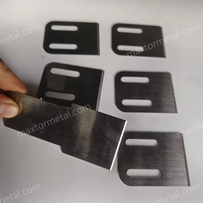
Selecting the right hot face pelletizing blades for air-cooled PE/PP isn’t just about material names on a quote. The right choice directly lowers tails and fines, stabilizes cut quality across shifts, and keeps uptime predictable so your total cost of ownership (TCO) tracks to plan. This guide shows you how to specify blade substrate, hardness, and coating; how to control geometry and tolerances for a clean cut; how to tune air-cooled operation; and how to manage lifecycle and sourcing for consistent, low-variance performance.
Use it three ways:
- Purchasing: build a tighter spec and acceptance checklist.
- Commissioning: align the cutter, validate the gap, and stabilize airflow.
- Maintenance: inspect, regrind, and document so your next order is right the first time.
Principais conclusões
How this guide was built (scope & verification): This article synthesizes OEM design concepts (alignment/controlled contact), common coated-component QA methods (e.g., XRF thickness checks, calotest thickness validation, and agreed adhesion screening/escalation tests), and shop-floor commissioning practices. Exact tolerances and setup values vary by cutterhead model and resin; treat any “example targets” as internal baselines and confirm final specs with your OEM manual and line trials.
- Prioritize clean, uniform contact at the die face; alignment and stable blade pressure reduce tails/fines fastest.
- Match substrate hardness and coating to resin and filler load; aim for edge toughness on recycled/filled streams.
- Control geometry: consistent edge angle, measured blade-to-die gap, and low runout are the backbone of a clean cut.
- Verify coatings with thickness and adhesion checks (XRF/calotest; scratch/tape as specified) to avoid early failure.
- In air-cooled setups, ensure directed, steady airflow across the die face and cutter path; synchronize cutter speed to haul-off.
- Treat blades as a managed asset: document regrind intervals, inspection results, and QC data to keep TCO predictable.
Selection fundamentals
Match resin and fillers
Resin behavior and contamination levels decide how hard and how tough your cutting edge should be. Virgin PE/PP often tolerates sharper edges and higher hardness. Recycled or mineral-filled formulations (CaCO3, talc, glass) drive abrasive wear and chip risk. For those, combine a tough substrate with a hard, low-friction PVD coating so the edge resists micro-chipping and smearing. Practical implication: don’t spec the same blade for washed film regrind and for virgin homopolymer PP; your fines and tails will tell on you.
Blade materials and hardness
Common substrate families include high-speed steels (e.g., M2) and cold-work tool steels (e.g., SKD11/D2). Many suppliers publish typical hardened ranges around the upper 50s to low 60s HRC for these grades, but the right target depends on heat treatment, resin contamination, and the die/cutter design. Higher hardness improves wear resistance, while sufficient core toughness reduces edge chipping during startup or when encountering contaminants. If you run abrasive fillers, pair a tough base with a suitable coating rather than simply pushing hardness higher.
For context on blade alignment and controlled contact principles used by OEM pelletizing systems (the alignment logic is transferable even when the cooling medium differs), see MAAG’s Gala design overview: MAAG Gala pelletizing systems — design principles.
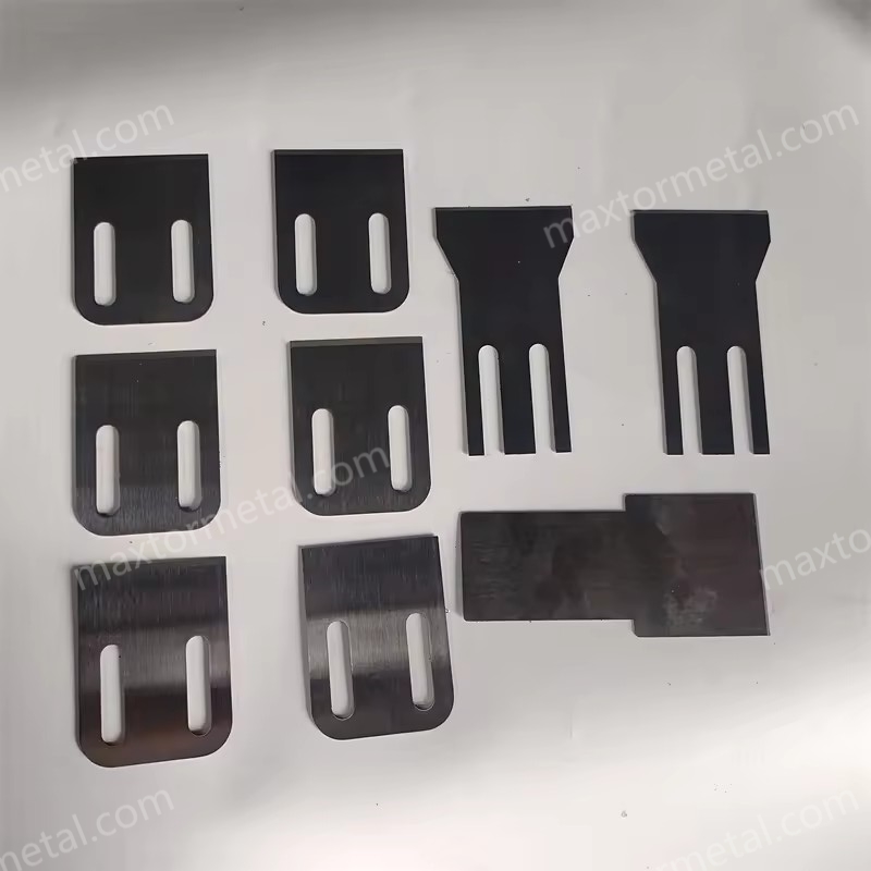
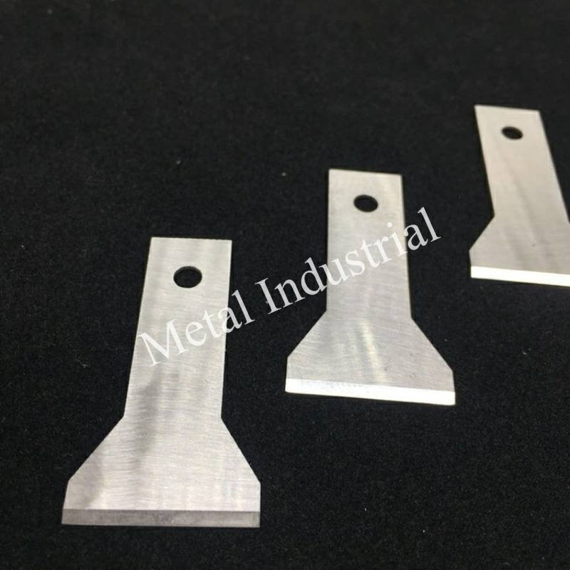
OEM fit and compatibility
Even the best blade fails when the fit is off. Before ordering, verify:
- Hub bolt pattern and hole spacing
- Blade OD/ID, thickness, and clamp features
- Cutterhead model, serial, and any OEM-specific chamfers/reliefs
Provide drawings/samples or exact OEM references. Ask the supplier to confirm dimensional tolerances and surface finish on contact faces so the blade seats flat and repeats position across sets. This is the fastest way to avoid vibration, noise, and irregular pellets after changeover.
Geometry and tolerances
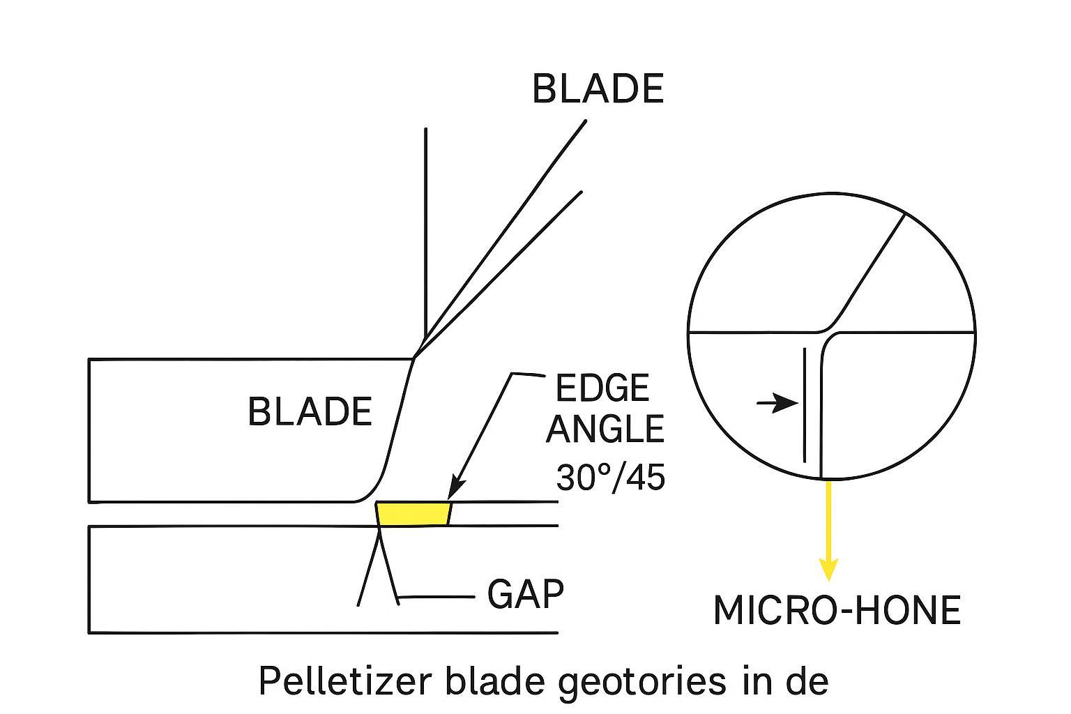
Edge angle and micro-hone
Edge angle sets the tradeoff between sharpness and durability. Market examples in pelletizer applications include 30° and 45° edges; your polymer’s stickiness and die geometry influence where you land. A small, controlled micro-hone (a tiny radius at the very edge) can stabilize the edge and reduce chipping without noticeably increasing fines. Treat the micro-hone as a defined feature, not an accident from hand deburring, and keep it consistent from blade to blade.
For examples of commercially referenced edge angles in pelletizer contexts, see Sollex’s application notes: Sollex pelletizer blade angles and product context.
Blade-to-die gap and alignment
There’s no universal number that works on every die and polymer, so use a commissioning workflow:
- Warm up to steady-state resin temperature and stabilize airflow.
- Establish uniform blade contact using your OEM’s procedure; verify at several clock positions.
- Incrementally adjust the blade-to-die clearance while sampling pellets (sieve for fines, visual for tails/stringers). Move in small, documented steps.
- Re-check after thermal stabilization and again after the first hour. If tails creep up, inspect for runoff, buildup, or chatter.
Why it works: stable, uniform contact and the smallest viable clearance reduce feathering and smear that cause tails. For the alignment logic and pressure control concept, see the OEM discussion referenced above: MAAG Gala cutter alignment concepts.
Flatness, parallelism, runout
Flat, parallel contact and low runout keep the edge tracking the die face evenly. Practical checks:
- Runout: dial indicator on the blade plane as the hub turns slowly; look for minimal variation and address hub wear or contamination if excessive.
- Flatness/parallelism: CMM or optical flat methods on the blade contact face and die face; remove contaminants and burrs.
- Contact pattern: bluing/ink checks during setup can confirm uniform seating.
These measurements prevent “wobble cuts,” intermittent tails, and localized fines. If your OEM publishes model-specific tolerances, follow those.
Example internal targets (verify with your OEM manual): Use these only as a starting point for incoming checks and trend tracking; the goal is repeatability on your specific cutterhead.
- Blade plane runout (assembled): set an internal target band (for example, “low hundredths of a millimeter”) and investigate any step-change versus your baseline after blade swaps.
- Contact face flatness / parallelism: define an internal acceptance band and measure the same way every time (same fixture, same points, same instrument).
- Gap uniformity: confirm the blade-to-die clearance is consistent at multiple clock positions after thermal soak; document the worst-point position.
Record results per blade set and hub so you can correlate geometry drift to fines/tails and avoid chasing process variables.
Coatings that work
Choose TiN, TiAlN, CrN, or DLC
Coatings extend edge life and reduce sticking—but only if thickness and adhesion are controlled. Here’s a quick comparison you can use during selection:
| Revestimento | Core strengths | Typical use on PE/PP |
|---|---|---|
| Estanho | Hard, wear-resistant; good general purpose | Virgin grades; moderate abrasion where low friction isn’t critical |
| TiAlN | Hot hardness and oxidation resistance | Higher temperature cuts or where heat tinting appears |
| CrN | Balanced wear + lower friction; corrosion resistance | Recycled or slightly sticky grades; helps limit smear |
| DLC (a‑C:H variants) | Very low friction; hard thin films | Sticky PE/PP; reduces buildup and helps edge glide |
Verification methods such as XRF for non-destructive thickness checks and calotest for destructive thickness validation are widely used in coating QA, as outlined by Oerlikon Balzers (QA overview in 2024–2025): Measurement techniques for coating QA (Oerlikon Balzers). A general acceptance workflow for coated components, including simple adhesion screening, is summarized in Oerlikon’s QA guide: Coated components QA and acceptance overview (Oerlikon).
How a supplier like MAXTOR integrates coating QC (neutral example): On incoming inspection, production teams can spot-check PVD thickness via XRF, log substrate hardness from heat treatment (e.g., typical hardened tool steel bands), and use tape/scratch methods as specified to screen adhesion. Internal process documentation and batch QC snapshots are commonly shared on request. For a technical primer on coated pelletizer knives from the brand, see the educational resource: MAXTOR METAL — PVD-coated pelletizer knives guide.
Coating thickness and adhesion
Treat coating QA as a routine, not an exception. A practical approach is to define what you will measure, where you will measure it, and what paperwork must ship with every lot:
- Thickness: perform XRF spot checks at defined locations on every batch; schedule periodic calotest validation cuts and archive micrographs when required.
- Adhesion: agree on the screening method (tape) and escalation test (scratch/indentation) in the PO; document results with batch/serial traceability.
- Records: capture substrate grade, heat treatment spec, measured hardness range, coating type, thickness means/ranges, and adhesion test notes per lot.
Incoming inspection checklist (copy/paste into your PO or IQC form):
- Identification & traceability: blade set ID/serial, lot number, coating batch, date, inspector.
- OEM fit: cutterhead model/serial; drawing revision used for the order.
- Dimensões: OD/ID, thickness, bolt pattern/hole spacing, countersink/counterbore details, keyways/chamfers (report actual vs. tolerance).
- Contact-face condition: surface finish requirement (if specified), burr-free edges, no rocking on a reference surface.
- Assembled geometry: blade plane runout and contact pattern check on the hub (document method + measurement points).
- Substrate & heat treatment: steel grade, heat-treatment certificate (if available), measured hardness results + test location(s).
- Revestimento: type, XRF thickness readings at defined locations (report mean/min/max), visual defects (pinholes/flaking).
- Adhesion: screening method (tape) result; escalation method (scratch/indentation) if required by spec.
- Embalagem: edge protection, corrosion protection, handling notes.
These steps prevent early edge failure and give you the data you need to correlate coating variation with fines or shortened runtime.
Deployment on recycled streams
Micro-case (measurement-first, no guessing): When you trial CrN vs. DLC on the same substrate for recycled PE/PP, set up a simple A/B log so decisions are based on your line’s data.
- Keep constant: resin recipe (filler %, melt index), die plate, cutterhead, airflow setting, and target pellet size.
- Track three KPIs: (1) fines % from the same sieve stack and sampling interval, (2) tails/stringers count per fixed sample mass, (3) runtime hours to first wipe-down and to scheduled regrind.
- Record QC alongside results: XRF thickness readings (mean/min/max), the adhesion screening method used, and the blade set ID.
After one or two stable runs per coating, you’ll usually see whether the limiting factor is abrasion (favoring tougher wear films) or smear/sticking (favoring lower-friction films).
Recycled PE/PP with fines, fillers, or occasional contaminants benefits from lower-friction films (CrN or DLC families) to reduce smear and sticking. Start with a tough substrate + CrN where abrasion dominates; if you still see smear buildup and tailing at steady state, trial DLC on the same substrate and compare runtime between regrinds and sieve-based fines percentage. Document both coating thickness (XRF) and adhesion screening so comparisons are apples-to-apples.
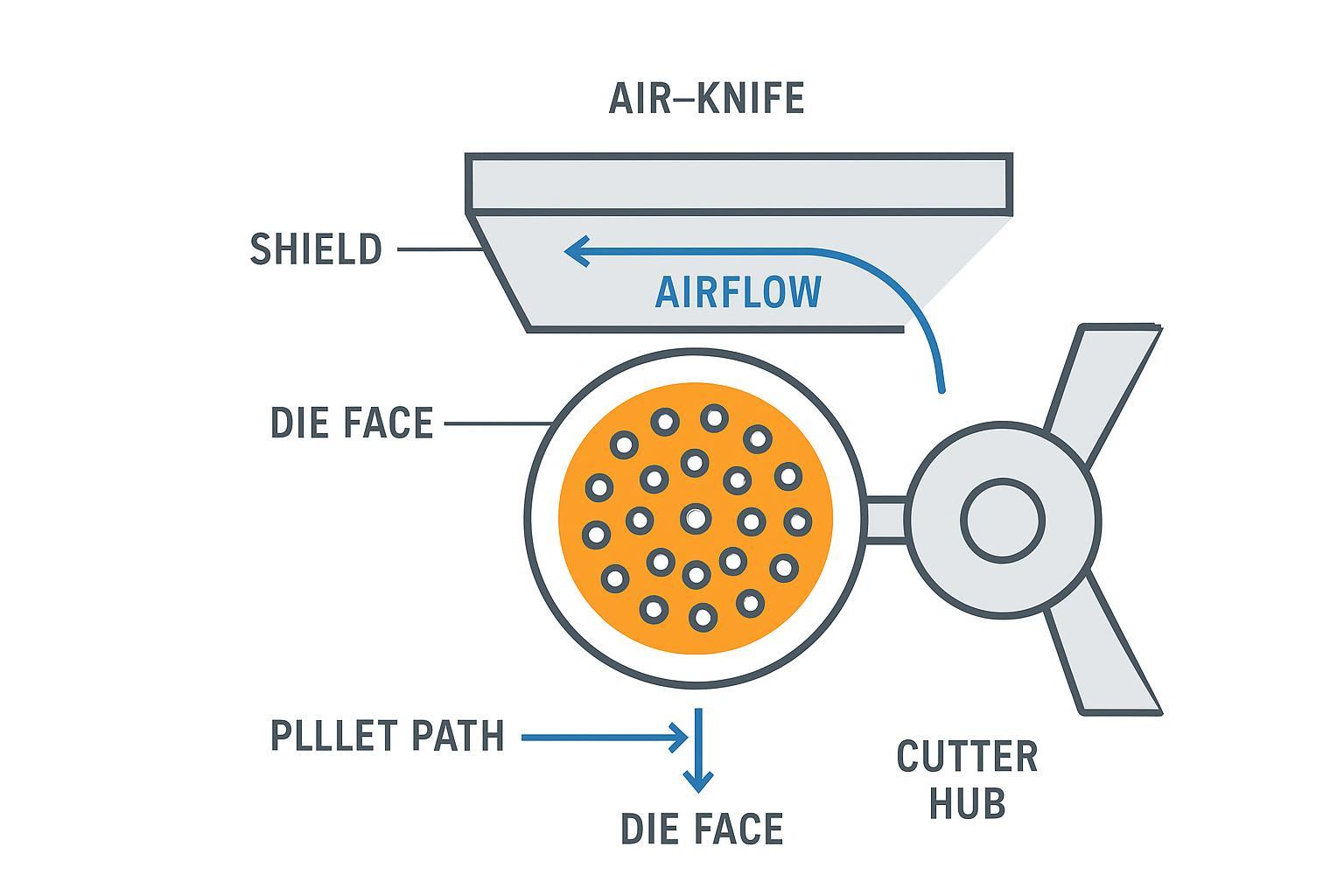
For context on airflow hardware positioning that informs how coatings interact with surface temperature and smear risk (strand pelletizer references; adapt the concepts), see MAAG’s brochures: MAAG PRIMO E — air-knife placement concepts (strand pelletizers).
Air-cooled operations
Strand temperature and airflow
Air assistance should stabilize the polymer surface before the blade arrives, then carry away heat from the cut. Practical signs you’re close: pellets separate cleanly with minimal smear; blade faces stay relatively clean between checks; no visible flutter at the die face. If you see stringers or smeared, comet-tail pellets, increase directed airflow across the die face and verify shielding to prevent turbulence from bouncing back into the cut zone. OEM manuals are the best source for model-specific air-knife positions and recommended ranges.
For a systems view of airflow placement concepts (strand equipment, but the airflow logic is transferable), consult MAAG’s technical brochures: MAAG PRIMO E — airflow placement concepts (strand equipment).
Cutter vs. haul-off sync
Clean cuts depend on synchronized line speed and blade strike frequency. If the cutter is slightly out of sync with haul-off, you’ll see periodic tails or thickness variation. Confirm encoder inputs, check for lag in speed control loops, and tune so the blade meets a stabilized strand at a consistent strike angle and timing.
Startup and changeover checks
- Confirm uniform blade contact and minimal runout after thermal soak.
- Inspect the die face for deposits; clean if any lip buildup is visible.
- Verify directed airflow across the die face and cutter path; adjust hood/knife alignment if flutter is observed.
- Sample pellets at 5 and 15 minutes; sieve for fines and inspect for tails/stringers; adjust clearance in small steps.
- Re-check coating and edge condition after the first hour; wipe away any early smear to prevent buildup.
Lifecycle and TCO
Regrind strategy and limits
Regrind before fines spike. Waiting until the edge is obviously dull increases the risk of tails, over-pressing the blade, and scuffing the die face. Build a trigger from your own KPIs: when sieve-based fines exceed your control limit at steady state or when runtime between wipe-downs shortens materially, schedule a regrind. Keep stock removal minimal and consistent across cycles so geometry stays repeatable. If chipping appears, reassess substrate toughness or micro-hone consistency before blaming coating thickness alone.
Inspection intervals and QC docs
Adopt a simple cadence:
- Shift/daily: Visual check for nicks, burrs, smear; wipe blade face; verify contact and sound.
- Weekly: Inspect runout and fasteners; record pellet sieve data and any tails incidence.
- Lot change or monthly: XRF thickness spot-check on coated blades; adhesion screen as specified; log substrate hardness and any heat-treatment certifications.
Tie these records to blade serials and production lots. Over a quarter, you’ll see which combinations of substrate, coating, and operating window produce the best fines/tails profile on your resin mix.
Sourcing economics and spares
Treat blades as a rotating asset pool. Maintain enough spare sets to cover regrind turnarounds and incoming QC window without jeopardizing uptime. In contracts, specify dimensional tolerances, substrate grade and hardness, coating type, and QA documentation required on each lot. Price is one line item; predictable quality and documented QC are how you avoid paying twice in downtime.
Conclusão
Before you order, specify the substrate and hardness suitable for your resin/filler mix, choose a coating based on wear vs. sticking risk, and define acceptance tests for thickness and adhesion. During commissioning, stabilize airflow, set uniform blade contact, and tune the blade-to-die gap stepwise with pellet feedback to minimize tails and fines in air-cooled PE/PP. Manage regrind timing and QC documentation so your TCO stays predictable and uptime remains high.
If you need a neutral technical reference or to discuss QC practices for coated pelletizer knives, visit the brand homepage: MAXTOR METAL.
About the team behind this guide: MAXTOR METAL has 15+ years of experience manufacturing custom, precision-ground industrial blades. For pelletizing knife orders, teams typically control repeatability through documented material/heat-treatment records, in-process dimensional checks, and coating QA logs (for example, XRF spot checks for thickness) so users can tie incoming inspection results back to a specific lot.