

By Tommy Tang (Senior Sales Engineer, Nanjing METAL Industrial). 12 years in slitting & industrial cutting applications. Certifications: CSE, CME, Six Sigma Green Belt, PMP.
Introdução
Glass fiber–reinforced polymers (GFRP) are unforgiving on cutting edges. Hard, silica-based fibers abrade the knife, rounding the edge and seeding micro‑chips that show up as tails and later break into fines. As fines rise, dryers clog faster, operators chase quality drift, and unplanned stoppages creep in. The net effect: shortened runtime between regrinds and replacements.
Tungsten carbide inlaid rotary cutters counter this with a wear‑stable WC–Co tip bonded to a tougher steel body. The carbide inlay resists abrasive rounding far better than HSS, while the steel backing absorbs impact events common on strand/traction pelletizers. When paired with disciplined setup and resharpen SOPs, plants typically see longer continuous runs, steadier pellet shape, and fewer emergency stops.
What you’ll learn here: how to choose the right inlaid cutter for GFRP duty, field‑tested operating practices (gap, alignment, geometry, grade), the QA documents to request, and the KPIs/TCO model to validate gains on your line.
Principais conclusões
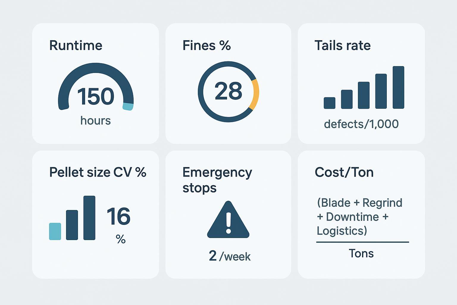
- Hero KPI: maximize mean runtime between scheduled regrinds/replacements; use fines% and tails rate as early‑warning indicators.
- Tungsten carbide inlaid rotary cutters maintain a sharper effective edge in abrasive service, while the steel body mitigates chipping risk vs. solid carbide.
- For strand pelletizers, control knife‑to‑die gap within a tight window (~0.03–0.08 mm; confirm per OEM) and verify rotor runout/seat flatness to stabilize cuts.
- Match WC–Co grade and micro‑geometry (hone/chamfer) to fiber load and impact risk; set resharpen thresholds tied to fines% delta and edge radius.
- Standardize procurement: dimensional tolerances, hardness targets, CMM and hardness records, and full traceability; plan a 4–8 week A/B pilot and compute cost/ton.
Why Tungsten Carbide Inlaid Rotary Cutters
Abrasive wear vs HSS and solid carbide
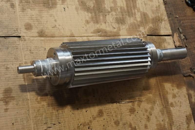
HSS loses its edge quickly in GFRP as glass fibers plow and micro‑abrade the cutting radius, accelerating tails and fines. Solid carbide holds hardness but is brittle; a strand snap or rethread bump can chip corners, forcing premature changeouts. Inlaid carbide places a high‑hardness WC–Co tip at the wear zone and supports it with a tough steel body, combining wear life with impact tolerance. General cutting literature reports substantially longer life for carbide‑tipped vs HSS in abrasive media, consistent with shop‑floor experience in plastics converting; see mechanism context in the 2018 brief from American Cutting Edge and a 2025 explainer on HSS vs TCT vs PCD in cutting tools for why carbide tips retain sharpness better in abrasive duty (American Cutting Edge overview, 2018).
Additionally, erosive studies show glass fibers produce significant wear compared with some carbon fiber systems, reinforcing the abrasive‑duty premise (Mendoza et al., 2021).
Inlay construction: wear edge, tough body
A brazed inlay concentrates extremely hard WC–Co at the cutting line (typical HRA ~90–94; ≈1400–1800 HV) while the backing steel is heat‑treated for support and shock resistance (commonly HRC mid‑40s to upper‑50s depending on geometry and regrind allowance). Submicron WC grades improve edge retention; slightly higher Co content can trade a bit of hardness for toughness on impact‑prone lines. See materials libraries for hardness ranges and grade behaviors (e.g., Hyperion materials resources, accessed 2025–2026: Hyperion materials library). For pelletizer‑specific values, validate with your supplier’s QA.
Expected gains: runtime, fines, cost/ton
Mechanistically, a more wear‑stable edge maintains a clean shear plane longer. That reduces tails that later fragment into fines, cuts down dryer/filter cleanouts, and extends mean runtime—the hero KPI. Secondary effects typically include steadier pellet size CV% and a lower emergency‑stop rate. Because downtime drives cost, improving runtime often yields a favorable cost/ton even if blade unit cost rises. Public, pelletizer‑specific multipliers are scarce; treat improvements as hypotheses to test via the trial plan below. Troubleshooting guides tie tails/fines directly to cut quality, supporting this linkage (Plastics Technology underwater pelletizing troubleshooting, 2020).
Operating Practices for Clean Cuts
Knife-to-die gap and alignment
For strand pelletizers, start by blue‑checking or lightly contacting the die face, then back off to a small, uniform clearance. Typical practitioner windows are about 0.03–0.08 mm with control tolerance around ±0.02–0.05 mm; confirm exact setpoints and methods per your OEM manual. Verify rotor runout with a dial indicator at the cutting circle; aim for low TIR and adjust eccentric mechanisms evenly. Uneven gap shows up first as localized tails and fines spikes. Field troubleshooting consistently links improper gap to pellet defects (Plastics Technology, 2015).
Convert these quick checks into SOP steps: measure seat flatness across the knife contact area to prevent rocking; torque fasteners in sequence; recheck gap hot vs. cold to account for thermal growth; and after the first minutes of run‑in, re‑verify contact marks and back‑off evenly.
Edge geometry and carbide grade match
Match geometry to fiber content and impact risk. For high glass loadings (e.g., 20–50% GF), a submicron WC–Co grade with a small edge hone or micro‑chamfer reduces micro‑chipping while maintaining sharpness. On lines with frequent strand breaks or rethread bumps, consider a slightly tougher grade (higher Co) and a conservative micro‑chamfer to blunt peak stresses. Keep rake and relief angles within OEM norms; extreme sharpness without a hone can chip prematurely in GFRP.
Process stability and resharpen thresholds
Tie maintenance to data, not guesswork. Two practical triggers:
- Fines% rises >20% vs. your stable baseline (same polymer, same throughput);
- Edge radius growth approaches ~0.2 mm on magnified inspection or profilometry. Both indicate the shear plane is degrading. Because tails become fines with handling and drying, react before tails proliferate (Plastics Technology troubleshooting, 2020). Standardize the inspection interval (e.g., every 2–4 hours initially, then extend as data stabilize).
Selection & Compatibility

Match resin, fiber content, impact risk
Think in terms of abrasion vs. shock. High GF content and mineral‑filled blends call for harder, finer‑grain WC inlays and reinforced micro‑geometry. If your line sees frequent strand snaps, prioritize toughness (slightly higher Co) and consider geometry that diffuses impact (micro‑chamfer). For cleaner, lower‑fill resins, sharper edges with minimal hone can improve surface finish.
Tolerances, flatness, runout for OEMs
OEM brochures emphasize precise, often toolless gap adjustment but rarely publish numeric limits. In practice, maintenance teams target low rotor TIR at the cutting circle and tight seat flatness to keep the gap uniform. As pragmatic starting points used in precision cutting work (always confirm the exact method and acceptance limits in your OEM manual/service documentation):
- Rotor runout: strive for ≤0.05–0.10 mm TIR at the cutting circle;
- Knife seat flatness: ≤0.02–0.05 mm across the contact area.
These are typical practice ranges to validate per model; OEM literature often describes adjustment mechanisms without publishing numeric limits publicly (see MAAG’s T‑Series strand pelletizer overview (MAAG, 2019), the Scheer S3500 brochure (MAAG, 2019)e o Coperion SP EN/PURE brochure (Coperion, 2018)).
Revestimentos e quando eles ajudam
Os revestimentos PVD podem retardar ainda mais o desgaste abrasivo e reduzir a adesão. Opções práticas:
- TiN/TiAlN para robustez térmica em temperaturas de granulação mais elevadas;
- Revestimentos do tipo DLC para comportamento de baixa temperatura e baixa adesão. Os fornecedores documentam que revestimentos compatíveis aumentam a vida útil do gume em regimes abrasivos/adesivos; escolha com base na janela de temperatura e na química da resina (Visão geral do revestimento DURIT; consulte também as orientações gerais sobre a seleção de revestimentos para lâminas de corte longitudinal da American Cutting Edge, período de 2018 a 2020).
Procurement & Documentation
É aqui que muitos programas falham ou decolam. Defina as especificações e a rastreabilidade logo no início e, em seguida, valide no recebimento.
Exemplo neutro de integração de capacidade do fornecedor: Alguns fabricantes de facas personalizadas para granuladores podem produzir cortadores rotativos com insertos de carboneto de tungstênio conforme desenho e fornecer artefatos de garantia de qualidade (QA), como relatórios dimensionais de CMM, notas de tratamento térmico e registros de dureza. Por exemplo, a MAXTOR METAL oferece lâminas industriais personalizadas com opções de pontas de metal duro e compartilha insights de processo sobre tratamento térmico e seleção de materiais (Fonte da Base de Conhecimento). Consulte a visão geral dos produtos e o guia de tratamento térmico para contextualização: Produtos MAXTOR METAL e guia de tratamento térmico de lâminas de cisalhamento rotativas. Solicite documentos específicos de QA com qualquer pedido; não confie apenas em visões gerais da web.
Checklist de especificações: dimensões, dureza, materiais
- Desenho com todas as dimensões e tolerâncias críticas (GD&T onde necessário);
- Classe do inserto (WC–Co) e faixa de dureza nominal (ex.: HRA e/ou HV), classe de grão (submícron/mícron);
- Classe do aço de suporte e dureza alvo (faixa de HRC) com tolerância de reafiação por altura da ponta;
- Especificação da geometria do gume (tamanho do arredondamento ou microchanfro), ângulos de folga/ataque;
- Tipo de revestimento e espessura, se aplicado;
- Critérios de balanceamento/excentricidade (runout) se o conjunto do rotor estiver incluído.
Registros de qualidade: CMM, dureza, rastreabilidade
- Relatório de CMM listando todas as dimensões críticas e resultados de planeza/excentricidade;
- Registros de dureza: Vickers para a ponta de metal duro, Rockwell C para o suporte (observe que as conversões HV↔HRC são aproximadas e dependem do método);
- Certificado de tratamento térmico com números de lote/corrida; rastreabilidade total do lote que vincula as lâminas aos certificados de material e resultados de inspeção.
Exemplo de microfluxo de trabalho: Na inspeção do primeiro artigo (FAI), realize as verificações abaixo antes da instalação. Um fornecedor que possa agrupar esses documentos como um pacote FAI (revisão do desenho, CMM, dureza, registro de tratamento térmico) reduzirá seu ciclo de aceitação.
| Item de verificação FAI | How to measure | Critério de aprovação | Registro a manter |
|---|---|---|---|
| Altura da ponta e saliência vs. assento | Paquímetro/micrômetro; comparar com o desenho e a referência do assento | Dentro da tolerância do desenho; consistente em todas as facas | Folha de FAI + foto da configuração de medição |
| Planeza e retilineidade do assento | Desempeno de granito + calibrador de folga ou planeza por CMM; inspecionar quanto a oscilações | Dentro da tolerância de planeza; sem oscilação no assento | Relatório de CMM ou registro de planeza |
| Dureza dentro da faixa especificada | HV para a ponta de metal duro; HRC para o aço de suporte (mesmo método para cada lote) | Atende à faixa especificada para a ponta e o suporte | Relatório de dureza + certificado de tratamento térmico (nº do lote/corrida) |
Logística: prazo de entrega (lead time), embalagem, importação
- Confirme os prazos de fabricação e trânsito com margens de segurança para ciclos de reafiação;
- Embalagem que proteja as pontas frágeis (protetores de gume, espuma, papel VCI, dessecantes), com etiquetas de manuseio;
- Para importações, certifique-se de que os códigos HS, a precisão da fatura comercial e quaisquer acordos de IVA estejam claros; solicite fotos da embalagem antes do envio.
KPIs & TCO Model
Qualidade do grânulo: finos, caudas, CV%
Monitore os defeitos dos grânulos como indicadores antecedentes. Defina a porcentagem de finos (fines%) por peso após a secagem ou por meio de filtragem de água de circuito fechado; padronize o tamanho da amostra e o tempo. Registre a ocorrência de caudas por 1.000 grânulos com uma verificação visual simples ou ampliada. Calcule o CV% do tamanho do grânulo (diâmetro ou massa) para quantificar a estabilidade. A Plastics Technology oferece taxonomias práticas de defeitos e orientações de amostragem (artigo especial sobre a perfeição do grânulo, 2023).
Tempo de atividade (uptime): tempo médio de operação, paradas de emergência
Defina o KPI principal: tempo médio de operação entre reafiados/substituições programadas. Registre os tempos de início/parada e as causas; separe as paradas de emergência das trocas planejadas. Busque prolongar o tempo de operação mantendo os limites de qualidade estáveis. Use um painel (dashboard) para que a manutenção, a produção e as compras compartilhem a mesma visão (visão geral de práticas de dashboard, 2018).
Calculadora de custo/tonelada e plano de teste
Para tornar seu piloto de 4 a 8 semanas reproduzível (e evitar discussões baseadas em “achismos”), use uma planilha simples de captura de dados como esta em cada lote:
| Campo | How to capture | Notas |
|---|---|---|
| Resin / GF% / additives | Batch sheet or COA | Keep formulation constant for A/B |
| Pelletizer type & model | Nameplate / maintenance record | Strand vs underwater; rotor diameter matters |
| Knife set ID + drawing rev | Label + receiving docs | Tie to CMM/hardness records |
| Knife-to-die gap setpoint | Feeler/shim method per OEM | Record cold + hot if you adjust |
| Rotor TIR at cutting circle | Dial indicator | Record pre-run and after first run-in |
| Start/stop timestamps | Line log / MES | Separate planned vs emergency stops |
| Hero KPI: runtime per edge (hours) | Stop time minus start time | Define “edge” consistently (per knife set) |
| Changeover time (minutes) | Stopwatch | Include cleanout time if it’s driven by fines |
| Fines% sampling method | Standard sample mass + sieve/filtration + dry weight | Same sample location and interval |
| Tails rate | Count per N pellets under consistent lighting/magnification | Define “tail” threshold (length) |
| Throughput (kg/h) & total tons | Line report | Needed for cost/ton |
| Resharpen trigger met? | Yes/No + reason | Fines% delta, edge radius, visual chips |
If you keep this sheet consistent across 2–3 cycles, the runtime delta and cost/ton model become much more defensible to production and purchasing.
A simple, transparent calculator keeps teams aligned:
cost/ton = (blade cost + regrind cost + downtime cost + logistics) / tons produced over the blade’s service life.
Inputs to document:
- Blade unit price and expected regrinds per inlay height;
- Average runtime hours per edge until resharpen, at constant resin/throughput;
- Downtime cost/hour (labor + lost margin) and average change time;
- Logistics and inventory carrying costs.
4–8 week pilot plan:
- Baseline with incumbent knives on matched runs; capture runtime, fines%, tails, emergency stops.
- Install tungsten carbide inlaid rotary cutters with documented grade/geometry; verify gap, alignment, and QA docs on receipt.
- Run to predefined resharpen triggers (fines% delta or edge radius); collect KPIs and notes on operator interventions.
- Compute runtime delta (hero KPI) and model cost/ton with sensitivity bands (optimistic/typical/conservative on downtime cost and runtime).
- Decide on standardization after 2–3 cycles to average variability.
Conclusão
Tungsten carbide inlaid rotary cutters align well with the abrasive reality of GFRP. By pairing a hard, wear‑stable tip with a tough body—and by dialing in knife‑to‑die gap, alignment, and micro‑geometry—you can extend mean runtime, stabilize pellet quality, and lower cost/ton. The rest is discipline: lock specs and QA, watch fines% and tails as leading indicators, and run a tight resharpen cadence.
Next steps: pick one strand line, run the 4–8 week pilot with clear QA docs and KPIs, and schedule a review to confirm runtime gains and standardize what works.

 English
  Spanish
  Italian
  French
  Portuguese
  Russian
  German
  Arabic
  Hindi
Hindi  Vietnamese
  Indonesian
  Japanese
  Korean