Rotary cutter tooth count (how many knives/teeth are on the rotor) is one of the fastest levers you have for stabilising pellet length on a strand pelletiser — and it’s the cleanest way to stay within a realistic cutter RPM ceiling. Get it wrong and you’ll see it immediately: long/short variation, tails, more fines, and a higher chance of nuisance trips because the cutting station is working outside its stable window.
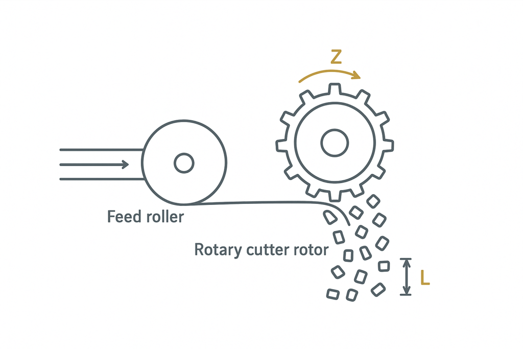
The link is pure kinematics. Pellet length is set by how far the strand advances between cuts, and the cut frequency is set by cutter RPM multiplied by tooth count. As MAXTOR METAL summarises in its rotary-cutter guide, pellet length scales with the ratio of feed speed to cutter RPM and knife count.
You usually adjust tooth count when your process pushes you to extremes: higher line speed, smaller pellets, or a hard RPM ceiling. Abrasive, high-fill, and recycled materials also tend to move the “stable” window because you’ll trade off clean shear against wear, micro-chipping, and heat build-up at the edge.
The good news is you can validate a tooth-count choice quickly on the machine with a few simple checks: measure actual pellet length, watch fines/tails trends at constant settings, and confirm that clearance and runout aren’t undermining the math.
Scope & assumptions (for reproducibility): The relationships below assume the true strand speed at the cutter (V) is known (no significant slip at feed rolls), the knife/bed-knife geometry is stable, and the goal is to control pellet length distribution (not just an average). Always verify against your specific pelletizer OEM manual and safety procedures.
The kinematic link
Core formula and units
Define the variables:
- V = strand line speed at the cutter (m/min)
- L = target pellet length (mm)
- n = cutter rotor speed (rpm)
- Z = tooth count (teeth/knives on the rotor)
Cuts per minute is:
- f = n · Z (cuts/min)
Pellet length is the distance advanced per cut:
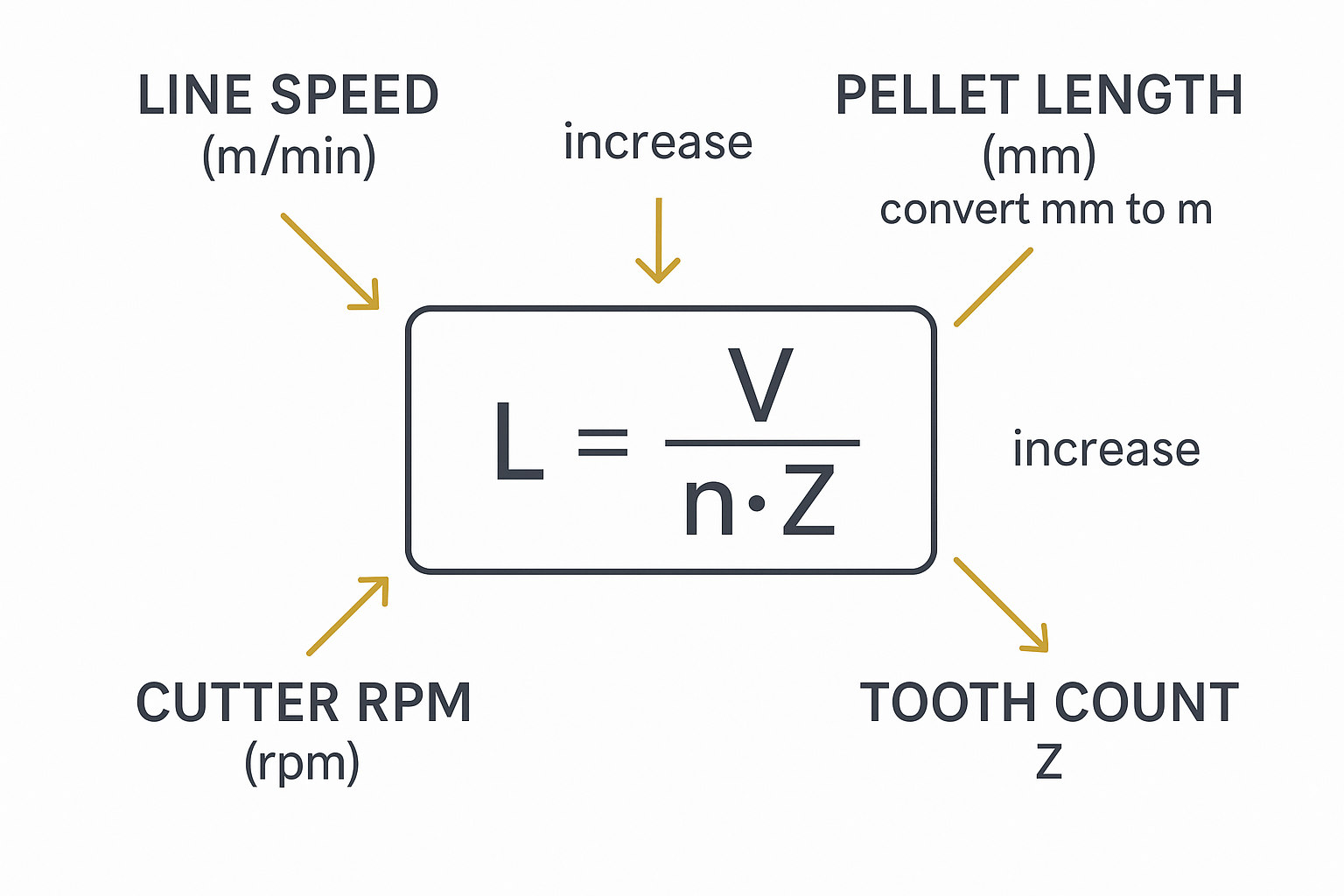
- L(m) = V / (n · Z)
To use L in mm, convert: L(mm) = 1000 · V / (n · Z).
Điểm chính: If V is fixed, you can make pellets shorter only by increasing cutter RPM (n), increasing tooth count (Z), or both.
Variable interactions
The interactions are linear and predictable:
- Increase V → pellets get longer (unless you increase n or Z to compensate).
- Increase n → pellets get shorter (until you hit vibration/noise, thermal issues, or the drive limit).
- Increase Z → pellets get shorter at the same n (often the cleanest way to reduce required RPM).
Two practical notes matter in real lines:
- “V at the cutter” is the truth. If strands slip at the feed rolls or are pulled by downstream drag, your measured pellet length won’t match the calculation.
- Mechanical scatter dominates when you get too aggressive. Once n is high enough, any runout, clearance variation, or strand wandering shows up as length variation and fines.
Worked example
Use a common production default and keep it metric:
- Line speed V = 40 m/min (within the commonly specified 20–80 m/min range)
- Target pellet length L = 3 mm (a common default target)
A vendor spec that reflects this typical window is the Techlab Systems “Pelletizing Systems” guide (20–80 m/min; 1–6 mm).
First convert L to meters:
- L = 3 mm = 0.003 m
Compute required cuts per minute:
- f = V / L = 40 / 0.003 ≈ 13,333 cuts/min
Now translate that into RPM for a few common tooth counts:
- If Z = 12 → n = f / Z ≈ 13,333 / 12 ≈ 1,111 rpm
- If Z = 24 → n ≈ 556 rpm
- If Z = 30 → n ≈ 444 rpm
The point isn’t that you “should run” those RPMs; it’s that tooth count is what brings the required RPM back inside your machine’s stable operating window.
Quick sizing table (copy/paste)
Use this as a fast check before you change hardware. Compute:
- n_req (rpm) = 1000 · V(m/min) / (L(mm) · Z)
| V (m/min) | L (mm) | Z (teeth) | n_req (rpm) |
|---|---|---|---|
| 40 | 3 | 12 | 1,111 |
| 40 | 3 | 24 | 556 |
| 40 | 3 | 30 | 444 |
If your n_req is too close to your practical ceiling, increase Z (if available) to regain stability margin before pushing RPM.
Field example (anonymized, qualitative)
In day-to-day support, a common pattern is that pushing line speed without rebalancing cut frequency forces rotor RPM toward the unstable end of the machine’s range. In those cases, moving to a higher tooth count (Z) to bring RPM back down typically improves length consistency (tighter distribution), reduces tails/longs, and lowers fines—provided knife condition, clearance, and strand cooling are kept consistent.
Selection workflow
Define inputs
Lock the inputs before you touch hardware:
- V (m/min): measure or confirm actual line speed at the cutter, not just extruder RPM.
- L (mm): define what “pellet length” means for your QA (average length, max length, or distribution).
- n_max (rpm): the practical rotor RPM ceiling for your pelletiser (drive limit and stability limit).
- Available Z: what tooth counts you can actually install (rotor design, inserted blades, knife pockets).
If you’re running recycled or high-fill materials, also treat these as “inputs” because they shrink the stable window:
- Abrasiveness / filler level (wear and micro-chipping risk)
- Strand temperature at entry (smear vs brittle fracture)
- Strand count and strand diameter consistency
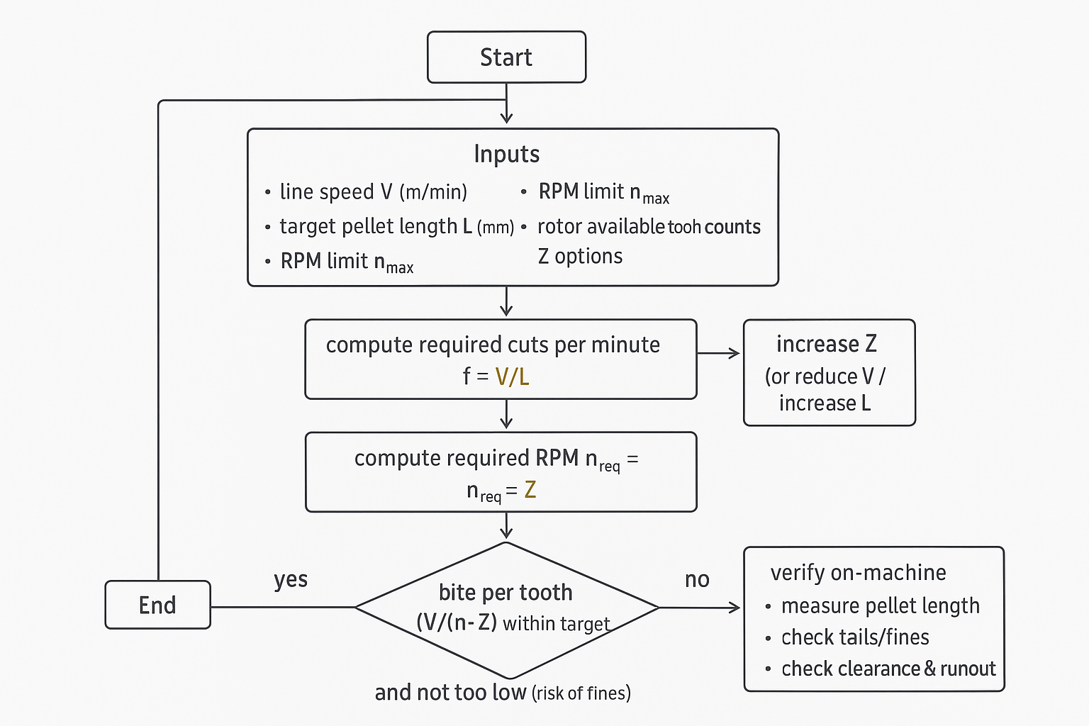
Select rotary cutter tooth count
- Compute the required cut frequency:
- f = (V / L(m)) cuts/min
- For each available tooth count Z, compute the required rotor speed:
- n_req = f / Z rpm
- Choose the smallest Z that keeps n_req comfortably below your practical ceiling.
Why “comfortably”? Because you need margin for normal variation: line speed drift, strand swell, and gradual wear that increases cutting force.
If no available Z puts you below the RPM ceiling, you only have three real options:
- reduce V (throughput hit)
- increase L (pellet spec change)
- change rotor hardware (different tooth count range)
Verify RPM and bite per tooth
Even when n_req is acceptable, you still need a rationality check on “bite per tooth” — the strand advance per cut. In this context it’s the same value you are targeting (pellet length), but it’s useful to treat it as a stability variable:
- Very small bite (very high cut frequency) can raise fines and heat if clearance or edge condition isn’t controlled.
- Very large bite (low cut frequency) can raise tails and “squeeze” deformation, especially on soft or warm strands.
Do three on-machine checks before you declare success:
- Length check: collect 50–100 pellets after conditions stabilise. Define your QA statistic (e.g., mean + standard deviation, or P90/P95 length) and measure with a consistent method (calipers or optical measurement).
- Fines/tails check: trend fines as a mass % using a consistent screen/sieve cut (or your plant’s standard) and count tails/longs at constant V, n, Z.
- Mechanics check: confirm knife-to-bed clearance and rotor runout are within your machine’s capability; if you can’t hold them, the calculation won’t hold either.
Neutral references (for further reading): Bay Plastics Machinery explains strand pelletizer setup and the relationship between feed speed, cutter speed, and pellet length in “Basics of Strand Pelletizing” (BPM Training PDF). MAAG Group provides OEM documentation on strand pelletizing systems, strand draw-in, and cutting station fundamentals in “JSG — Automatic Dry Cut strand pelletizing system” (MAAG PDF) Và “M-ASG — Strand pelletizing system” (MAAG PDF).
Trial log template (copy/paste)
Use a simple one-line log per trial so you can compare changes over time.
| Ngày | Material / filler | Strands (count) | V (m/min) | L target (mm) | Z (teeth) | n (rpm) | Clearance setting | Runout check | Sample size | Length stat (mean+SD or P95) | Fines method | Fines (%) | Tails/longs count | Ghi chú |
|---|---|---|---|---|---|---|---|---|---|---|---|---|---|---|
Tip: keep the sampling point and measurement method identical for every trial; otherwise the “improvement” may just be measurement noise.
Constraints and materials
Overlap and clearance
Tooth count can’t compensate for a cutting station that is geometrically unstable.
If clearance varies across the bed knife, you’ll see a “mixed mode” cut: some strands shear cleanly, others tear or smear, so pellet length scatter increases even when the setpoints are steady. In abrasive duty, the problem is amplified because edge wear increases clearance sensitivity.
MAXTOR METAL documents PM tool steel (HRC 60–63), micro‑hone 0.005–0.02 mm, Ra <0.2 µm, and run‑out/parallelism checks ≤0.02–0.05 mm.
See the high‑filler note.
Dynamics and strand count
Tooth count changes the cutting frequency. As frequency rises, dynamic effects matter more:
- More strands means more opportunities for one strand to wander, stick, or arrive hotter/softer than the rest.
- If strand count is high and cooling is uneven, the cutter sees a mix of “easy” and “hard” cuts, which can excite vibration and show up as length variation.
- At higher frequency, any eccentricity/runout becomes a length modulator: every revolution repeats the same error pattern.
Operationally, the fastest way to detect a dynamics problem is to hold V and n constant and watch whether pellet length scatter correlates with rotor position (periodic) or with strand events (random).
Knife materials and tolerances
Abrasive and recycled materials usually force a compromise: you want a robust edge that resists micro-chipping, but you also need tight geometry so the cut stays a shear, not a tear.
For procurement and QC discussions, it’s useful to frame tolerance as “system-appropriate,” not “as tight as possible.” MAXTOR METAL’s industrial blade tolerance guide gives example tolerance bands and inspection notes that can help you specify what you actually need (and verify it on receipt).
A neutral, practical supplier check is to request: material certificate, heat-treatment report, hardness scan, and a dimensional/flatness report aligned to your machine’s bed-knife and rotor interface.
Phần kết luận
Choosing rotary cutter tooth count is a controlled trade between kinematics (hit the pellet length) and stability (stay inside your RPM and mechanical limits). Start with the math, then pick the smallest Z that keeps required RPM out of the red zone — and leave margin for drift and wear.
To stabilise pellet size and reduce fines, validate on the machine with simple checks: measure pellet length distribution, trend tails/fines at fixed settings, and confirm clearance/runout are good enough for the calculation to be meaningful.
For abrasive/high-fill and recycled materials, expect the stable window to narrow. You’ll typically bias toward more robust knife materials and tighter, verifiable geometry, then re-tune Z and n to keep the cut clean without pushing RPM into a vibration or heat problem.
If you need a documented reference point for knife materials and measurable geometry targets in abrasive duty, KIM LOẠI MAXTOR publishes practical notes you can use as a checklist when you’re qualifying any supplier.
Author: Tommy Tang, Senior Sales Engineer, Nanjing METAL Industrial — 12 years in industrial blades & pelletizing applications. Certifications: CSE, CME, Six Sigma Green Belt, PMP.
Reviewed by: MAXTOR METAL Engineering Team. Learn more: https://maxtormetal.com/about/