

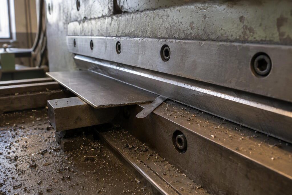
Tóm tắt nhanh: Khe hở lưỡi dao cắt tấm được đặt ở mức 5–10% độ dày vật liệu, được đo tại điểm cắt. Đối với thép mềm dày 6 mm, con số này tương đương với khe hở 0,30–0,60 mm — nhưng tỷ lệ phần trăm đó chỉ là khoảng giá trị bắt đầu, không phải là kết quả cố định. Hãy xác nhận giá trị vận hành thực tế bằng một đường cắt thử trên vật liệu thực tế của bạn, kiểm tra khe hở tại ba điểm dọc theo chiều dài lưỡi dao bằng thước lá (feeler gauge), và coi bất kỳ chiều cao bavia nào vượt quá 5% độ dày là dấu hiệu kích hoạt để kiểm tra lại khe hở.
Ghi chú kỹ thuật: Khe hở lưỡi dao cắt tấm là khoảng cách vuông góc giữa mép cắt trên và mép cắt dưới, được thể hiện bằng tỷ lệ phần trăm độ dày vật liệu. Nó chi phối tỷ lệ giữa vùng bóng và vùng gãy trên mép cắt, chiều cao bavia và tải trọng tác dụng lên dao cho mỗi hành trình cắt. Quy trình thiết lập và kiểm soát chất lượng (QC) của Maxtor Metal coi khe hở là một thông số quy trình đặc thù theo vật liệu — chứ không phải là một cài đặt cố định trên máy — và lập tài liệu cho từng đơn hàng cùng với tình trạng lưỡi dao và thông số bán kính mép cắt.[→ See Maxtor Metal shear blade specifications and material options]
Khe hở lưỡi dao cắt tấm là khoảng cách nằm ngang giữa mép dao trên và mép dao dưới tại điểm cắt, và trên máy cắt đột dập/máy cắt guillotine, nó thường được cài đặt theo tỷ lệ phần trăm độ dày vật liệu thay vì một con số cố định. Việc cài đặt sai sẽ dẫn đến thiệt hại chi phí rất thực tế: phế liệu dải cắt do chất lượng mép cắt kém chiếm từ 5% đến 10% tổng chi phí sở hữu — một con số tích tụ và tăng lên qua mỗi chu kỳ mài lại dao.
The 5–10 percent rule is a starting range rather than a specification. Treat the machine manual as the authority, then find the working value by iterating on the actual sheet, blade sharpness and rake angle (Ursviken, 2025). Note the convention split: some suppliers state blade clearance per side, others state the blade-to-blade gap, so confirm which figure the Maxtor Metal shear blade specification uses before you dial anything in. Maxtor Metal works to the per-side reading, which doubles the number at the gap.
Những điểm chính
- Khe hở lưỡi dao cắt tấm là một tỷ lệ phần trăm độ dày vật liệu, được cài đặt tại điểm cắt.
- Khoảng 5–10% là phạm vi bắt đầu; sổ tay hướng dẫn của máy sẽ quy định giá trị cuối cùng.
- Hãy xác nhận xem một số liệu được công bố là khe hở lưỡi dao trên mỗi bên hay tổng khe hở giữa hai lưỡi dao.
- Chất lượng mép cắt kém là nguyên nhân gia tăng 5%–10% tổng chi phí sở hữu do tạo ra phế liệu dải cắt.
Ghi chú về nguồn tài liệu: Cẩm nang này được xây dựng dựa trên các tài liệu tham khảo đã xuất bản về kỹ thuật cắt tấm — Hướng dẫn AHSS, tài liệu quy trình cắt của ispatguru, và hướng dẫn từ các nhà chế tạo thiết bị như Ursviken và Sureay — cùng với kinh nghiệm thực tế tại xưởng sản xuất của Maxtor Metal. Khi một số liệu đến từ nguồn độc lập, nó sẽ được trích dẫn rõ ràng; khi nó phản ánh giới hạn nghiệm thu nội bộ của nhà sản xuất, điều đó được ghi rõ để bạn có thể cân nhắc phù hợp.
Cơ chế mép cắt
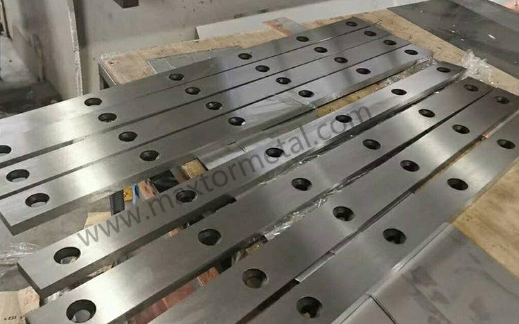
Shear blade clearance decides how a cut fails, and that failure is what produces either a clean edge or a burr. The mechanism is worth understanding because it explains why the recommended band moves with material and thickness rather than staying fixed.
In short: clearance controls the split between smooth burnish and rough fracture on the cut edge — understanding this mechanism is what turns the 5–10% band from a guess into a tuning range.
Burnish and fracture zones
A sheared edge is not one surface. It is four zones stacked through the material thickness: rollover, where the blade first contacts and plastically deforms the sheet into a rounded, bent region; the burnish or shear zone, a smooth band formed while the blade compresses and rubs the material; the fracture or rupture zone, a rougher angled region where the crack propagates; and the burr, thin elongated metal pushed out at the exit edge (ispatguru, 2019; AHSS Guidelines, 2021).
Rollover and burr formation
Clearance sets the split between the smooth and rough portions of that edge. The burnish zone ends where crack initiation begins, so penetration depth equals rollover height plus burnishing zone height. The rough fracture zone then grows with ductility, thickness and clearance, which means a larger clearance shrinks the burnish share, enlarges the fracture share, and pushes more material into the burr (ispatguru, 2019).
Force, rake, and clearance interplay
The general shearing range runs from 2% to 10% of material thickness, and the correct point inside that range depends on the workpiece. Harder materials and greater thickness need larger clearance. Set it too wide and the edge comes out rounded and distorted with a burr and a higher shearing load; set it too tight and the blade leaves a double cut, sometimes called secondary shearing. Ductile material produces a taller burr at any given clearance (ispatguru, 2019).
That is the mechanism behind the band. The next section turns it into numbers.
Quy tắc 5–10%
The 5–10 percent rule says the shear blade clearance should sit between 5% and 10% of the metal thickness you are cutting. That band is the starting point for mild steels, not a universal setting, and the AHSS Guidelines note that published recommendations place mild-steel die clearance at 5% to 10% of metal thickness. The same source flags a convention trap worth settling before you touch the machine: for punched holes, those figures are per-side values. Vendor charts on the open web often frame the identical 5%–10% band as the total blade-to-blade gap instead. Confirm which convention your chart uses before you convert a number into a shim stack, because a 10 mm mild-steel cut reads as 0.5–1.0 mm per side under one reading and 0.5–1.0 mm total under the other.
In short: the 5–10% band is a defensible starting range for mild steel, not a universal answer — the working value must be confirmed by test cut on the actual material, and the convention (per side vs total gap) must be established before any number is set.
Material-based bands
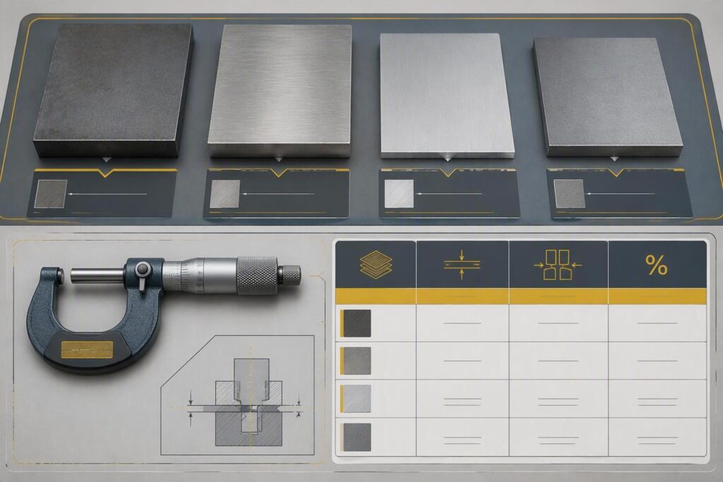
The band widens as the material gets stronger. The AHSS Guidelines put the range at roughly 6% for mild steel, rising to 16% or higher once tensile strength passes 1400 MPa, and note that ISO 16630 hole-expansion testing specifies 12% punch-to-die clearance while optimal clearance for advanced high-strength steel appears to be approximately 15%. Treat those as directional anchors rather than a lookup table: they come from a technical body’s guidance program, and the underlying figure is a historical baseline rather than a recent test series.
For AHSS and UHSS applications where standard D2 blades are reaching their clearance and wear limits, see the tungsten carbide inlaid shear blades ROI guide for AHSS lines for a full TCO comparison.
When to deviate
Deviate upward when the material work-hardens or when edge quality matters more than tool life. Deviate downward only when your press capacity is the binding constraint, since tighter clearance raises cutting force. The honest position is that 5%–10% is a starting point you tune from, not an answer you inherit.
Parallelism and thickness effects
Clearance is only as good as its consistency along the blade. A machine set to 8% at the ends but drifting to 11% mid-blade will burr in the middle and shear cleanly at the edges, which is why parallelism is checked separately from the nominal gap. Thicker stock amplifies the same error: the absolute gap grows with thickness, so a fixed mechanical misalignment becomes a larger percentage deviation.
Quy trình thiết lập chuẩn (SOP)
A repeatable shear blade clearance setup follows one sequence: baseline the gap, verify parallelism, lock, test cut, iterate. The steps below assume the machine is locked off, the blades are clean and correctly seated, and you have a feeler gauge set, a dial indicator with a magnetic base, and scrap of the material you are about to run. Budget 30 to 45 minutes for a first setup on a machine you do not know well.
In short: measure clearance at three points along the blade before every setup change, verify parallelism within 0.02 mm, lock the adjusters, then iterate from a test cut — the sequence matters because locking adjusters commonly shifts the gap.
Feeler gauge baseline
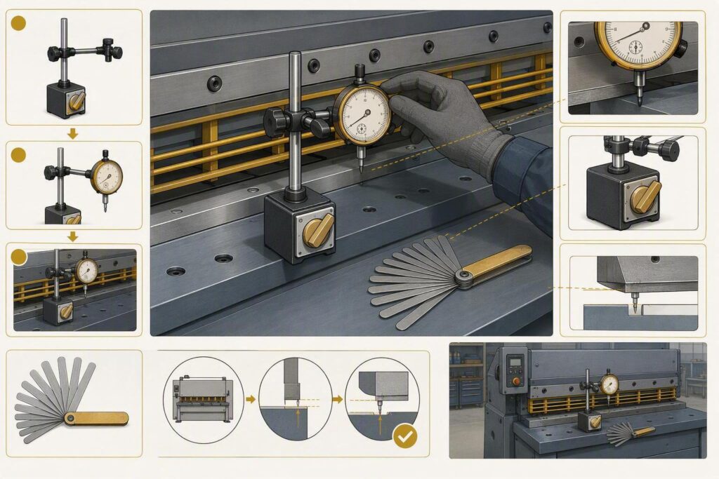
Set the upper blade to its lowest position and insert the feeler gauge stack at the left end, center, and right end of the blade. Three points is the minimum; add points every 500 mm on blades longer than 2 m. Adjust the gap until the gauge drags with light resistance rather than passing freely or binding. Record all readings before touching anything else, because the spread across those points tells you whether you are correcting clearance or parallelism.
Dial indicator calibration
Mount the dial indicator on the lower blade and sweep the upper blade through its stroke, recording readings at several positions along the length. Blades should sit within 02 mm of each other, and the gap needs immediate recalibration once it exceeds that. Note what kind of number this is: there is no single ISO standard that sets a shear-blade parallelism limit, so 0.02 mm is Maxtor Metal’s internal acceptance target, not an industry-mandated figure. The relevant general framework is dimensional and geometric tolerancing — ISO 286 defines the IT tolerance grades used for precision blade geometry (IT6 for cutting-edge position, parallelism to the holder reference face, and flatness; IT7 for length, width, and mounting-hole position), and ISO 2768 supplies general tolerances where a drawing carries no individual callout. Treat the 0.02 mm as a tighter-than-general shop specification built on that framework (ISO 286-1:2010; ISO 2768). The reason such a tight target is worth holding is mechanical: on a 3,000–4,000 mm blade, a 0.1–0.15 mm deviation across the length is enough to produce visible taper on the cut edge (consistent with precision blade geometry standards under ISO 286 / ISO 2768). Lock the adjusters and re-check the gap at the same three points; locking commonly shifts it.
Test cut and iteration
Run a slow test cut on scrap and read the edge. Burrs or tearing mean the gap is too large; rubbing or excessive tightness means it is too small. Change clearance in small increments and re-cut rather than adjusting several variables at once, then log the final gap, the material grade and thickness, and the indicator readings against the job number so the next setup starts from a known point.
Each regrind removes material from the blade thickness. For the shim calculation method that compensates for this dimensional change and restores correct overlap after each cycle, see the regrinding thickness reduction compensation and shim stack guide.
Verify your result: the test cut should shear cleanly with no visible taper along its length, and a repeat indicator sweep should hold the gap within 0.02 mm after the adjusters are locked.
Trường hợp thực tế: khắc phục hiện tượng bavia quá mức trên thép S355 dày 6 mm
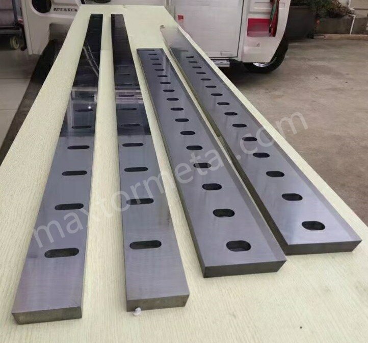
The clearest way to see why 5–10% is a starting rule and not a fixed answer is to walk through a commissioning-style troubleshooting case. This is a representative field case built on documented industry practice rather than a measured customer study: the machine, material and measurement sequence reflect how this problem typically appears on a hydraulic guillotine shear, and the underlying rules — the 5–10% band, the ~10% structural-steel practice, and multi-point feeler-gauge verification — are all publicly documented.
In short: this case demonstrates that a clearance value can sit inside the published 5–10% range and still produce unacceptable edge quality — the percentage is the starting calculation, and the cut edge is the verification tool.
The situation
| Tham số | Giá trị |
|---|---|
| Ứng dụng | Hydraulic guillotine shear |
| Vật liệu | S355 structural steel |
| Nominal thickness | 6.0 mm |
| Measured thickness | 5.94–6.06 mm across the test sheets |
| Lưỡi kiếm | Hardened cold-work tool-steel shear blades |
| Initial clearance | ~0.30 mm |
| Target window | ~0.30–0.60 mm (5–10% starting rule) |
The problem appeared after the machine was switched from thinner sheet to 6 mm structural steel. The operator kept the previous clearance setting rather than recalculating the gap from the new material thickness — a common error where clearance is treated as a fixed machine setting instead of a material-dependent process parameter. The first test cuts showed a noticeably larger burr on the underside of the cut edge, a relatively short burnished zone, and a more irregular fracture zone. The operator suspected dull blades and considered replacing them.
Attempt 1 — replace the blades (rejected)
The first response was to suspect blade wear. Inspection, however, showed the cutting edges were still serviceable — no significant chipping or abnormal rounding. Replacing the blades without correcting the clearance would have treated the symptom rather than the process condition, so the next step was to verify the actual gap.
Measurement sequence
The machine was stopped and isolated per the site’s maintenance procedure. Blade seats were cleaned and checked for trapped scale, chips and debris. Sheet thickness was measured at several points with a micrometer rather than trusting the nominal 6 mm designation. Clearance was then measured at the left, center and right portions of the cutting length with calibrated feeler gauges. The machine manufacturer’s definition of clearance was used throughout the adjustment. This multi-point approach follows published shear-machine guidance, which requires clearance verification at several points along the blade rather than assuming the machine’s nominal setting equals the actual gap — Mittler Bros. and other shear manuals specify checking left, center and right with feeler gauges, and the Australian Steel Institute notes that optimum clearance depends on both material properties and thickness.
Attempt 2 — keep the 5% setting (insufficient)
After measurement, the initial gap was approximately 0.30 mm — about 5% of the measured 6 mm thickness:
6.0 mm × 5% = 0.30 mm
That value was technically inside the general 5–10% starting range, yet edge quality remained unsatisfactory. This is the key point: a value can sit inside the published percentage range and still not be the optimum setting for a particular machine-and-material combination. Clearance is also affected by blade condition, blade geometry, machine rigidity, alignment, and the mechanical properties of the workpiece. Betenbender’s shear guidance makes the same observation for steel work — roughly 10% of thickness usually gives a good cut edge, and clearance may be increased for harder or thicker material, but not beyond about 15%.
Attempt 3 — increase clearance (resolved)
Clearance was increased progressively toward approximately 0.50–0.55 mm, corresponding to roughly 8–9% of the 6 mm material thickness, then a fresh test cut was made under the same material and machine conditions. Edge quality improved visibly. The important caveat: this is not a claim that 0.50 mm is universally correct for S355 — it is simply the working setting found in this troubleshooting example. Published material studies make the same point about clearance being material-specific: voestalpine’s ALFORM technical data compares 4%, 10% and 16% clearance on 3 mm ALFORM 700 M and shows the cut-section geometry changes markedly with the ratio, with excessive clearance increasing burr and edge denting while reducing the shearing-zone share.
Effect, recorded honestly
Rather than inventing precise burr-height numbers, a credible record notes the observable change:
| Tham số | Initial condition | After adjustment |
|---|---|---|
| Vật liệu | S355 | S355 |
| Nominal thickness | 6 mm | 6 mm |
| Measured thickness | 5.94–6.06 mm | 5.94–6.06 mm |
| Khe hở | ~0.30 mm | ~0.50–0.55 mm |
| Clearance ratio | ~5% | ~8–9% |
| Blade condition | Serviceable | Same |
| Test batch | Same heat / comparable material | Same |
| Burr | Pronounced / unacceptable | Visibly reduced |
| Cut edge | Irregular fracture zone | More uniform fracture |
| Blade change | Not required | Not required |
If a team wants to make this rigorous, the fields worth adding are burr height (mm), rollover height (mm), burnished-zone and fracture-zone percentages, cut-angle deviation, machine hydraulic pressure, number of strokes, and blade edge radius.
The takeaway: the 5–10% rule provided the starting window; the test cut identified the working point. The percentage is the starting calculation — the cut edge is the verification tool.
This chain is worth internalising: 5–10% rule → 6 mm S355 gives a 0.30–0.60 mm starting window → measurement shows 0.30 mm gives poor edge quality → step up to ~0.50–0.55 mm → test cut confirms the improvement → do not market 0.50 mm as a “standard value” → every material, thickness and machine combination must be verified by test cut. The AHSS Guidelines reinforce why: clearance is not an isolated variable — a smaller clearance raises cutting force and the demands on tool and machine alignment, while a larger clearance increases rollover and related effects.
Kiểm soát chất lượng (QC) và bảo trì

In short: set a numeric burr height limit before the job starts, log clearance and material lot per job, and treat rising burr height or an edge radius above 0.2 mm as mandatory regrind triggers — not subjective judgements.
Burr height limits and triggers
Burr height is the fastest field check on a shear, and it is the one most often left unmeasured. Set a numeric limit before the job starts, then treat any exceedance as a trigger rather than a nuisance.
A practical default is 5% of material thickness. On 3 mm mild steel that is 0.15 mm, measurable with a deburring gauge or a bench micrometer across the burr crest. Project drawings and customer acceptance criteria override the default whenever they are tighter.
Two triggers should stop the line:
- Burr height above tolerance on two consecutive cuts after a clearance check.
- Edge radius at or above 0.2 mm, measured on the blade bevel with a radius gauge or a 20× magnifier.
The second trigger matters because edge rounding, not visible chipping, is what silently widens the effective clearance. A blade that looks serviceable can already be cutting 0.05 mm wider per side than the setup sheet says. As with the parallelism target, the 0.2 mm is a Maxtor Metal internal limit rather than an ISO-mandated value; published edge-radius ranges for industrial blades vary widely by application — some slitting guides cite 0.05–0.30 mm, disc-shear references hold below 0.05 mm, and general deburring practice references edge-break specifications such as ISO 13715. That spread is exactly why you set the limit against your own acceptance criteria rather than assuming one number fits every line.
For a measurement-based rotation trigger and audit-ready log template that standardises this decision across an entire blade inventory, see the 4-edge reversible blade rotation schedule and regrind criteria SOP.
Mẹo chuyên nghiệp: Log clearance, material lot, and burr height per job in one sheet. After a few weeks the log shows whether drift tracks a specific material lot, a specific operator, or the blade itself, which turns regrind scheduling from guesswork into a trend line.
Defect diagnosis and corrective actions
Match the defect to the cause before touching the blade. Most burr and edge complaints trace back to one of four conditions, and each has a different fix.
| Khuyết điểm | Nguyên nhân có thể xảy ra | Biện pháp khắc phục |
|---|---|---|
| Tall, rolled burr on one side | Clearance too wide on that side | Re-check parallelism, reduce gap toward the lower band |
| Short, brittle burr with edge chipping | Clearance too tight | Open the gap, inspect the bevel under 20× magnification |
| Burr varies along the cut length | Blade not parallel or ram misalignment | Re-shim and verify straightness before the next setup |
| Clean cut, sudden burr spike mid-run | Edge wear or chipping | Measure edge radius, then decide regrind or replace |
When chipping appears suddenly or in a consistent location along the blade, the defect pattern itself carries diagnostic information. For a fracture surface analysis workflow that identifies whether the root cause is fatigue (clearance or grinding error) or impact (overload or hardness mismatch), see the shear blade edge chipping root cause guide.
That last decision follows a chipping-depth ladder. Light chipping under 0.2 mm clears with standard stock removal of 0.25–0.35 mm. Moderate chipping between 0.2 mm and 0.5 mm needs deeper removal and a 20× inspection of the bevel. Severe chipping above 0.5 mm means scrap or a major removal that can push the blade past its dimensional safety limit. The floor on any regrind is 0.254–0.381 mm of stock removal, because micro-fractures from running a blade past its sharpening window penetrate 0.25–0.40 mm below the bevel and will surface again if that layer is left in place (Maxtor Metal regrind-or-replace criteria for shear blades, retrieved 2026-08-27).
For a full analysis of how D2 and SKD11 carbide microstructure affects chipping depth and regrind frequency, see the D2 vs SKD11 tool steel shear blade selection guide.
Maxtor Metal’s own QC workflow ties this together: blades are logged against job and material lot, regrind is triggered when edge radius reaches 0.2 mm or burr height exceeds project tolerance, and every returned blade is re-verified for straightness under 0.02 mm/m, parallelism under 0.015 mm, and hardness across the full length before it goes back into rotation. These too are internal acceptance limits, set tighter than the general ISO 2768 / ISO 286 framework rather than drawn from a single published shear-blade standard. The point of the record is not the paperwork. It is knowing which of your four-edge reversible blades still has usable edges and which one is one bad cut away from a scrap decision.
FAQs:
Hỏi: Quy tắc 5–10 phần trăm đối với khe hở lưỡi dao cắt tấm là gì?
Đáp: Quy tắc này thiết lập khe hở lưỡi dao cắt tấm ở mức từ 5% đến 10% độ dày vật liệu. Đối với thép mềm dày 10 mm, mức này tương đương 0,5–1,0 mm. Khoảng giá trị này sẽ thu hẹp lại khi giới hạn bền kéo tăng lên: nhôm mềm nằm ở phía trên, trong khi thép không gỉ và thép hợp kim cường độ cao (HSLA) nằm ở phía dưới. Hãy coi đây là điểm khởi đầu và xác nhận lại bằng một đường cắt thử trên mẻ vật liệu thực tế.
Hỏi: Khe hở lưỡi dao cắt tấm tính theo từng bên hay tính tổng?
Đáp: Cả hai quy ước này đều xuất hiện trong các bảng thông số đã công bố, và việc nhầm lẫn giữa chúng sẽ làm gấp đôi khe hở của bạn. Maxtor Metal quy định mức khuyến nghị 5–10% là khe hở lưỡi dao tính trên mỗi bên, do đó đối với thép mềm dày 10 mm, khe hở sẽ là 0,5–1,0 mm cho mỗi bên, hoặc tổng cộng 1–2 mm. Hãy kiểm tra xem nhà chế tạo máy của bạn sử dụng quy ước nào trước khi tiến hành cài đặt bất cứ thông số gì.
Hỏi: Tôi nên đặt khe hở bao nhiêu cho thép mềm dày 6 mm?
Đáp: Hãy bắt đầu ở mức 0,3–0,6 mm và kiểm tra lại qua mép cắt. Mép cắt sạch, vuông vức với một dải bóng nhẹ có nghĩa là bạn đã ở rất gần thông số chuẩn; hiện tượng bo tròn mép quá mức hoặc bavia lởm chởm có nghĩa là khe hở quá rộng. Hãy đo chiều cao bavia thay vì chỉ đánh giá bằng mắt常.
Hỏi: Tôi có thể sử dụng cùng một mức khe hở cho thép không gỉ và thép mềm hay không?
Đáp: Không. Thép không gỉ, thép HSLA và các mác thép có độ bền cao hơn đòi hỏi khe hở khít hơn, thường nằm ở mức cận dưới của phạm vi, vì chúng chống lại biến dạng dẻo và bị gãy sớm hơn. Việc áp dụng khe hở của thép mềm cho thép không gỉ sẽ gây ra hiện tượng nứt mép cắt và làm mòn lưỡi dao nhanh hơn.
Hỏi: Tôi nên mài lại lưỡi dao cắt tấm bao lâu một lần?
Đáp: Chiều cao bavia là tiêu chí thực tế để kích hoạt việc mài lại: thông lệ thông thường là giữ chiều cao bavia dưới 10% độ dày kim loại, và sự gia tăng chiều cao bavia cho biết cả độ mòn của dụng cụ lẫn độ tăng khe hở (theo Hướng dẫn AHSS). Đối với thép cường độ cao tiên tiến (AHSS), chỉ số chiều cao bavia đơn thuần là một tín hiệu yếu, do đó chất lượng mép cắt mới là chỉ báo tốt hơn. Quy trình vận hành riêng của Maxtor Metal sử dụng bán kính mép cắt 0,2 mm hoặc khi chiều cao bavia vượt quá dung sai của dự án, tùy theo điều kiện nào đến trước.
Hỏi: Làm thế nào để kiểm tra độ song song của lưỡi dao cắt tấm?
Đáp: Sử dụng một đồng hồ so (dial indicator) gắn trên đế từ, trượt dọc theo toàn bộ chiều dài lưỡi dao trong khi máy đã được khóa và ngắt nguồn. Maxtor Metal kiểm chứng độ thẳng dưới 0,02 mm/m và độ song song dưới 0,015 mm tại xưởng — đây là các giới hạn nghiệm thu nội bộ được xây dựng dựa trên khung dung sai chung ISO 2768 / ISO 286, do đó chúng là tiêu chuẩn tham chiếu hợp lý cho một cỗ máy đang vận hành chứ không phải là con số bắt buộc của mọi tiêu chuẩn chung. Hãy kiểm tra lại sau mỗi lần mài lại hoặc thay thế lưỡi dao.
Hỏi: Tại sao máy cắt của tôi lại để lại vết cắt kép (double cut)?
Đáp: Vết cắt kép thường có nghĩa là khe hở quá lớn so với độ dày vật liệu, khiến vật liệu bị uốn cong vào khe hở và bị gãy hai lần thay vì một lần. Hiện tượng này cũng có thể xuất phát từ lực kẹp giữ phôi (hold-down force) không đủ hoặc do lưỡi dao đã bị cùn. Hãy điều chỉnh thu hẹp khe hở về phía cận dưới của phạm vi và kiểm tra áp lực kẹp phôi trước khi đổ lỗi cho lưỡi dao.
Kết luận
Khe hở lưỡi dao cắt tấm là một quyết định điều chỉnh thông số, không phải là một con số cố định, và quy tắc 5–10% cung cấp cho bạn một điểm khởi đầu có cơ sở thay vì một câu trả lời mang tính rập khuôn. Khoảng giá trị này kiểm soát đồng thời hai yếu tố: tỷ lệ vùng bóng (burnish) và vùng gãy trên mép cắt, cũng như mức độ bo tròn mép (rollover) và bavia để lại sau khi cắt. Cài đặt chuẩn xác và mặt cắt sẽ giữ được độ sạch; nếu đi chệch khỏi khoảng này, bạn sẽ đổi lỗi này lấy lỗi khác.
Điều phân biệt giữa một quy trình được kiểm soát và một quy trình ăn may chính là tiêu chuẩn hóa. Hãy ghi lại khe hở bạn đã cài đặt cho mỗi đơn hàng, ghi nhận mác thép và độ dày vật liệu tương ứng, đồng thời kiểm tra tình trạng mép cắt theo định kỳ thay vì chờ đến khi có khiếu nại về bavia. Theo dõi các chu kỳ mài lại dựa trên các nhật ký ghi chép đó để bạn có thể nhìn thấy độ mòn của mép cắt trước khi nó xảy ra lỗi. Hãy coi đây là vấn đề về quy trình làm việc cũng như vấn đề về lưỡi dao: cùng một giá trị khe hở sẽ có biểu hiện khác nhau giữa các ca làm việc nếu không ai ghi chép lại.
Nếu bạn đang thiết lập một máy cắt mới hoặc tiêu chuẩn hóa một máy đang có sẵn, hãy đối chiếu thông số kỹ thuật của lưỡi dao với hỗn hợp vật liệu và chu kỳ làm việc của bạn trước khi đưa ra một con số cố định. Khi vật liệu hoặc ứng dụng nằm ngoài các khoảng thông thường, hãy trao đổi với kỹ sư ứng dụng về những điểm mà quy trình của bạn cần thay đổi và lý do tại sao.
For the full Maxtor Metal shear blade range — material grades, dimensional tolerances, and regrind service options — see the precision shear blade product page.
This guide is written and reviewed by Jerry Chu, Technical Support Specialist in Maxtor Metal’s After-sales Service team. Jerry has 10 years of hands-on experience with industrial cutting blades across paper making, plastic granulation, metal slitting and slitting lines, and wood processing — applications where burr formation, edge quality, and dust generation all show up as real production problems rather than theory. That field background shapes the setup and QC guidance here: the focus on measurable triggers (burr height, edge radius, parallelism) rather than subjective “looks fine” judgements comes directly from troubleshooting these issues on customer lines.
Jerry holds PMP (Project Management Professional) and CMRP2 certifications, which support the process-discipline approach — logging, standardised setup, and scheduled inspection — that runs through this article.
Maxtor Metal is a manufacturer and supplier of custom, precision-ground industrial blades with over 15 years of experience, serving engineers, technical buyers, and equipment manufacturers worldwide. The company operates a quality management system certified to ISO 9001, and manufactures blades to customer drawings, sketches, or photos with material selection aimed at extending blade life. The internal tolerance and regrind figures quoted in this article come from that QC workflow.

 English
 Spanish
 Italian
 French
 Portuguese
 Russian
 German
 Arabic
 Hindi
 Vietnamese
 Indonesian
 Japanese
 Korean