

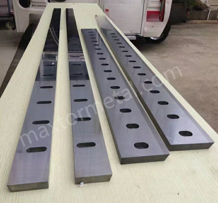
Trả lời nhanh: Dao cắt gắn hợp kim Tungsten Carbide thường mang lại tuổi thọ lưỡi cắt cao gấp 2–3,5 lần so với dao thép D2 trên các dây chuyền AHSS. ROI đạt được chủ yếu nhờ giảm tần suất thay dao và giảm phế phẩm do chất lượng cạnh cắt không ổn định, chứ không chỉ dựa vào giá thành bản thân lưỡi dao. Kiểm soát khe hở và khôi phục chính xác hình học dao khi mài lại là hai biến số quyết định việc duy trì bội số tuổi thọ này trong sản xuất thực tế.
Các dây chuyền AHSS/UHSS công suất cực cao thường không thất bại vì dao «không cắt được». Chúng thất bại do những biến động nhỏ — mẻ lưỡi cắt, lệch độ cao ba-via, thay đổi khe hở khi mang tải hoặc hình học mài lại không đồng đều — âm thầm biến thành thời gian dừng máy, phế phẩm và sụt giảm hiệu suất OEE.
Cẩm nang này dành cho các quản lý sản xuất & bảo trì, kỹ sư công nghệ và chuyên viên thu mua kỹ thuật đang vận hành (hoặc nâng cấp) dây chuyền cắt tấm theo chiều dài (CTL) và máy cắt chém phù hợp với thép AHSS. Nếu bạn đang đánh giá dao cắt gắn hợp kim carbide, mục tiêu không phải là chạy theo con số «tăng tuổi thọ» trên lý thuyết — mà là xây dựng một bài toán ROI có tính thực tế cao, vững chắc ngay cả khi đã tính đến cơ cấu mác thép, thời gian thay dao và chu kỳ mài lại.
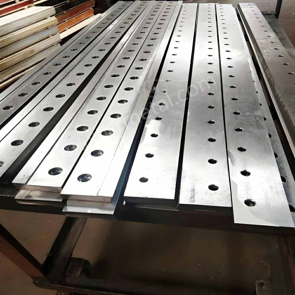
Để tham khảo các cấu hình lưỡi dao cắt tấm tiêu biểu và định dạng đặt hàng, bạn có thể bắt đầu với lưỡi dao cắt tấm Maxtor Metal trang này—sau đó sử dụng mô hình và các điểm kiểm tra bên dưới để xác định mức độ phù hợp và tính kinh tế cho dây chuyền cụ thể của bạn.
- Hướng dẫn này dành cho ai và bối cảnh về AHSS/UHSS
- Những thay đổi về năng suất cực cao ảnh hưởng thế nào đến việc lựa chọn và bảo trì lưỡi dao
- Lưỡi dao cắt tấm cấy hợp kim Tungsten Carbide ảnh hưởng thế nào đến tuổi thọ, kiểm soát ba-via và TCO
Khi cắt thép AHSS, phạm vi thông số cắt (cutting window) bị thu hẹp do độ bền vật liệu cao, nhiệt độ và hiện tượng bám dính (adhesion) diễn ra khắc nghiệt hơn, đồng thời sai số tích lũy (độ võng máy + lực kẹp + độ song song) ảnh hưởng lớn hơn. Hướng dẫn về AHSS của WorldAutoSteel chỉ ra rằng khe hở cắt (clearance) thường tăng theo độ bền — từ khoảng 6% độ dày phôi đối với thép cacbon thấp tăng lên khoảng 16% hoặc cao hơn khi độ bền kéo vượt quá ~1400 MPa — đồng thời nhấn mạnh độ cao ba-via có thể ít tin cậy hơn khi dùng làm chỉ số đánh giá độ mòn dao đối với AHSS so với thép thường (vì vậy việc giám sát chất lượng cạnh cắt trở nên quan trọng hơn).
Ở công suất cực cao, điều thay đổi rất đơn giản: bạn không chỉ cần những lưỡi dao «cứng hơn». Bạn cần một hệ thống giữ cho cạnh cắt ổn định giữa các kỳ bảo trì kế hoạch — chu kỳ mài lại có thể dự đoán, công đoạn chuẩn bị cạnh cắt (edge prep) được kiểm soát, và quy trình QC ngăn ngừa sự sai lệch hình học giữa các lô hàng.
Lưỡi dao cắt tấm cấy hợp kim Tungsten Carbide thường được đánh giá dựa trên ba lý do thực tế:
- Độ ổn định của tuổi thọ chống mài mòn tại cạnh cắt (đặc biệt là khi mác thép và điều kiện bề mặt thay đổi)
- Kiểm soát ba-via theo thời gian (ít bị sai lệch hơn khi cạnh cắt bị cùn)
- Tổng chi phí sở hữu (TCO) thấp hơn khi bạn tính đến thời gian thay dao, số lần mài lại và phế phẩm
Lưu ý kỹ thuật: Lưỡi dao cắt tấm cấy hợp kim Tungsten Carbide là dụng cụ cắt chính xác, trong đó phần cạnh hợp kim Tungsten Carbide hàn đồng được tích hợp vào thân thép hợp kim D2 hoặc H13, kết hợp độ dẻo dai của thép công cụ với khả năng chống mài mòn của carbide tại mặt cắt. Đối với các dây chuyền cắt tấm AHSS và UHSS, cấu trúc này giúp kéo dài độ ổn định của cạnh cắt giữa các lần mài lại và giảm thiểu sự sai lệch ba-via trong điều kiện mác thép và bề mặt thay đổi—với điều kiện là việc kiểm soát khe hở, căn chỉnh và khôi phục biên dạng mài lại được duy trì tốt. [→ Xem tổng quan kỹ thuật về lưỡi dao cắt tấm Maxtor Metal]
Đánh giá hiệu suất dao cắt gắn hợp kim Tungsten Carbide
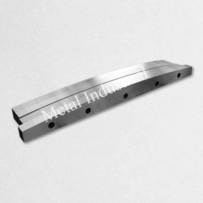
Hệ số nhân tuổi thọ so với thép D2/thép hàm lượng vanadium cao
Lưỡi dao cấy hợp kim carbide thường mang lại hiệu quả đầu tư (ROI) khi dạng hư hỏng hiện tại của bạn là hỏng cạnh cắt (mẻ nhỏ, mài mòn nhanh ở cạnh cắt, ba-via không ổn định) thay vì một sự cố va chạm cơ học đơn lẻ.
Thay vì dựa vào tuyên bố chung chung “tuổi thọ gấp X lần”, hãy đối chiếu với hai chỉ số có thể đo lường tại nhà máy:
- Số mét (hoặc tấn) trên mỗi cạnh cắt sắc cho đến khi đạt đến ngưỡng giới hạn chất lượng
- Độ ổn định của thời gian đạt ngưỡng trên các mác thép hỗn hợp (cùng một lưỡi dao không nên hoạt động như hai công cụ khác nhau khi bạn chuyển từ HSLA sang AHSS)
Một cách hữu ích để so sánh với thép công cụ D2 hoặc thép hàm lượng vanadium cao là chạy thử nghiệm có kiểm soát trên 2–3 mác thép hàng đầu của bạn và một điều kiện “tệ nhất” (vật liệu có lớp phủ, lớp vảy bề mặt dày hơn hoặc quy trình hạ nguồn nhạy cảm với ba-via nhất của bạn). Mô hình ROI ở phần sau của hướng dẫn này sẽ giúp bạn chuyển đổi bất kỳ tỷ lệ tuổi thọ quan sát được nào thành chi phí trên mỗi mét/tấn.
Độ sâu phần cấy, độ bóng cạnh cắt và các mục tiêu mài vát vi mô (micro-hone)
Đối với các dây chuyền AHSS, cạnh cắt thực hiện hai nhiệm vụ cùng lúc: nó phải chống mài mòn do cọ xát/bám dính trong khi vẫn đủ dẻo dai để tránh bị mẻ giòn.
Ba thông số sau đây thường quyết định kết quả:
- Độ sâu phần cấy: Phần cấy sâu hơn thường cho phép tổng số lần mài lại nhiều hơn trước khi đạt đến giới hạn của phần cấy.
- Độ bóng cạnh cắt: Độ bóng bề mặt tại mặt cắt ảnh hưởng đến ma sát, sự sinh nhiệt và độ bám dính.
- Mài vát vi mô (Micro-hone): Việc mài vát vi mô (micro-hone) có kiểm soát giúp giảm “độ giòn của lưỡi dao” và có thể cải thiện độ ổn định của cạnh cắt, đặc biệt là khi khe hở không đồng đều hoàn hảo trên toàn bộ chiều dài.
Các giá trị mục tiêu tốt nhất phụ thuộc vào độ dày, độ bền và việc dây chuyền của bạn bị giới hạn bởi ba-via hay giới hạn bởi hình học. Chìa khóa là xác định các tiêu chí nghiệm thu (xem phần QC) để các lần mài lại không âm thầm làm sai lệch góc mài vát vi mô (micro-hone) và thay đổi đặc tính ba-via của bạn.
Để tham khảo chung, chiều rộng phần cấy trong khoảng 3–6 mm là phổ biến đối với lưỡi dao cắt guillotine và lưỡi dao cắt tấm CTL; độ sâu phần cấy được quyết định bởi lượng dư độ dày lưỡi dao và tổng số chu kỳ mài lại được yêu cầu.
Tại Maxtor Metal, các lưỡi dao cắt tấm cấy hợp kim carbide được sản xuất với hình học phần cấy được ghi chép đầy đủ và hồ sơ độ bóng bề mặt sau khi mài, đảm bảo các thông số kỹ thuật về mài vát vi mô (micro-hone) và mặt cắt được thiết lập tại nhà máy có thể truy xuất được trong suốt chu kỳ mài lại.
Ngưỡng kích hoạt chu kỳ mài lại và số lần mài thông thường
Trên thép mềm, chiều cao ba-via thường tăng lên theo độ mòn và có thể là một yếu tố kích hoạt trực tiếp. Trên AHSS, Hướng dẫn AHSS của WorldAutoSteel lưu ý rằng chiều cao ba-via có thể duy trì tương đối ổn định ngay cả khi dụng cụ bị mòn, đó là lý do tại sao một bộ chỉ số kích hoạt rộng hơn sẽ an toàn hơn.
Sử dụng hai yếu tố kích hoạt: một cho chất lượng cạnh cắt và một cho rủi ro.
- Các yếu tố kích hoạt chất lượng cạnh cắt (chọn yếu tố ảnh hưởng nghiêm trọng nhất đến quy trình hạ nguồn của bạn):
- sự sai lệch độ nhám vùng đứt gãy
- vùng chuyển tiếp miết bóng/đứt gãy không đều
- vết mẻ nhỏ hoặc vết xước đường có thể nhìn thấy bằng mắt thường liên quan đến sự sai lệch ba-via
- Các yếu tố kích hoạt rủi ro:
- rising changeover time due to alignment fight
- increasing adjustment frequency to hold tolerance
- increased scrap events clustered after grade switches
These trigger sets map directly to common search queries like shear blade regrind interval and help you standardize when operators should intervene.
Typical total regrind counts vary with inlay depth, blade thickness allowance, and how tightly geometry is restored each cycle. The practical point: you should be able to predict an expected cycle count band before you commit, because the ROI model depends on it.
Thiết lập và kiểm soát sự cố
Setup is where most ROI is won or lost. A premium blade running in a drifting setup becomes an expensive consumable.
If your top complaint is burr control in AHSS shearing drifting over a run, the two levers that usually matter most are (1) holding clearance uniformity end-to-end and (2) keeping edge prep consistent after each regrind. Sample edge-zone appearance on a fixed cadence (by coil count or shift) and correlate it with adjustment frequency and regrind events.
Clearance targets for thin AHSS and stainless
For thin AHSS and stainless, think in clearance as a percent of thickness, then verify it stays consistent end-to-end under real clamping.
WorldAutoSteel’s AHSS Guidelines discuss that clearance commonly increases with strength (from ~6% to ~16%+ in higher-strength regimes), and also caution that both too-small and too-large clearances create distinct failure modes.
Practical targets to start from (then validate with test cuts and edge inspection):
- AHSS shearing blade clearance: start in the 10–16% of thickness range for higher strengths, and adjust based on edge appearance and cracking sensitivity.
- Stainless (thin gauges): often needs higher clearance than mild steel to avoid double-shear and excessive work hardening; validate with edge zone appearance and burr behavior.
Điểm chính: In AHSS, don’t treat burr height alone as your “clearance is right” signal—monitor the full cut-edge zone behavior and stability over time.
Alignment, rake angle, and uniform clamping
If you only implement one discipline change for AHSS, make it this: treat parallelism and clamping uniformity as quality variables, not maintenance variables.
- Alignment: verify parallelism at multiple points along the blade length, not just at the ends.
- Rake angle: choose a rake strategy consistent with your material mix; extreme angles can reduce force but can also change deformation patterns on thin materials.
- Clamping: non-uniform clamping creates local clearance spikes; those spikes tend to be where chipping starts and where burr drift becomes “mysterious.”
Heat, adhesion, and edge-prep strategies
AHSS and stainless amplify two problems: heat Và sự bám dính.
- Heat: higher load plus friction can soften local zones and accelerate wear; heat also amplifies micro-chipping risk when the edge is too sharp.
- Adhesion: stainless in particular can “pick up” and smear; that changes effective clearance and can cause edge marking.
Edge-prep strategies that tend to stabilize behavior:
- use a controlled micro-hone rather than a fragile razor edge
- keep cutting faces consistent in finish after each regrind
- if adhesion is the dominant issue, focus on surface condition and cleaning discipline (adhesion layers become a geometry change)
Quy trình mài lại và kiểm soát chất lượng (QC)
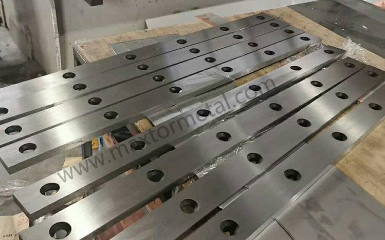
Inlay limits, regrind steps, and total allowable cycles
Carbide inlay changes the regrind question from “how many times can we sharpen?” to “how many times can we sharpen before we compromise the inlay system?”
Your protocol should define:
- minimum remaining inlay depth (stop point)
- maximum allowable thickness loss per regrind
- how you preserve the edge prep (micro-hone) across cycles
- a rule for when a blade is “regrindable” vs “scrap” (cracks, braze integrity concerns, geometry loss)
For the shim calculation method used to compensate for thickness loss after each regrind cycle, see the regrinding thickness reduction compensation and shim stack guide.
Geometry restoration, surface finish (Ra), and acceptance criteria
Regrind ROI only works if geometry restoration is disciplined.
Recommended acceptance criteria categories:
- Hình học
- straightness along the cutting edge
- parallelism across the length
- consistent bevel geometry (no “soft corner” drift)
- Độ bóng bề mặt
- cutting face finish should be controlled and repeatable (track Ra or an equivalent surface-finish measure)
- Edge condition
- no micro-chipping beyond your defined threshold
- consistent micro-hone (do not allow “sharper every time” drift)
Maxtor Metal’s post-grind acceptance protocol covers all three categories above—geometry, surface finish, and edge condition—with traceable inspection records returned with each regrind batch.
For documentation of edge requirements on drawings, the standard for indicating undefined edge requirements in technical product documentation is ISO 13715:2017. Even if you don’t use the symbology directly, aligning your internal acceptance language to a recognized standard reduces ambiguity between shifts, suppliers, and regrind vendors.
Maxtor Metal supports carbide-inlaid blade manufacturing with in-process QC checks and can provide regrind service with traceable inspection records, which helps keep geometry and batch consistency under control.
Documentation, MTCs, and batch consistency checks
For AHSS lines, procurement risk is often hidden in variation: the như nhau part number behaves differently across batches.
A practical documentation pack for each batch should include:
- MTC / material traceability for the base body and inlay material where applicable
- hardness / heat-treatment evidence where relevant
- inspection reports for key dimensions (thickness, straightness, parallelism)
- regrind history log (cycle count, removed stock, post-grind inspection)
This doesn’t have to be bureaucratic. The point is to make root-cause work fast when you see burr drift or chipping: you can separate setup issues from batch variation.
Mô hình tổng chi phí sở hữu (TCO) và ROI
Inputs, formulas, and amortization logic
The TCO structure below reflects how Maxtor Metal frames cost conversations with high-throughput AHSS lines: total cost per meter, not blade price.
A useful ROI model turns “blade life” into cost per meter (or cost per ton) and adds the costs that typically dominate in high-throughput lines: downtime and scrap.
This is the backbone for a practical total cost of ownership for shear blades comparison, because it forces every assumption (life, regrinds, changeover minutes) into the same unit.
Define these inputs:
C_blade: purchase cost of one blade setN_edges: usable edges per set (including flips/rotations if applicable)L_edge: meters (or tons) per edge between regrinds/replacementsN_regrinds: total regrinds achievable before scrap (bounded by inlay limit + geometry tolerance)C_regrind: cost per regrind cycleT_change: changeover time per event (hours)C_downtime: fully-loaded downtime cost per hourC_scrap: scrap/rework cost per ton (or per meter)S_scrap: scrap rate attributable to cut-edge instability (as a fraction)
A simple amortization structure:
- Blade amortization per meter
Copy-and-paste ROI calculator template
If you want a template that’s easy to move into Excel, start with this table and fill in your own line data. Keep units consistent (meters hoặc tons) across every row.
| Input | Symbol | Your value | Units / notes |
|---|---|---|---|
| Blade set purchase cost | C_blade | $ per set | |
| Usable edges per set | N_edges | count (include flips/rotations) | |
| Life per edge to trigger | L_edge | meters/edge or tons/edge | |
| Total regrinds before scrap | N_regrinds | count (bounded by inlay + tolerances) | |
| Regrind cost per cycle | C_regrind | $ per regrind | |
| Changeover time per event | T_change | hours/event | |
| Downtime cost | C_downtime | $/hour (fully loaded) | |
| Scrap cost | C_scrap | $/ton or $/meter | |
| Scrap rate due to cut-edge instability | S_scrap | fraction (e.g., 0.009 = 0.9%) | |
| Đầu ra | Công thức | Kết quả | Ghi chú |
| — | — | — | — |
| Total life per blade set | Total_m | N_edges × L_edge × (N_regrinds + 1) | Use meters or tons consistently |
| Blade amortization per unit | Cost_blade_per_m | C_blade / Total_m | $/meter or $/ton |
| Regrind cost per unit | Cost_regrind_per_m | (C_regrind × N_regrinds) / Total_m | $/meter or $/ton |
| Downtime cost per unit | Cost_down_per_m | (T_change × C_downtime × (N_regrinds + 1)) / Total_m | Simplified; add extra events if unplanned |
| Scrap cost per unit | Cost_scrap_per_m | S_scrap × C_scrap | Convert units if needed |
| Total cost per unit | TCO_per_m | Sum of all costs above | Compare baseline vs carbide-inlaid |
This layout makes it easy to run the same model for baseline and carbide-inlaid scenarios, then compute deltas (TCO reduction, payback period, and ROI).
Cost_blade_per_m = C_blade / (N_edges × L_edge × (N_regrinds + 1))- Regrind cost per meter
Cost_regrind_per_m = (C_regrind × N_regrinds) / (N_edges × L_edge × (N_regrinds + 1))
- Downtime cost per meter (changeovers + regrinds)
Cost_down_per_m = (T_change × C_downtime × Events_total) / Total_meters
Then add scrap:
Cost_scrap_per_m = S_scrap × C_scrap(convert units consistently)
The ROI comparison is the delta:
ROI = (TCO_baseline - TCO_carbide) / Investment_delta
Example cost per meter/ton with placeholders
Below is a worked example using sample values to show how the math behaves. Replace the numbers with your own line data.
Assume:
C_blade = $6,000per setN_edges = 2L_edge = 200,000 mN_regrinds = 6C_regrind = $450
Total meters per set across life:
Total_m = N_edges × L_edge × (N_regrinds + 1) = 2 × 200,000 × 7 = 2,800,000 m- Blade amortization per meter:
$6,000 / 2,800,000 = $0.00214/m
- Regrind cost per meter:
($450 × 6) / 2,800,000 = $0.00096/m
If your dominant cost is downtime, you’ll see ROI swing heavily with changeover time.
Example downtime inputs:
T_change = 0.5 hoursper eventC_downtime = $3,000/hourEvents_total = 7(initial + 6 regrinds)
Downtime cost per meter:
($3,000 × 0.5 × 7) / 2,800,000 = $0.00375/m
This simple example shows why “unit blade price” often isn’t the lever—changeover hours and stability events are.
Sensitivity to gap control, grade mix, and regrind SLA
Three sensitivity levers usually dominate:
- Gap control (clearance uniformity)
- Poor gap control can erase life gains by triggering chipping and forcing early regrinds.
- Grade mix (strength + surface condition)
- If your schedule shifts toward higher-strength AHSS or more abrasive surface conditions, edge stability becomes more valuable.
- Regrind SLA (turnaround + consistency)
- Slow or inconsistent regrinds increase spare inventory requirements and increase the chance of geometry drift.
If you want one “finance-friendly” sensitivity output, model TCO under three scenarios (conservative / expected / optimistic) by varying only:
L_edge(life)T_change(changeover time)S_scrap(scrap attributable to edge instability)
A clean way to present sensitivity—without overfitting—is to vary only the assumptions that typically dominate TCO for high-throughput lines.
| Kịch bản | Life per edge L_edge | Changeover time T_change | Edge-instability scrap S_scrap | What it represents |
|---|---|---|---|---|
| Conservative | lower-bound of your pilot band | higher-bound of your observed changeover | higher-bound of edge-related scrap | Setup drift, rougher surface condition, slower regrind turnaround |
| Expected | median of pilot band | median changeover | median scrap attribution | Normal operating cadence and grade mix |
| Optimistic | upper-bound of pilot band | lower-bound changeover (best-practice SOP) | lower-bound scrap attribution | Tight clearance control + consistent regrinds + stable material |
When you present the result, show ranges (not a single point estimate) for TCO per meter/ton and downtime minutes avoided. This usually makes the business case more credible than a single ROI number.
Sổ tay hướng dẫn triển khai
SOPs for changeover, inspection, and regrind logistics
The three SOPs below apply across all pilot contexts and should be locked before you scale to full production.
For a complete measurement-based rotation and regrind decision SOP applicable to guillotine shear blades—including burr threshold bands, edge-use sequence, and audit-ready log templates—see the 4-edge reversible blade rotation schedule and regrind criteria SOP.
Kết quả thử nghiệm: Tóm tắt 3 trường hợp thực tế (đã ẩn danh)
The fastest way to defend an ROI decision is to capture a small, controlled pilot and report results in the same units your plant already tracks: coils between regrinds, burr stability, setup interventions, scrap/rework, and OEE minutes.
Below are three anonymized pilots that illustrate where carbide-inlaid blades tend to pay back first. Use them as structure, not as a promise—your results will depend on grade mix, clearance control, clamping repeatability, and regrind consistency.
Pilot Case 1 — AHSS CTL on DP980
Context
- Material: DP980 (980–1000 MPa)
- Thickness: 1.2–2.0 mm
- Line: Coil-to-Length (CTL)
- Coil condition: Pickled & Oiled, light mill scale+
- Blade: Carbide-inlaid blade: D2 body + brazed ultra-fine WC edge, supplied by Maxtor Metal
Baseline vs carbide-inlaid configuration
- Baseline blade: D2 tool steel, 60–61 HRC
- Carbide-inlaid blade: D2 body (59–60 HRC) + brazed ultra-fine WC edge
- Carbide width: 4 mm
- Edge hardness: ~89 HRA
Triggers and measurement
- Triggers after ~40–50 coils on baseline:
- burr height approaching 0.10 mm
- increasing blade clearance adjustment frequency
- more frequent first-piece rechecks
- Measurement sequence:
- per coil: burr height measured at left/center/right using a 50× toolmaker microscope
- every 10 coils: log max burr, clearance, and edge radius
Pilot results
| KPI | Baseline D2 | WC inlaid |
|---|---|---|
| Cuộc sống lưỡi kiếm | 1.0× | 2.9× |
| Coils between regrinds | 48 | 138 |
| Average burr | 0.082 mm | 0.039 mm |
| Unplanned setup events | 5/month | 2/month |
| Phế phẩm | 1.8% | 0.9% |
| OEE | 84.1% | 87.6% |
| Regrind SLA | — | 5 working days |
What this pilot taught
- DP980’s abrasiveness made edge-wear stability the primary lever.
- Keeping the same clearance settings used for D2 initially caused localized micro-chipping; a small clearance optimization restored stable behavior.
Pilot Case 2 — Guillotine line with heavy mill scale
Context
- Material: Hot rolled AHSS
- Thickness: 4–8 mm
- Line: Hydraulic guillotine
- Surface: heavy mill scale
- Blade: Carbide-inlaid blade: H13 body + brazed ultra-fine WC edge, supplied by Maxtor Metal
Baseline vs carbide-inlaid configuration
- Baseline blade: modified H13
- Carbide-inlaid blade: H13 body + brazed tungsten carbide edge; double-tempered
Triggers and measurement
- Scale-driven wear increased burr and forced frequent setup adjustments.
- Measurement:
- per shift: check burr, edge radius, and blade temperature
- weekly: verify straightness and flatness
Pilot results
| KPI | Trước | Sau đó |
|---|---|---|
| Cuộc sống lưỡi kiếm | 1.0× | 2.1× |
| Thay lưỡi dao hàng tháng | 4 | 2 |
| Setup time | 150 min/month | 70 min/month |
| Gia công lại | 2.4% | 1.3% |
| Edge chipping | occasional | significantly reduced |
| Regrind SLA | — | 7 calendar days |
What this pilot taught
- Mill scale remained the dominant wear source. Carbide improved wear resistance, but without scale removal the life multiplier was lower than in pickled/oiled conditions.
Pilot Case 3 — High-volume automotive CTL
Context
- Material: CP780 + DP780
- Thickness: 1.6–2.5 mm
- Line: high-speed CTL
- Annual output: >60,000 t
- Blade: Carbide-inlaid blade: D2 body + brazed ultra-fine WC edge, supplied by Maxtor Metal
Baseline vs carbide-inlaid configuration
- Baseline blade: premium D2
- Carbide specification: fine-grain WC, vacuum brazed
- Surface finish target after grinding: Ra ≤ 0.2 μm
Triggers and measurement
- High cadence required planned weekly stoppages; burr began to affect downstream weld quality.
- Measurement:
- first-piece: burr height
- every 20 coils: microscope check, clearance, edge radius
- every regrind: flatness, parallelism, thickness
Pilot results
| KPI | Trước | Sau đó |
|---|---|---|
| Cuộc sống lưỡi kiếm | 1.0× | 3.4× |
| Regrind interval | 2 tuần | 7 weeks |
| Max burr | 0.11 mm | 0.05 mm |
| Planned downtime | 9 h/month | 4 h/month |
| Customer edge claims | 3/quarter | 0–1/quarter |
| Estimated TCO | baseline | ~18% reduction(blade amortization + regrind + changeover inputs; calculated using TCO model above) |
| Regrind SLA | — | 3–4 working days |
What this pilot taught
- A fixed rotation + regrind schedule plus reinstall checks (parallelism + clearance) prevented installation variation from masking tooling differences. The ~18% TCO reduction was driven primarily by the regrind interval extension (2 weeks → 7 weeks) and the reduction in planned downtime (9 h/month → 4 h/month), with blade amortization contributing a smaller share at this throughput level.
A simple pilot record you can copy
Capture the pilot in one sheet so finance and production speak the same language:
- grade(s) + thickness range + surface condition
- meters/tons/coils to trigger (edge-quality + risk trigger)
- changeover minutes per event (median and worst 10%)
- scrap/rework attributable to cut-edge instability
- regrind SLA (days) and post-regrind acceptance results
- notes on clearance settings, clamping repeatability, and any setup changes during the pilot
Treat the blade as part of a controlled process, not a consumable:
- Changeover SOP: torque pattern, clamp inspection, parallelism verification points
- Inspection SOP: define the edge-quality triggers that force action (not just “looks dull”)
- Regrind logistics SOP: tagging, cycle counting, and post-regrind acceptance checks
Data capture, dashboards, and KPIs for OEE and quality
If you don’t measure it, you can’t defend the ROI.
Practical KPIs:
- meters/tons per edge to trigger
- regrind cycle count distribution (are you consistently hitting your expected band?)
- changeover time (median + worst 10%)
- scrap/rework events tied to burr/edge issues
- OEE loss minutes attributed to shearing (not generic “maintenance”)
Dashboards don’t have to be complex. A simple weekly report that ties regrind events to OEE minutes and scrap is enough to validate whether carbide-inlaid blades are paying back.
Supplier evaluation and SLA criteria for carbide tips and brazing
For carbide-inlaid blades, supplier evaluation should focus on repeatability as much as materials.
Key criteria:
- inlay integrity and consistency (process control and inspection evidence)
- documented geometry tolerances and inspection methods
- regrind capability and stated limits (what is the stop rule?)
- SLA clarity: turnaround time, rush options, and consistency commitments
- traceability: MTCs and batch records
Before committing to carbide-inlaid blades, confirm that the failure driver is not a correctable material-selection issue at the tool steel level. If your current blade is conventional EAF-melted D2 with coarse carbide banding rather than ESR-refined stock, a grade or refining practice change may extend life before a full carbide upgrade is needed. The comparative framework — carbide microstructure, failure mode analysis, and hardness recommendations for D2 vs SKD11 — is covered in the D2 vs SKD11 tool steel selection guide for shearing blades.
FAQs:
प्र: गिलोटिन शियर पर AHSS के लिए मुझे किस क्लीयरेंस से शुरुआत करनी चाहिए?
Đ: Bắt đầu với khe hở được tính theo phần trăm độ dày phôi, sau đó xác nhận lại bằng các mẻ cắt thử và kiểm tra chất lượng cạnh cắt. Hướng dẫn về AHSS của WorldAutoSteel chỉ ra rằng khe hở có thể tăng từ ~6% (thép cacbon thấp) lên đến ~16%+ cho các mác thép có độ bền rất cao; nhiều ứng dụng cắt thép AHSS thực tế nằm trong khoảng 10–16% tùy thuộc vào mác thép và độ dày.
H: Tại sao độ cao ba-via lại là chỉ số đánh giá độ mòn dao kém tin cậy khi cắt thép AHSS?
Đ: Vì thép AHSS có thể duy trì độ cao ba-via tương đối ổn định ngay cả khi cạnh cắt đã bị mòn. Trong thực tế, việc quyết định bảo trì dựa trên hình態 vùng cắt (độ đồng đều của vùng miết sáng/vùng gãy vỡ), hiện tượng mẻ lưỡi vi mô (micro-chipping) และ độ ổn định chất lượng cắt khi thay đổi mác thép sẽ an toàn hơn.
H: Dao cắt gắn hợp kim Tungsten Carbide có luôn giúp giảm ba-via không?
Đ: Không phải lúc nào cũng vậy. Chúng có thể cải thiện độ ổn định của ba-via theo thời gian nhờ giữ được trạng thái lưỡi cắt lâu hơn, nhưng ba-via vẫn bị kiểm soát mạnh mẽ bởi độ đều của khe hở cắt (clearance), độ căn chỉnh (alignment), lực kẹp và sự phục hồi hình học khi mài lại.
H: Dao cắt gắn hợp kim carbide có thể mài lại bao nhiêu lần?
Đ: Điều này phụ thuộc vào chiều sâu của lớp hợp kim gắn (inlay depth), mức độ hao hụt độ dày cho phép trên mỗi chu kỳ mài, và độ chính xác khi phục hồi hình học. Hãy thiết lập quy tắc dừng (stop rule) dựa trên lượng hợp kim còn lại, dung sai hình học và bất kỳ dấu hiệu rủi ro nào về độ bền kết cấu — sau đó theo dõi số lần mài thực tế so với giới hạn đó.
H: Tôi nên yêu cầu những tài liệu kiểm soát chất lượng (QC) nào khi mua dao cắt cho thép AHSS?
Đ: Tối thiểu gồm: truy xuất nguồn gốc vật liệu (MTC), biên bản kiểm tra các kích thước cốt yếu (độ dày/độ thẳng/độ song song) và nhật ký lịch sử mài lại. Đối với quy chuẩn ghi chú chi tiết viền/cạnh cắt trên bản vẽ kỹ thuật, việc tham chiếu tiêu chuẩn ISO 13715:2017 sẽ giúp giảm thiểu sự mơ hồ.
H: Làm thế nào để tính chi phí trên mỗi mét cắt cho dao cắt?
Đ: Hãy chia nhỏ TCO (Tổng chi phí sở hữu) thành các khoản: khấu hao dao + mài lại + thời gian dừng máy (downtime) + phế liệu/hiệu suất OEE. Sử dụng công thức Total_m = N_cạnh × L_cạnh × (N_lần mài + 1) và chia từng khoản chi phí cho Total_m, sau đó so sánh kịch bản cơ sở (baseline) với kịch bản sử dụng dao gắn hợp kim carbide
H: Yếu tố thúc đẩy ROI lớn nhất sau chất liệu dao cắt là gì?
Đ: Thời gian chuyển đổi/thay dao (changeover time) và số lượng sự cố mất ổn định (mài lại ngoài kế hoạch, căn chỉnh thủ công, phế liệu tăng đột biến). Nếu dao gắn hợp kim carbide giúp giảm số lần can thiệp, ROI thường sẽ thể hiện rõ nhất ở đây đầu tiên.
H: Làm thế nào để kết nối chất lượng mép cắt với rủi ro biến dạng/tạo hình ở công đoạn sau?
Đ: Các bài kiểm tra theo tiêu chuẩn như thử nghiệm mở rộng lỗ (hole expansion test) được thiết kế để định lượng độ nhạy nứt mép (edge crack sensitivity) ở thép tấm và thép cuộn/băng.
Để tham khảo ngữ cảnh, vui lòng xem tiêu chuẩn ISO 16630:2017trong đó quy định phương pháp thử nghiệm mở rộng lỗ được sử dụng rộng rãi để đánh giá khả năng tạo hình mép cắt (edge formability).
Kết luận
Decision checkpoints you can defend
Use this as a practical “go/no-go” lens before you scale carbide-inlaid blades across an AHSS/UHSS line:
- Is your constraint intervention-driven? If downtime minutes and stability events (unplanned regrinds, clearance adjustments, scrap bursts) dominate cost, carbide-inlaid blades usually have a clear path to payback.
- Can you hold clearance and clamping repeatably? If parallelism and uniform clamping drift, a premium edge becomes an expensive consumable.
- Do you have a repeatable regrind loop? ROI depends on consistent geometry restoration (flatness/parallelism/edge prep) and a regrind SLA that matches your production cadence.
- Do your triggers match AHSS reality? In AHSS, burr height alone can be misleading—combine an edge-quality trigger with a risk trigger so interventions happen before scrap spikes.
- Can you trace performance back to batch + regrind cycle? Without serial/batch traceability, it’s hard to separate setup drift from batch variation.
Maxtor Metal can provide regrind acceptance criteria templates and traceability documentation aligned to the QC structure in this guide.
Next steps for implementation
- Run a short, controlled pilot across your top 2–3 grades plus one worst-case condition (coating, scale, or burr-sensitive downstream operation). Log coils/tons/meters to trigger, changeover minutes, and any edge-related scrap.
- Convert pilot data into cost per meter/ton using the TCO model (amortization + regrind + downtime + scrap). Build conservative/expected/optimistic scenarios for the assumptions that actually move the needle.
- Lock your regrind and QC acceptance criteria (geometry, surface finish, micro-hone/edge prep, traceability) so the tool you pilot is the tool you can reorder.
RFQ and drawing checklist for carbide-inlaid shear blades
Send this checklist with your RFQ to reduce back-and-forth and avoid specification gaps:
- Application and line context: CTL or guillotine; coil/sheet thickness range; grade mix; surface condition (pickled/oiled, scale, coated)
- Blade set details: quantity per set; usable edges/rotations; existing part number; mounting hole pattern and tolerances
- Geometry requirements: length/width/thickness; straightness; flatness; parallelism; bevel angle(s); rake strategy (if applicable)
- Edge prep requirements: micro-hone target (or allowed range); surface finish target on cutting faces (Ra, if specified)
- Carbide inlay requirements: inlay width/depth; braze method expectations; stop rule for minimum remaining inlay
- Operating targets: clearance % starting point and adjustment practice; burr threshold (if used); inspection cadence
- Documentation pack: EN 10204 3.1 / MTC with heat number traceability; hardness reports (HRC/HRA); dimensional inspection report; heat-treatment record; regrind history log
- Service requirements: regrind SLA (days); post-regrind acceptance checks; serialization/batch labeling
If your line is limited by burr drift, chipping, and changeover minutes, carbide-inlaid blades plus disciplined setup/QC can be a financially defensible upgrade. If your biggest losses come from upstream variability or non-repeatable clamping, fix those first—then reassess using the same pilot-and-TCO framework.
Tác giả: Nancy Wu, Senior Manufacturing Engineer, PE (Production Engineering), Maxtor Metal (12 years in industrial blade selection, CNC grinding programming, and regrind process control).
Credentials: SME – CMfgE; PMP; Six Sigma Black Belt; ASM International Certifications.
Materials expertise: D2, M2, H13, powder metallurgy steels, and tungsten carbide (manufacturing characteristics and coating behavior).
Methodology: This guide combines established AHSS shearing guidance (including WorldAutoSteel AHSS resources) with plant-facing ROI accounting (cost per meter/ton) and field pilot reporting. Pilot performance should be validated on your own line using a controlled grade mix, defined triggers, and consistent measurement routines.
Quality & traceability signals you can request from Maxtor Metal (example documentation pack)
- Incoming inspection: EN 10204 3.1 / MTC, heat number traceability, PMI when required, chemistry spot checks, optional ultrasonic testing for large billets
- Heat treatment: vacuum heat treatment, multiple temper cycles, batch hardness sampling and uniformity records (HRC for body; HRA for carbide)
- Dimensional inspection: thickness/width/length, flatness, straightness, parallelism, hole position, edge angle; full-length checks for long shear blades
- Surface and edge: Ra (surface roughness) records when specified, grinding pattern inspection, edge honing inspection, 100% visual inspection
- Equipment commonly used: digital micrometers, height gauge, granite surface plate, dial indicator, surface roughness tester, Rockwell hardness tester, optical microscope, precision straightedge; CMM spot checks for larger parts
- Shipping reports: dimensional inspection report, hardness report, first article inspection (FAI) when required, material certificate, heat-treatment certificate, surface finish record (per customer requirement)
- Traceability: unique blade serial number, batch number, material heat number, grinding batch, heat-treatment batch, record retention (e.g., ≥5 years)
- NCR controls: quarantine and NCR record, root-cause (5-Why/fishbone), MRB disposition (rework/remake/scrap), CAPA, and full re-inspection after rework with updated traceability

 English
  Spanish
  Italian
  French
  Portuguese
  Russian
  German
  Arabic
  Hindi
Hindi  Vietnamese
  Indonesian
  Japanese
  Korean