

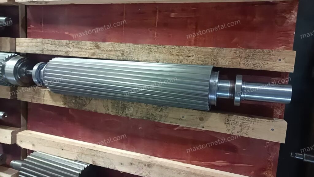
사출 성형에는 깔끔하게 공급되고 균일하게 용융되며 매 샷마다 일관되게 계량되는 펠렛이 필요합니다. 이는 엄격한 펠렛 길이 제어, 미분(fines) 및 꼬리(tails) 발생 최소화, 펠렛 중량 및 유변학적 특성(rheology)의 낮은 편차를 의미합니다. 스트랜드 라인은 용융물 이송 및 다이, 수조, 탈수, 커터 등 여러 공정 단계에서 각각 고유한 공차와 드리프트가 발생하기 때문에 변동이 생깁니다. 따라서 펠렛 균일성을 안정화하는 것은 단일 매개변수 조정이 아닌 시스템 전체의 작업입니다.
본 튜토리얼에서는 약 60% CaCO3 및 높은 재활용 원료 함량을 가진 PP/PE용 수조 스트랜드 펠레타이징 설비에서 가장 중요한 조절 요소를 조정하는 방법을 다룹니다. 간단한 공식과 신속한 점검을 통해 길이를 설정하고, 수조 크기를 결정하고, 절단 전 스트랜드를 컨디셔닝하며, 미분과 꼬리가 적은 깨끗한 절단면을 얻기 위해 나이프 간격과 압력을 설정하는 방법을 배우게 됩니다.
핵심 요약
- 펠렛 균일성을 하나의 체인으로 취급하십시오: 안정적인 용융 및 다이 → 적절한 냉각 및 난류 → 표면이 건조된 스트랜드 → 날카롭고 올바르게 설정된 나이프가 장착된 동기화된 커터.
- L = V ÷ (S × N) 공식을 사용하여 목표 펠렛 길이를 설정하고 온라인 측정으로 검증하십시오. 라인 속도와 나이프 수로부터 커터 RPM을 역산하여 구합니다.
- 체류 시간을 기준으로 냉각 경로의 크기를 결정하고 조정하십시오. 절단 전 안전한 스트랜드 온도에 도달할 수 있도록 수조 온도, 난류 및 길이를 조절합니다.
- 약 60% CaCO3가 함유된 마모성이 높은 PP/PE의 경우, 인성이 높고 내마모성이 우수한 나이프 재질로 시작하고 날 끝을 날카롭고 평행하게 유지하기 위해 엄격한 재연마 SOP를 도입하십시오.
- 미분, 꼬리 발생률, 펠렛 길이 범위 및 100개 펠렛 중량 CV의 추세를 파악하십시오. 변화를 특정 조정 작업과 연계하여 확신을 가지고 반복 개선할 수 있습니다.
사양 목표 및 KPI
치수 공차 및 L:D
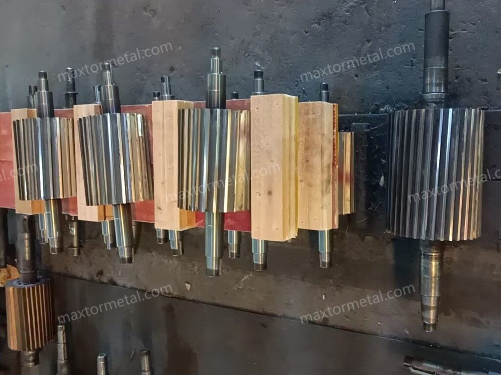
목표치 주변의 좁은 펠렛 길이 범위(예: 공장 시작 기준으로 ±0.2 mm)를 목표로 하십시오. 사출 성형 시 일관된 용융 및 스크류 이송을 지원하기 위해 길이 대 직경(L:D) 비율을 1:1에 가깝게 유지하십시오. 샘플링 프로토콜:
- 초도품: 3개의 스트랜드에서 50개의 펠렛을 측정하고 평균, 최소-최대 및 범위를 기록합니다.
- 안정화: 변경 후 첫 1시간 동안은 15분마다 반복합니다.
- 일상 점검: 매시간 스팟 체크 또는 로트별 점검 중 더 엄격한 기준을 적용합니다.
라인 속도와 커터 RPM 동기화, 다이 스트랜드 직경 편차 또는 절단 전 냉각 충분 여부를 점검하여 드리프트 원인을 파악하십시오. 용융 및 공급 품질을 최종 펠렛과 연계하는 방법론적 배경은 Plastics Technology의 압출기에서 펠레타이저까지 — 품질에 미치는 영향(From Extruder to Pelletizer — Influences Quality)에 수록된 업스트림 영향에 대한 시스템 관점을 참조하십시오. 품질에 미치는 시스템 영향.
미분 및 꼬리 허용 한계치
중량 대비 1% 미만의 미분과 신속한 육안 측정 기준 0.5% 미만의 꼬리 발생률을 실용적인 시작 목표로 설정하십시오. 100–200 g 샘플과 표준화된 체 가름(sieve) 방법을 사용하여 미분을 측정하고, 결과의 재현성을 위해 체 세트 및 메시 크기를 기록하십시오(예: ISO 3310 또는 이에 준하는 현지 표준을 준수하는 시험용 체 사용). 꼬리는 일반적으로 무뎌진 나이프, 부적절한 나이프와 베드 간격, 또는 여전히 너무 뜨겁거나 젖은 상태의 스트랜드 절단으로 인해 발생합니다. Plastics Technology는 트러블슈팅 개요에서 일반적인 근본 원인과 해결 방안을 설명합니다: 7가지 일반적인 펠레타이징 문제.
중량 CV 및 유변학적 특성 점검
100개의 펠렛 무게를 측정하고 변동 계수(CV = 표준편차 ÷ 평균)를 계산하십시오. 안정성 지표로서 한 자릿수 초반의 CV가 합리적인 시작 목표입니다. 테스트를 거쳐 자체 사양을 확정하십시오. 이를 가끔씩 실시하는 용융 흐름 지수(MFR) 또는 유변학적 특성 스팟 체크와 병행하여 스트랜드 안정성에 영향을 미칠 수 있는 용융 이력의 변화를 감지하십시오. MFR 값을 내부적으로 또는 고객에게 공표하는 경우, 해당 방법을 확립된 표준(예: ISO 1133 또는 QA 계획에서 합의된 동등한 방법)과 연계하십시오. 수지 제조업체 문서에는 펠렛 균일성 KPI를 명시하지 않더라도 테스트 방법(예: ISO 1133)이 설명되어 있습니다. 예를 들어 Borealis의 가공 데이터 컨텍스트를 참조하십시오: PP 가공 및 테스트 참조 자료.
용융물 이송 및 다이 제어
펌핑, 여과, 다이 기하학적 구조
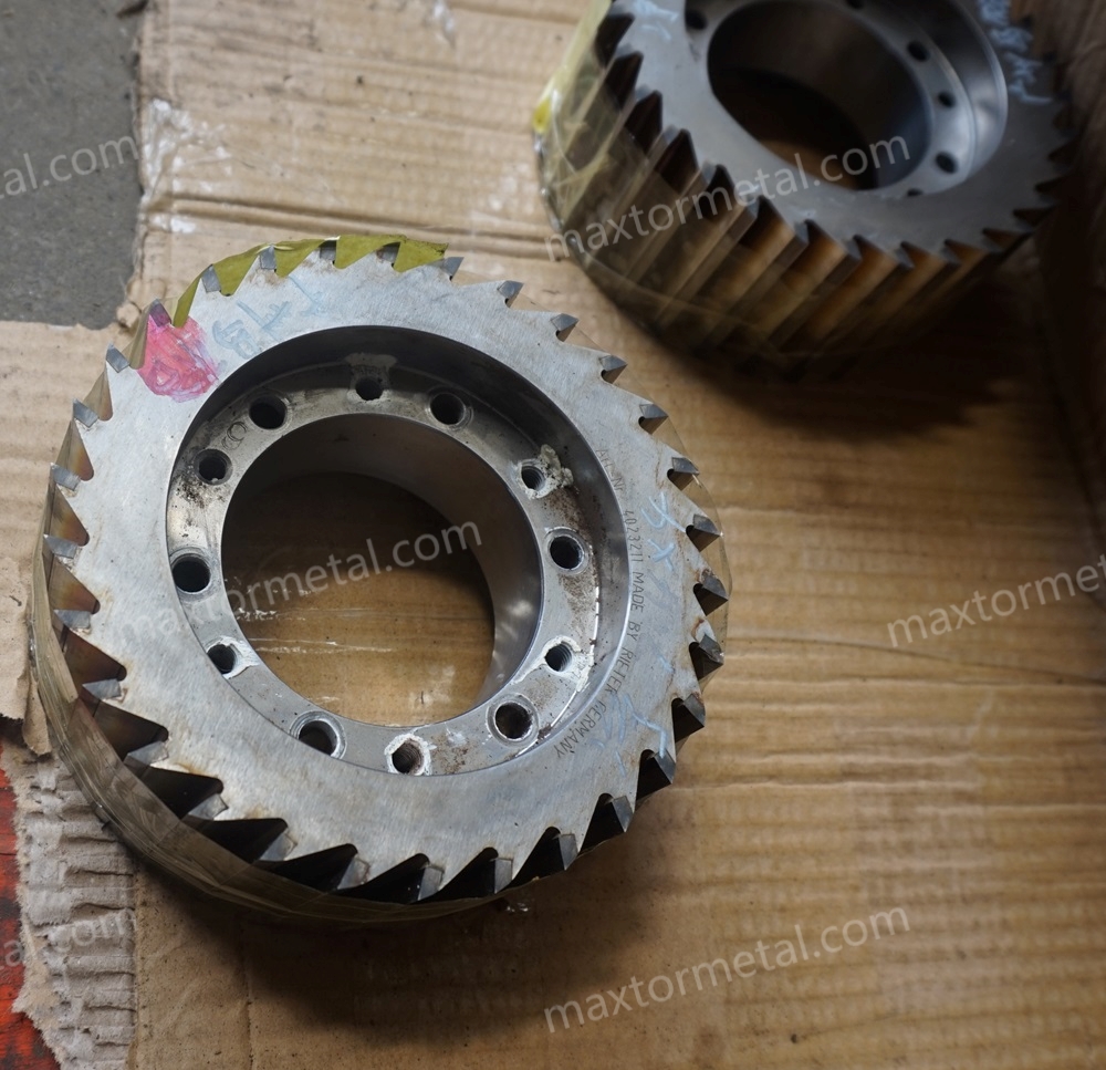
균일한 펠렛 크기는 안정적인 부피 이송에서 시작됩니다. 다음 사항을 확인하십시오:
- 펌프/압출기 출력 안정성: 모터 부하 및 용융 압력의 추세를 모니터링하여 부드럽게 작동하는지 확인합니다.
- 깨끗하고 적절한 스크린 팩: 재활용 원료로 인해 겔이나 이물질이 유입되는 경우 여과 단계를 높이십시오.
- 일관된 스트랜드 직경을 생성하는 다이 기하학적 구조: 불균일한 연신(drawdown)을 유발하는 혼합 인서트 사용을 피하십시오.
이 단계에서의 모든 변동은 향후 펠렛 길이 편차 및 절단면 품질 저하로 나타납니다.
다이 열 균일성 및 무결성
다이 영역이 설정 온도를 긴밀하게 추적하는지, 다이 표면이 평평하고 손상이 없는지 확인하십시오. 핫스팟, 콜드 코너 또는 마모된 표면은 스트랜드 직경 편차와 국부적인 연화를 유발하여 꼬리 발생이나 뭉개진 절단을 초래합니다. 스트랜드가 지속적으로 구부러지거나 직경에 줄무늬가 생기는 경우, 다운스트림 해결책을 찾기 전에 다이 세척, 표면 재가공 또는 카트리지 교체를 우선적으로 수행하십시오.
고충전/재활용 원료 적용
약 60% CaCO3 및 고함량 재활용 원료가 포함된 PP/PE의 경우, 더 심한 마모와 간헐적인 단단한 이물질 발생이 예상됩니다. 실질적인 대처 방안은 다음과 같습니다:
- 다이 및 나이프 보호를 위한 여과 정밀도 향상.
- 스트랜드 네킹 현상을 줄이기 위해 용융 온도를 약간 낮추고 인취 속도를 안정적으로 유지.
- 스트랜드의 타원형 변형 여부를 수시로 육안 점검하고, 다이 볼트 토크와 존(zone) 밸런스를 조정하여 토출 흐름을 균일하게 유지.
전단(업스트림) 공정에서의 결정이 후속 절단 품질에 미치는 영향에 대한 종합적인 시스템 관점은 위의 동일한 Plastics Technology 개요를 참조하십시오. 품질에 미치는 시스템 영향.
수처리 시스템 및 냉각 경로
수조 온도 및 난류
PP/PE의 경우 보수적인 수온 시작점(보통 약 40 °C 미만)을 설정한 후, 스트랜드 표면 온도와 절단 품질을 측정하여 검증하십시오. 초기 난류 형성은 경계층을 제거하고 열전달을 촉진하는 데 도움이 됩니다. 펠릿에 융착(fusion)이나 스미어(smear) 현상이 발생하는 경우, 체류 시간을 늘리거나 수조 온도를 낮추거나 난류를 추가/교반하십시오. 실질적인 냉각 용량 관련 정보는 냉각 극대화에 관한 Plastics Technology의 기술 조언에서 다루고 있습니다: 냉각 용량 개선.
냉각 시간 및 수조 길이
체류 시간을 기준으로 수조 크기를 설계하고 조정하십시오. Plastics Technology에서 제시하는 간편한 방법은 열전달 차트에서 냉각 시간을 도출하는 것입니다. 그 후:
- t = 냉각 시간 (s)
- V = 스트랜드 속도 (m/min)
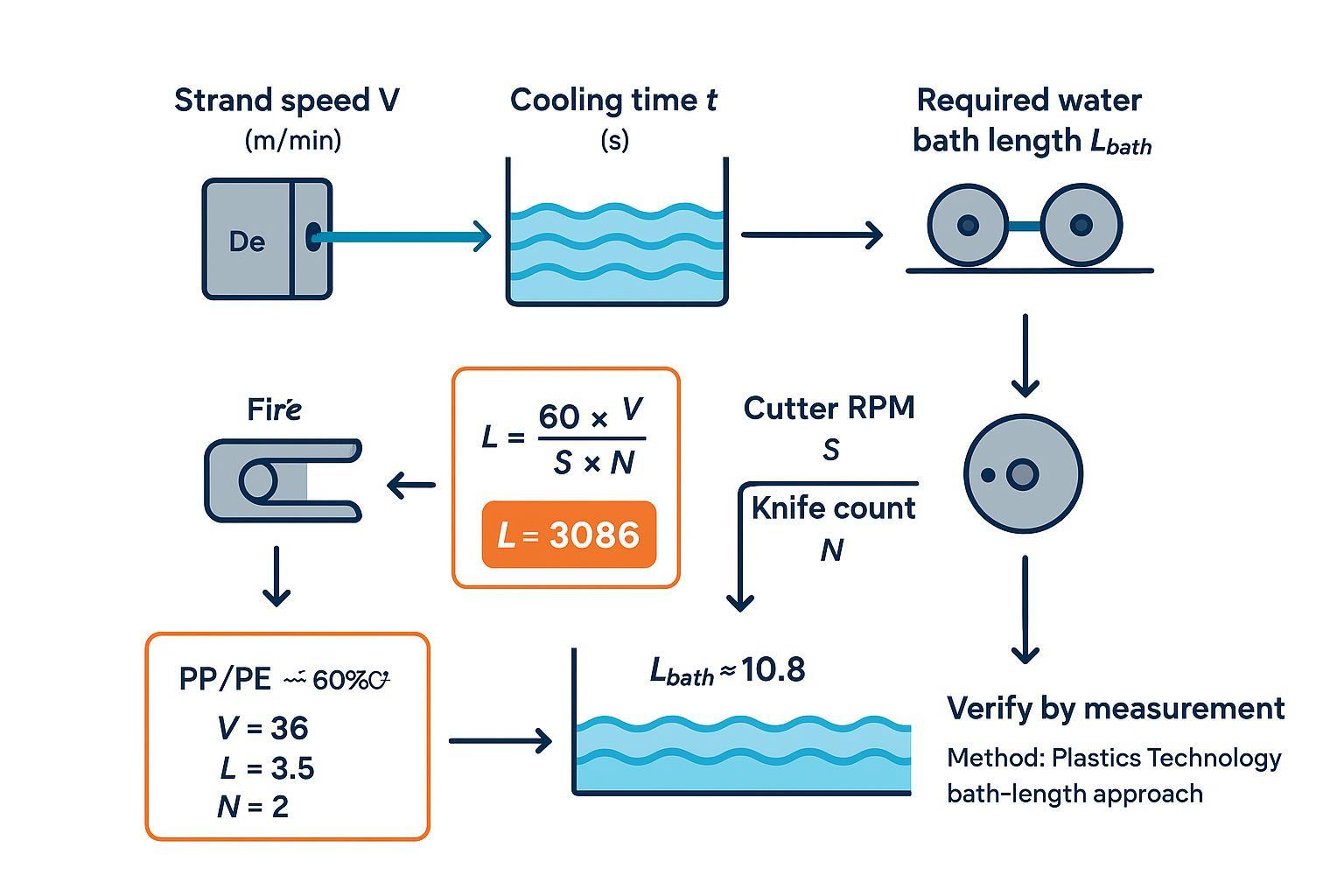
- Lbath = V × t ÷ 60 (m)
검증 체크리스트 (계산 수치가 실제 절단 품질로 구현되도록 보장):
- Measure strand surface temperature at the cutter entry and record the point and instrument used.
- If you see smear/fusion, treat it as a cooling/drying verification failure first (temperature + surface water), then adjust bath temperature/turbulence/effective length.
- When you change bath conditions, re-check pellet faces and tails incidence within 10–15 minutes.
Worked example for our water strand pelletising setup (PP/PE with ~60% CaCO3):
- Assume V = 36 m/min (after puller stabilises)
- From the PT method for a representative PP case, t ≈ 18 s as a starting estimate
- Lbath ≈ 36 × 18 ÷ 60 = 10.8 m
Validate on-line: if cut faces smear or pellets fuse, either lower the bath temperature, increase turbulence, or extend effective path (e.g., double-back) to add residence time. The full method for estimating cooling time and bath length is described in Plastics Technology’s guide: bath length determination.
Dewatering and pre-cut dryness
Right before the cutter, strands should be surface‑dry and at a temperature safely below the softening point. Practical tools include an air knife, a vacuum slot, or a compact suction hood. In special high-throughput or sensitive recipes, a small centrifugal pre‑dryer upstream of the cutter can help, though that’s more common after cutting. There’s no authoritative moisture number to hit; your acceptance criterion is visual and tactile: no visible film or droplets, strands don’t slip on feed rolls, and cut faces look crisp.
커터 설정 및 나이프 메커니즘
Pellet length vs line speed & RPM
Pellet length equals the distance a strand travels between successive cuts. If the cutter runs at S RPM with N knives on the rotor, cuts per minute are S × N. With line speed V (m/min), the pellet length L (mm) is the strand travel per cut:
- L (mm) = 60 × V ÷ (S × N)
Quick unit checks before you trust the number:
- Keep V in m/min (not m/s) and S in RPM.
- Confirm N is the number of active knives (not installed spares).
- After any change to V, S, or N, re-measure pellet length (don’t rely on the setpoint).
Two quick reverse-solves for PP/PE + ~60% CaCO3 at target L = 3.5 mm:
- Given V = 36 m/min and N = 2 knives:
- S ≈ 60 × 36 ÷ (3.5 × 2) ≈ 3086 RPM
- If you switch to N = 3 knives at the same speed and length:
- S ≈ 60 × 36 ÷ (3.5 × 3) ≈ 2057 RPM
Use these as setpoints, then measure 50 pellets and trim S until the mean length sits on target with a tight range. For broader system context on selecting and operating pelletising systems, see this overview: selecting the right pelletising system.
Knife clearance and pressure
Set the rotor-to-bed relationship method‑first, as absolute clearances and forces are model‑dependent. A practical SOP:
- Mount sharp knives; clean and inspect the bed knife face.
- Zero the adjustment using your machine’s fine adjusters; verify parallelism across the full width with dial indicators or feeler gauges.
- Nudge towards minimal clearance per OEM guidance. Where permitted, use a controlled “witness mark” technique to confirm a continuous, faint contact trace, then back off slightly. If the OEM forbids contact, rely on indicators and cut‑face inspection.
- Start with light contact pressure; run a short cut and inspect pellets under good light. Clean, square faces with no smearing or feathering indicate you’re close. Tails or fines call for re‑sharpening or slight clearance/pressure tweaks.
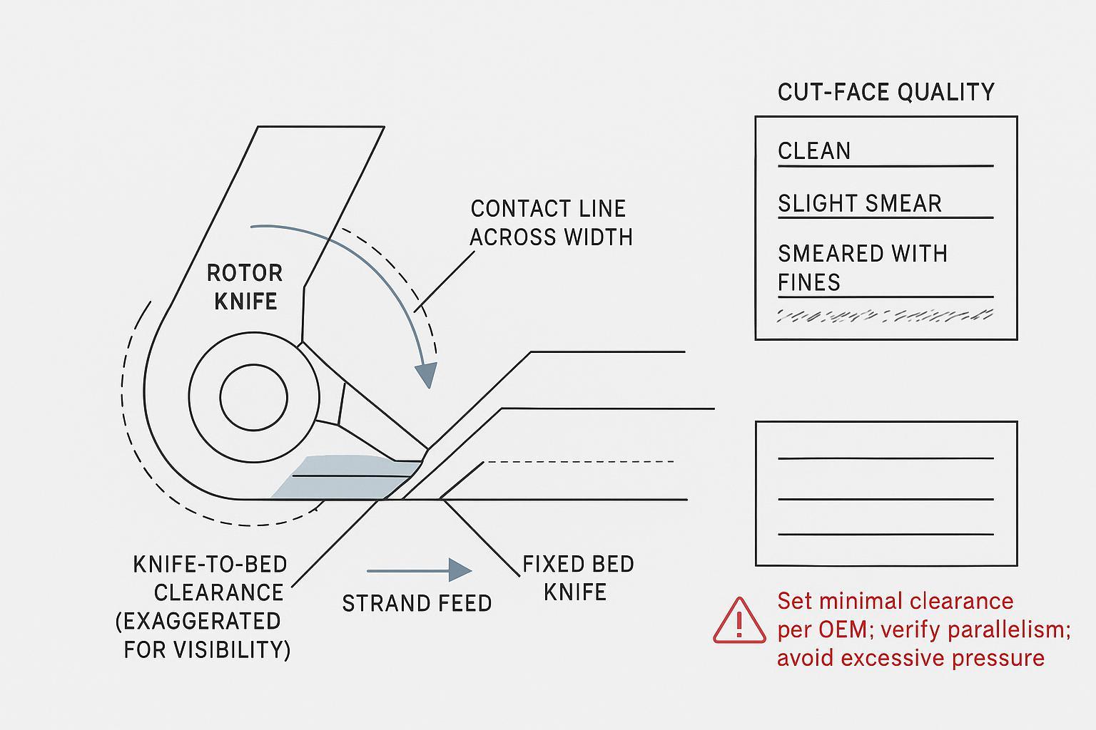
If you need a conceptual refresher on knife adjustment mechanisms seen on industrial strand pelletisers, OEM literature confirms the availability of fine adjusters and gap‑setting features: for instance, see a general product description referencing adjustment mechanisms: gap setting mechanisms in strand pelletisers.
Knife materials, wear, regrind SOP
Abrasive fillers like CaCO3 accelerate wear and can round the edge quickly. Choose materials and heat treatments with enough wear resistance for your duty, then protect geometry with a disciplined regrind plan.
Material comparison for PP/PE with ~60% CaCO3 (starting guidance):
- D2/SKD11 tool steel: typically hardened into the high‑50s to low‑60s HRC; good cost‑to‑resistance balance; tough enough for occasional contamination.
- M2 high‑speed steel: harder (low‑ to mid‑60s HRC) with better hot‑edge retention; can be more chip‑prone under impact.
- Carbide or carbide‑tipped: highest abrasion resistance (effective >65 HRC equivalent); more brittle; best when contamination risk is low and uptime demands are high.
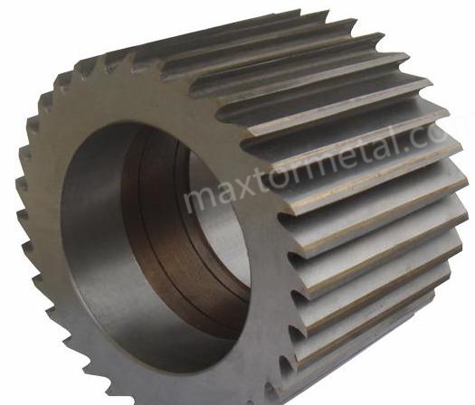
For background on materials and selection logic, see an industry overview: guide to pelletiser knives and materials. For a neutral supplier example with documentation support on materials, hardness and tolerances, you can review MAXTOR METAL’s resources such as the plastic pelletiser knife product page and their industrial blade tolerance guide. Where you need a deeper dive into materials trade‑offs, see an internal explainer on knife selection: pelletising knife selection guide.
Regrind SOP (outline)
- Inspection on removal: note edge radius, chips, burrs; record runout and flatness if specified by your OEM.
- Regrind to restore edge geometry within the OEM’s maximum stock‑removal allowance; keep faces flat and parallel; deburr carefully.
- Post‑grind checks: verify edge quality, flatness, and any runout limits; document results with hardness spot checks if required.
- Logging: track grind count per knife, installed date/time, and any adjustments needed to hit target pellet length and face quality after installation.
Documentation support—material certificates, hardness ranges, and tolerance reports—simplifies audits and reduces ambiguity at setup. Suppliers such as 맥스터 메탈 provide OEM/ODM‑fit knives with traceable material and inspection data; use such packs to align maintenance and QA without guesswork.
QA, 검증 및 트러블슈팅
Record template (copy/paste)
- Job ID / Line / Pelletiser model:
- Material / recipe notes (e.g., PP/PE + CaCO3 level, recycled content):
- Date / shift / operator initials:
Pellet length and synchronisation
- Line speed V (m/min):
- Cutter RPM S (RPM):
- Knife count N (active knives):
- Target pellet length L (mm):
- Measured pellet length (n=50): mean / min–max / range:
- Notes after adjustment (what changed, when, and why):
Fines and tails
- Fines sample mass (g):
- Sieve set / mesh sizes (ISO 3310 or equivalent):
- Sieve method (time, vibration setting, pre-cleaning notes):
- Fines mass (g) and fines % by weight:
- Tails visual check: sample size (n=200) / tails count / remarks:
Cooling and pre-cut conditioning
- Bath water temperature (°C):
- Effective bath length (m) / path (straight or double-back):
- Turbulence/agitation settings (what’s on, where):
- Dewatering method (air knife / vacuum slot / hood) and settings:
- Strand temperature at cutter entry: value / instrument / measurement point:
- Cut-face observation (crisp / smear / feathering) and action taken:
Knife condition and verification
- Knife material and batch/certificate reference (if available):
- Knife condition (new / reground) and grind count (if tracked):
- Clearance/parallelism verification tool (dial indicator / feeler gauge) and check points (left/centre/right):
- OEM setting method used (note any ‘witness mark’ policy allowed or forbidden):
Sampling and quick checks
- Pellet length: 50‑piece sample; report mean and range; adjust cutter RPM to centre the mean.
- Fines: sieve a 100–200 g sample; aim for low single‑digit percentages; if high, eliminate tails first, then address cooling and knife condition.
- Tails: visual tally on 200 pellets; if rising, inspect knife sharpness/clearance and strand conditioning.
- Weight CV: 100 pellets; compute CV; if drifting, verify die and puller stability.
- Rheology: occasional MFR checks to catch melt‑history shifts.
Link KPIs to moulding defects
- Tails: cause gate hang‑up, stringing, flow marks; reduce with sharp knives, correct clearance/pressure, and cooler, surface‑dry strands.
- Fines/dust: clog screw screens and nozzles; often secondary to tails; fix root cause and improve cooling/turbulence.
- Wide length spread: leads to variable shot packing; stabilise by synchronising V and S, locking strand diameter, and confirming bath residence time.
Fix tails, fusion, and dust
Prioritised corrective actions (work top‑down):
- Safety and confirmation: stop or slow to a safe speed; verify strand temperature and dryness; inspect knives.
- Knives and clearance: replace or regrind dull knives; re‑set minimal clearance with parallelism; adjust contact pressure incrementally.
- Cooling path: lower bath temperature, boost turbulence, or extend residence time; ensure early agitation.
- Synchronisation: re‑calculate RPM from L = 60 × V ÷ (S × N) and re‑centre the mean pellet length by measurement.
- Die and delivery: clean die face, confirm zone balance, check screen pack and melt stability.
For a wide‑angle troubleshooting view, Plastics Technology compiles common faults and remedies in its guidance on pelletising problems: troubleshooting overview.
Start with the stations that move the needle fastest: sharp knives set to minimal, parallel clearance; a cooling path that truly reaches safe strand temperature; and a synchronised cutter whose RPM matches your line speed and knife count. Verify each adjustment with short, disciplined checks—pellet length range, fines and tails, 100‑pellet weight CV—and keep notes so you can repeat success. For high‑fill and recycled PP/PE, lean towards tougher knife materials, plan more frequent edge inspections, and be ready to extend residence time or reduce bath temperature to protect cut quality. Then close the loop: measure, adjust one lever at a time, and confirm the result before you ramp. That’s how you lock uniform pellets that make injection moulding run smoothly.
저자 및 공개 정보
작가: 토미 탕 - 난징 METAL Industrial 수석 영업 엔지니어
경험: 12 years supporting industrial cutting applications (including pelletising and precision-ground blades)
자격증: CSE, CME, 식스 시그마 그린 벨트, PMP
면책 조항: Supplier and product references (including MAXTOR METAL) are provided as practical examples of documentation and material options. Always validate knife setting procedures and acceptance criteria against your pelletiser OEM manual and your site QA plan.
최종 업데이트: 2026-03-24
Change log: Added author credentials, disclosure, and standards/method anchors for measurement repeatability.

 English
  Spanish
  Italian
  French
  Portuguese
  Russian
  German
  Arabic
  Hindi
Hindi  Vietnamese
  Indonesian
  Japanese
  Korean