Lâminas trituradoras de gancho, conjuntos de facas trituradoras, trituradoras de gancho, lâminas trituradoras de eixo duplo, facas trituradoras circulares, lâminas trituradoras de 4 eixos
1. Lâminas para Trituradores Industriais: Especificações de Engenharia e Seleção
Este white paper baseia-se na experiência de fabricação da Maxtor Metal nos setores de trituração industrial, reciclagem e processamento de resíduos.
Este documento técnico estabelece as diretrizes de engenharia, os critérios metalúrgicos e os protocolos de fabricação para lâminas de trituradores de alto desempenho aplicadas em sistemas industriais pesados de reciclagem, gestão de resíduos sólidos e processamento de biomassa. Este white paper serve como referência central para gerentes de suprimentos, engenheiros mecânicos e especialistas em fabricação de equipamento original (OEM) que exigem uma vida útil previsível da ferramenta, alta retenção do gume e controle de falhas catastróficas com zero defeitos.
Key takeaway:
Maxtor Metal manufactures single-shaft and multi-shaft industrial shredder blades in AISI D2, DC53, H1.|3, M6V, and martensitic stainless steel grades, adhering to strict audit-ready quality and procurement protocolsfor every blade produced. Blades are vacuum hardened, cryogenically stabilized at −196℃, and precision-ground to tolerances as tight as ±0.01 mm for OEM compatibility with Weima, SSI, UNTHA, Vecoplan, and Andritz systems.
1.1 Technical Specifications Matrix
Parâmetro
Lâminas trituradoras de eixo único
Multi-Shaft Shredder Blades (Double/Four-Shaft)
Primary Blade Profiles
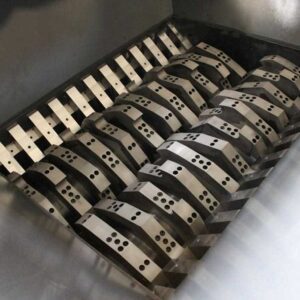
Multi-angle square concave rotary blocks, stator bed blades.
2. Visão Geral da Engenharia de Lâminas de Triturador
Industrial size reduction depends on two distinct mechanical shearing processes: high-frequency precision clipping and low-speed high-torque tearing. Understanding the mechanics of these operations is vital for predicting tool life and system efficiency.
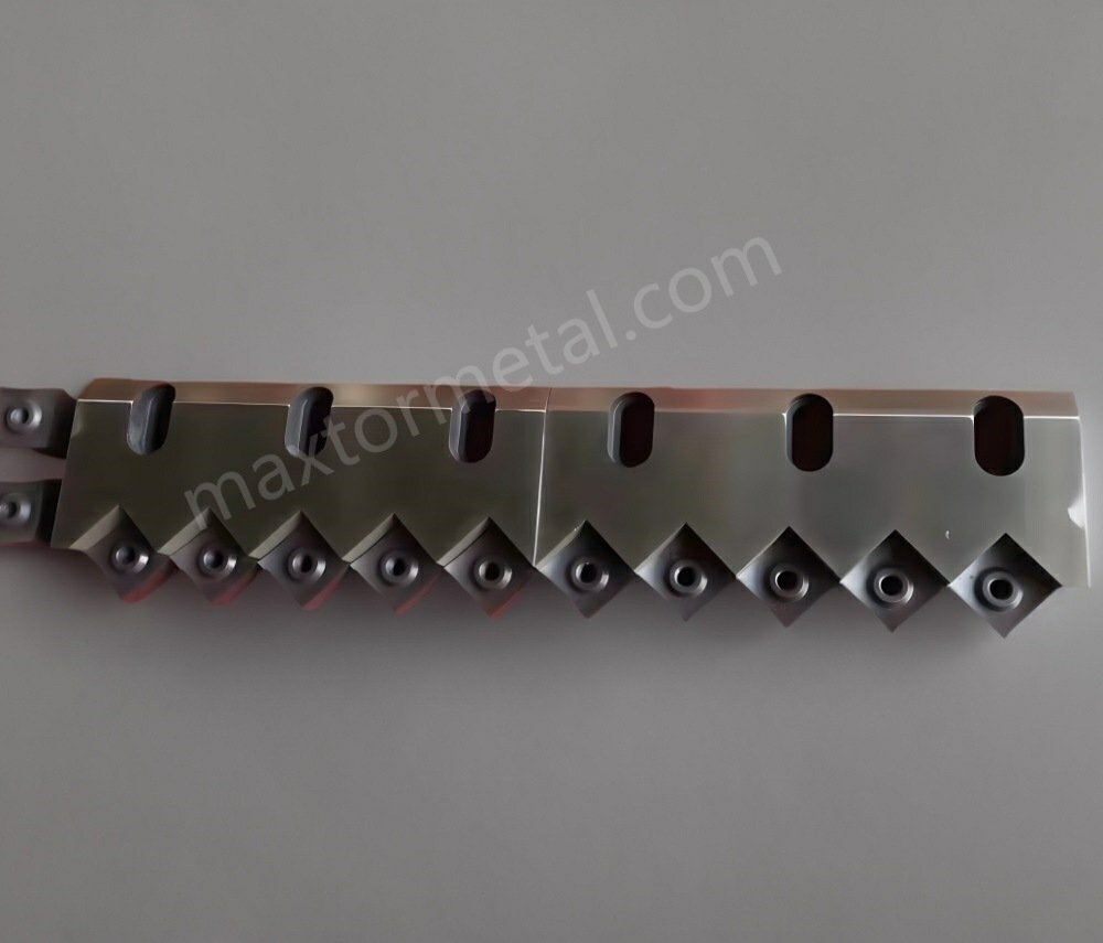
2.2 Multi-Shaft Tearing Dynamics
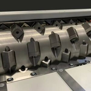
Multi-shaft industrial shredders (dual or quad-shaft configurations) operate via counter-rotating shafts turning at lower speeds but with high torque. The process relies on interlocking hook-like claw profiles that pull large, dense materials down into the center of the cutting chamber.
The shredding action uses a combination of hook tensile tearing, high-pressure lateral crushing, and interlocking side-face shearing. Rather than clean shearing, the mechanics focus on volumetric displacement and severe structural tearing. The open axial clearance system (0.15mm – 0.4mm side-gap per blade) permits independent thermal expansion and handles structural deformation under high loads.
2.1 Single-Shaft Cutting Dynamics
Single-shaft shredding systems run at higher rotational velocities, using a hydraulic ram to push bulk materials against a rotor turning at moderate-to-high speeds. The cutting mechanism is a precise, micro-gap scissor-like action occurring between the rotating square insert (rotary blade) and the stationary counter-knife (stator blade).
The primary stress applied to the material is pure shear stress, defined by:
$$\tau = \frac{F_{cutting}}{A_{shear}}$$
The dominant stress mode is shear, with the cutting force per unit shear area defined by τ = F/A. In practice, the narrow clearance (0.1–0.5 mm) also induces compressive stress normal to the shear plane, accelerating plastic deformation and clean fracture of the workpiece. The square concave profile of the rotary insert creates an acute positive rake angle that lowers the peak power needed from the main drive shaft. Final output particle size is strictly governed by a classification screen positioned beneath the rotor assembly.
2.3 Industrial Wear Characterization
Shredder blades operate in demanding tribological environments, with tool degradation following four distinct industrial wear patterns:
Abrasive Wear (Micro-Ploughing): Small, hard particles like sand, scale, glass fiber, or mineral dust slide across the tool steel matrix, cutting microscopic grooves and rounding the sharp cutting edges. This blunts the edge, increases power draw, and causes material pull-out or stretching instead of clean cutting.
Impact Fatigue (Chipping & Micro-Spalling): When heavy metallic impurities or uncrushable tramp components enter the machine, they exert high localized contact forces on the cutting edge. If the material’s fracture toughness (K1c) is insufficient, this contact stress causes immediate micro-chipping or catastrophic section failure.
Adhesive Wear & Thermal Softening: Processing dense polymers or highly elastic elastomers generates high friction at the cutting interface. This localized heat can cause localized temper-softening, which accelerates material loss and leads to polymer adhesion on the blade faces.
Intergranular Chemical Corrosion: Processing municipal solid waste, food waste, or animal tissue exposes the steel to high moisture, chlorides, organic acids, and salts (pH < 4). This reactive environment induces rapid pitting and intergranular oxidation, stripping the steel matrix of chromium and accelerating mechanical wear.
3. Aplicações de Lâminas para Trituradores Industriais
3.1 Advanced Plastics & Polymer Reclamation
Target Processing Machinery: High-throughput single-shaft shredders with variable-torque hydraulic rams.
Input Material Composition: Heavy-wall polyolefin pipes, injection-molded purges, automotive bumpers, and post-agricultural film contaminated with sand or soil.
Operational Engineering Criteria: High abrasive friction from glass fibers and mineral fillers. Requires excellent edge retention to prevent plastic film from stretching and wrapping around the rotor.
Recommended Specification: AISI D2 or DC53 rotary inserts through-hardened to 58–60 HRC. For heavy sand contamination, use an AISI 4140 base with brazed Tungsten Carbide (89–92 HRA) inserts.
Target Processing Machinery: High-precision, micro-clearance single-shaft granulators and shredders.
Input Material Composition: Armor-clad copper/aluminum power cables, communication lines, and electronic waste assemblies.
Operational Engineering Criteria: Requires precise, low-clearance cutting (0.1mm – 0.2mm) to cleanly separate copper strands from elastomer jackets without generating excess heat or insulation smear.
Recommended Specification: DC53 tool steel to prevent micro-chipping caused by hidden steel fasteners. Apply a physical vapor deposition (PVD) Titanium Nitride (TiN) coating (>2000HV) to the stator face to extend service life.
Target Processing Machinery: High-torque, low-speed dual-shaft or quad-shaft heavy industrial shredders.
Input Material Composition: Steel drums, structural automotive scrap, reinforced storage containers, and mixed hazardous waste containing structural steel plates.
Operational Engineering Criteria: Extreme shock loading and high torsion forces on the cutting claws when encountering thick uncrushable components.
Recommended Specification: AISI H13 (1.2344) or modified AISI A8 tool steel through-hardened to 48–54 HRC. This selection prioritizes high impact toughness and structural resistance over pure abrasive wear resistance to prevent blade shattering.
Operational Engineering Criteria: Severe combination of high abrasive friction from vulcanized rubber compounds and high tensile/shear loads from cutting high-carbon spring steel wire.
Recommended Specification: Special M6V vanadium-rich wear-resistant tool steel or premium DC53 hardened to 56–58 HRC to prevent claw breakage under wire tension.
Target Processing Machinery: High-torque quad-shaft shredder systems utilizing multi-claw configurations.
Input Material Composition: High-density baled agricultural straw, crop stalks, forestry residues, and wood pallets containing structural fasteners.
Operational Engineering Criteria: Fibrous biomass materials easily wrap around shredding shafts, creating high radial forces and friction. Hidden stones or metal wires can cause sudden impact loads.
Recommended Specification: AISI 4140 (1.7225) structural tool steel through-hardened to 48–54 HRC for standard operations requiring cost-effective toughness. For continuous RDF (Refuse-Derived Fuel) processing lines, upgrade to premium M6V vanadium steel.
3.6 Organic Municipal Waste, Food Waste & Animal Rendering
Input Material Composition: Post-consumer food waste with mixed cutlery/ceramics, whole animal carcasses, dense bone structures, and hooves from rendering operations.
Operational Engineering Criteria: Severe exposure to high-moisture organic acids, high salt concentrations, and continuous corrosive wear, combined with shock impacts from dense bone or mixed tableware.
Recommended Specification: For highly acidic food waste containing mixed ceramics/cutlery, use AISI 420 martensitic stainless steel hardened to 48–52 HRC. For pure carcass processing and animal rendering without heavy tramp metal, use high-carbon AISI 440C martensitic steel hardened to 58–60 HRC for high corrosion resistance and bone-shredding edge life.
4.Problemas de Falha Comuns e Soluções de Engenharia
4.1 Single-Shaft Tool Chipping from Tramp Metal
Root Cause Analysis: When uncrushable steel components (e.g., hardened bolts, structural brackets) enter a single-shaft shredder, they get trapped between the high-hardness rotary knife (58–60 HRC) and the stator bed. This sudden obstruction generates localized stresses that exceed the fracture toughness (K1c) of AISI D2 steel, causing severe edge chipping or body fracturing.
Engineering Redesign & Trade-offs: Replace AISI D2 with DC53 steel. DC53 features uniform, fine carbide structures that double the Charpy V-notch impact energy compared to traditional D2. Engineering Trade-off: Material costs increase by approximately 25%, but tool lifetime and resistance to catastrophic failure improve substantially.
4.2 Multi-Shaft Claw Fracture Under High Biomass Stress
Root Cause Analysis: Processing dense, fibrous biomass or agricultural straw bundles can cause long fibers to wrap tightly around the root of the cutter claws. This wrapping action wedges material between adjacent blades, creating high bending moments and tensile loads that can snap the claws off at the root.
Engineering Redesign & Trade-offs: Change the blade material from high-hardness D2 steel to high-toughness AISI H13 (1.2344) or a modified AISI A8 steel, heat-treated to 48–54 HRC. This shifts the steel matrix from a wear-focused carbide structure to a shock-resistant martensitic structure. Engineering Trade-off: Lowering the hardness reduces abrasive wear resistance, requiring more frequent edge sharpening to maintain throughput.
4.3 Inner Drive Bore Cracking via Wire EDM Residual Stress
Root Cause Analysis: Precise internal driven profiles (such as hex or octagonal shapes) are commonly finished using Wire Electrical Discharge Machining (EDM) after heat treatment. The high temperatures of the EDM process melt and re-solidify the steel surface, creating a microscale brittle “white layer” filled with residual tensile stresses. Under high torque, these internal corners act as stress concentrators, initiating cracks that propagate outward and split the blade.
Engineering Redesign & Trade-offs: Implement an immediate post-EDM low-temperature stress-relief temper at 180℃ – 200℃ for 4 hours to relieve the residual tensile stresses. Alternatively, upgrade the material to DC53, which can absorb these stresses without requiring special multi-step tempering steps.
4.4 Axial Expansion and Seizure of Multi-Shaft Assemblies
Root Cause Analysis: Processing dense materials over long, continuous runs generates high friction, heating the shredder blades up to 80℃ – 120℃. If the thermal expansion of the blades exceeds the original engineered axial clearances, the side faces of the interlocking cutters will grind against each other, leading to frictional lockup, shaft deflection, and gear drive overload.
Engineering Redesign & Trade-offs: Increase the thickness of the spacer collars relative to the blades, setting a single-side clearance gap of 0.15 mm to 0.40 mm (making the spacer 0.3 mm to 0.8 mm wider than the corresponding blade). Additionally, apply a -196℃ cryogenic treatment during heat treatment to eliminate retained austenite, ensuring high dimensional stability over a wide temperature range. Engineering Trade-off: Larger clearance gaps can allow thin sheet materials to pass through without being fully shredded.
4.5 Rapid Chemical Corrosion and Edge Softening in Biomass Processing
Root Cause Analysis: Processing organic food waste or animal carcasses releases high-moisture organic acids and chlorides (pH < 4). Standard cold-work tool steels like AISI D2 or DC53 lack sufficient free chromium, causing them to form iron oxides and pit rapidly under these conditions. This corrosion compromises the steel matrix, accelerating mechanical wear and causing the cutting edge to dull quickly.
Engineering Redesign & Trade-offs: Upgrade the cutter material to AISI 420 martensitic stainless steel (hardened to 48–52 HRC) or AISI 440C high-carbon stainless steel (hardened to 58–60 HRC), depending on the amount of mixed tramp metal present. Engineering Trade-off: Stainless tool steels are more difficult to precision-grind, increasing manufacturing costs and lead times.
4.6 Single-Shaft Rotary Blade Seating Loosening
Root Cause Analysis: High-frequency cutting forces apply cyclic, pulsing loads to single-shaft rotary inserts. If the dimensional tolerance between the insert’s bottom seating face and the rotor’s machined pocket exceeds 0.05 mm, the insert can shift micro-axially during operation. This movement puts high cyclic shear stresses on the central fastening bolt, leading to bolt fatigue and eventual failure.
Engineering Redesign & Trade-offs: Tighten the dimensional tolerances on the blade’s bottom seating and locator faces to a strict ±0.02mm via precision grinding. Engineering Trade-off: Requires high-precision CNC grinding fixtures, which increases tool manufacturing costs.
4.7 Severe Abrasive Edge Rounding from Glass-Fiber Reinforced Polymers
Root Cause Analysis: Glass fibers (GF) used in engineering plastics act as high-hardness abrasives during shredding. When these fibers slide across standard tool steel, they cause micro-ploughing that rapidly rounds the sharp cutting edge. Once rounded, the blade can no longer cut the plastic cleanly, increasing power consumption and generating friction that melts the polymer.
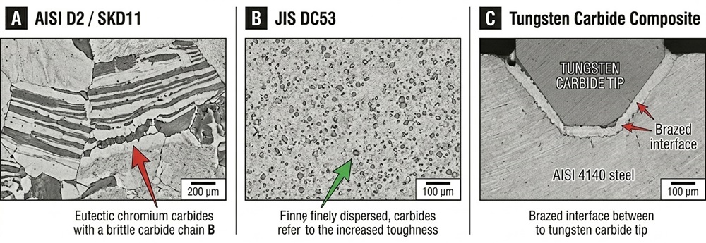
Engineering Redesign & Trade-offs: Use composite blades featuring an AISI 1045 or 4140 structural steel body with brazed Tungsten Carbide (WC-Co) inserts at the cutting edges. The carbide inserts provide high hardness (89–92 HRA) to resist fiber abrasion, while the steel body maintains structural toughness. Engineering Trade-off: High-vibration environments or tramp metal impacts can cause the brittle carbide inserts to crack or debond from the steel base.
4.8 Premature Corner Chipping on Square Concave Inserts
Root Cause Analysis: The four corner tips of single-shaft square concave inserts concentrate stress during operation. If the concave radius is ground too deep, the resulting edge geometry becomes too fragile, making the corners prone to micro-chipping under standard impact loads.
Engineering Redesign & Trade-offs: Optimize the grinding geometry by reducing the concave depth and introducing a small, controlled 0.1 mm chamfer or hone to the cutting edge. This reinforces the corner geometry with minimal impact on overall cutting sharpness.
4.9 Frictional Galling on Multi-Shaft Interlocking Faces
Root Cause Analysis: When shredding ductile materials like aluminum alloys or soft polymers, high lateral pressures can force the material into the side gaps between interlocking blades. This trapped material undergoes high friction and pressure, leading to localized cold-welding and material transfer (galling) onto the blade faces, which increases torque and friction.
Engineering Redesign & Trade-offs: Precision-grind the blade side faces to a smooth surface finish of Ra< 0.8μm to reduce friction. For highly ductile applications, add shallow radial escape grooves across the blade faces to help eject trapped particles. Introduce radial scraper fins onto the side profiles of the blades to help eject fine particles from the gap.
4.10 Thermal Cracking (Heat Checking) from Continuous Friction
Root Cause Analysis: Shredding highly elastic materials can generate high continuous friction, creating localized thermal gradients across the blade edge. The resulting cyclical thermal expansion and contraction can cause microscale thermal cracks (heat checking) perpendicular to the cutting edge, which can lead to larger structural failures.
Engineering Redesign & Trade-offs: Select tool steels with high thermal conductivity and temper resistance, such as AISI H13. Ensure the shredding system uses an automated reverse cycle or external cooling to manage operating temperatures.
5.Guia de Engenharia de Materiais
Selecting the proper steel alloy requires balancing three conflicting properties: wear resistance, impact toughness, and manufacturability (grindability).
5.1 Metallurgical Matrix Comparison
The following alloy comparison reflects Maxtor Metal’s qualified material library for shredder blade production.
International Alloy Standard
Primary Microstructural Carbides
Charpy V-Notch Impact Energy (Toughness)
Abrasive Wear Resistance
Machining & Grindability Index
AISI D2 / DIN 1.2379 / SKD11
Large, banded eutectic chromium carbides (Cr7C3).
Low (20 – 25 J/cm2).
High.
Difficult; high wheel wear.
DC53 (Premium Cold-Work)
Fine, evenly dispersed secondary alloy carbides.
Very High (28 – 45 J/cm2).
Excellent.
Fair; superior to D2.
AISI H13 / DIN 1.2344
Fine vanadium/molybdenum carbides.
Exceptional (50 – 80 J/cm2).
Moderate.
Good; high machinability.
AISI A8 Mod (Toughness Tool)
Balanced chromium/molybdenum matrix.
Excellent (80 – 100J/cm2).
Medium-High.
Fair.
M6V (High-Vanadium Tool)
Ultra-hard vanadium carbides (VC, 2800HV).
Moderate-High (35 – 40J/cm2).
Superior long-life.
Difficult; requires specialized wheels.
AISI 4140 / DIN 1.7225
Homogeneous tempered martensite (no primary carbides).
High structural ductility.
Low; requires base support.
Excellent; low manufacturing cost.
AISI 420 / DIN 1.4021
Dispersed chromium carbides in a stainless matrix.
High (60 – 80J/cm2).
Medium.
Good.
AISI 440C / DIN 1.4125
High-density primary chromium carbides.
Low-Moderate (15 – 22J/cm2).
High.
Difficult.
Tungsten Carbide (WC-Co)
Pure sintered Tungsten Carbide grains.
Brittle; low impact threshold.
Maximum Industrial.
Requires diamond grinding.
Impact energy values are measured at target working hardness after vacuum hardening and triple tempering. Values at annealed state are significantly higher and are not representative of service conditions.
5.2 Advanced Metallurgical Selection Guidelines
5.2.1 AISI D2 vs. DC53
Traditional D2 steel contains large, non-uniform chromium carbides that form during solidification. These carbides act as stress concentration sites where micro-cracks can easily initiate under heavy shock loads. In contrast, DC53 modifies the chemical composition to eliminate these large carbide bands, resulting in a fine, uniform carbide distribution. This microstructural improvement doubles the material’s impact toughness while maintaining equivalent or superior wear resistance at high hardness levels (58–60 HRC).
M6V: Contains high amounts of vanadium, which forms ultra-hard vanadium carbides throughout the matrix. This alloy is ideal for high-volume, continuous processing lines like RDF generation, where long tool life is critical to reducing downtime.
AISI 420 & 440C: These martensitic stainless steels are selected for highly corrosive applications. AISI 420 provides the impact toughness needed to handle mixed municipal waste containing occasional hard impurities. AISI 440C features higher carbon and chromium content, providing excellent edge retention and wear resistance for pure organic processing, such as animal carcass rendering.
6. Tratamiento Térmico e Equilíbrio de Dureza das Lâminas
Industrial shredder blades require precise heat treatment to achieve the proper balance of hardness and toughness. Incorrect tempering or incomplete phase transformation can lead to premature tool failure.
6.1 Vacuum Austenitizing & Controlled Quenching
Blades are heat-treated in a high-vacuum furnace (10-4mbar) to prevent surface decarburization and oxidation. For premium tool steels like D2 and DC53, the material is preheated in stages to minimize thermal distortion before being brought to its final austenitizing temperature (1020℃ – 1040℃). Once uniform carbon dissolution is reached, the parts undergo a high-pressure gas nitrogen quench (6 – 10bar) to quickly transform the austenite matrix into hard martensite.
6.2 Deep Cryogenic Transformation Process
Following the quench, the steel matrix can retain up to 5% to 15% unstable retained austenite. To ensure long-term dimensional stability and prevent distortion or cracking under heavy structural loads, blades undergo a deep cryogenic treatment:
The temperature is lowered at a controlled rate (1℃/min) down to -196℃ using liquid nitrogen.
The blades are held at -196℃ for 12 to 24 hours.
This process forces the complete transformation of retained austenite into martensite and promotes the precipitation of fine η-carbides, improving both wear resistance and structural stability.
6.3 Precision Tempering Strategies
Tempering modifies the hard, brittle martensitic structure into a tougher, more resilient tempered martensite.
High-Temperature Tempering (Secondary Hardening Window): For D2 and DC53 blades used in high-wear applications, triple tempering is performed at 520℃ – 540℃. This triggers secondary carbide precipitation, maximizing wear resistance while maintaining a stable hardness of 58–60 HRC.
Low-Temperature Tempering (Toughness Window):
For shredder blades utilizing AISI D2, tempering is conducted at 180℃ – 200℃ to relieve quenching stresses and achieve peak impact toughness while maintaining a high working hardness of 58–61 HRC. To prevent micro-cracking during subsequent Wire EDM for internal shaft bores, a mandatory post-EDM stress-relief temper at 180℃ – 200℃ for 4 hours must be enforced.
For multi-shaft claw configurations subjected to severe operational shock loads, AISI H13 items must undergo high-temperature tempering cycles within 550℃ – 580℃. This drives complete secondary transformation and matrix stress-relief, establishing a stable tempered martensite structure that delivers its peak Charpy impact energy while targeting a hardness of 48–54 HRC.
7. Geometria da Lâmina e Engenharia do Gume
The geometric design of a shredder blade determines its cutting efficiency, material throughput, and structural durability.
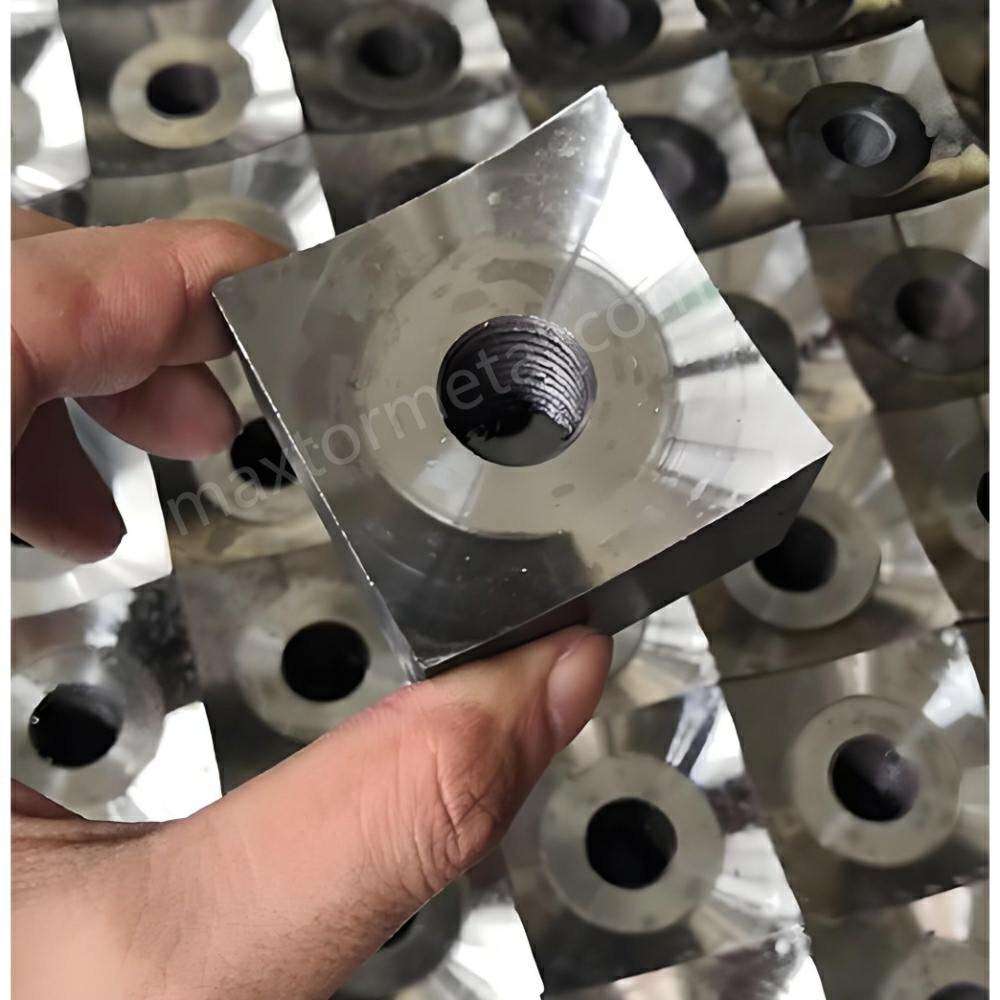
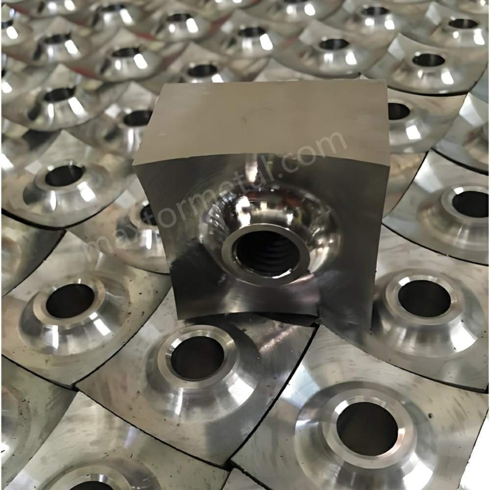
7.1 Single-Shaft Insert Architecture
Single-shaft rotary knives are typically designed as multi-angle square concave inserts. The concave face creates an aggressive, positive rake angle (α = +10°to +15°) that helps pull material into the cutting zone, lowering the required drive motor power.
The center of the insert features a precision-machined countersunk hole designed to accept high-tensile socket head cap screws, securing the blade tightly into its rotor pocket. This pocket provides multi-surface support to absorb high radial and axial cutting forces.
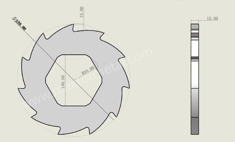
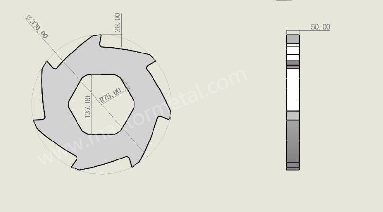
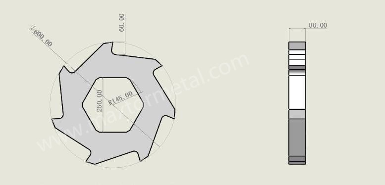
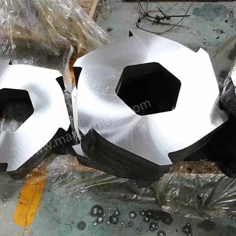
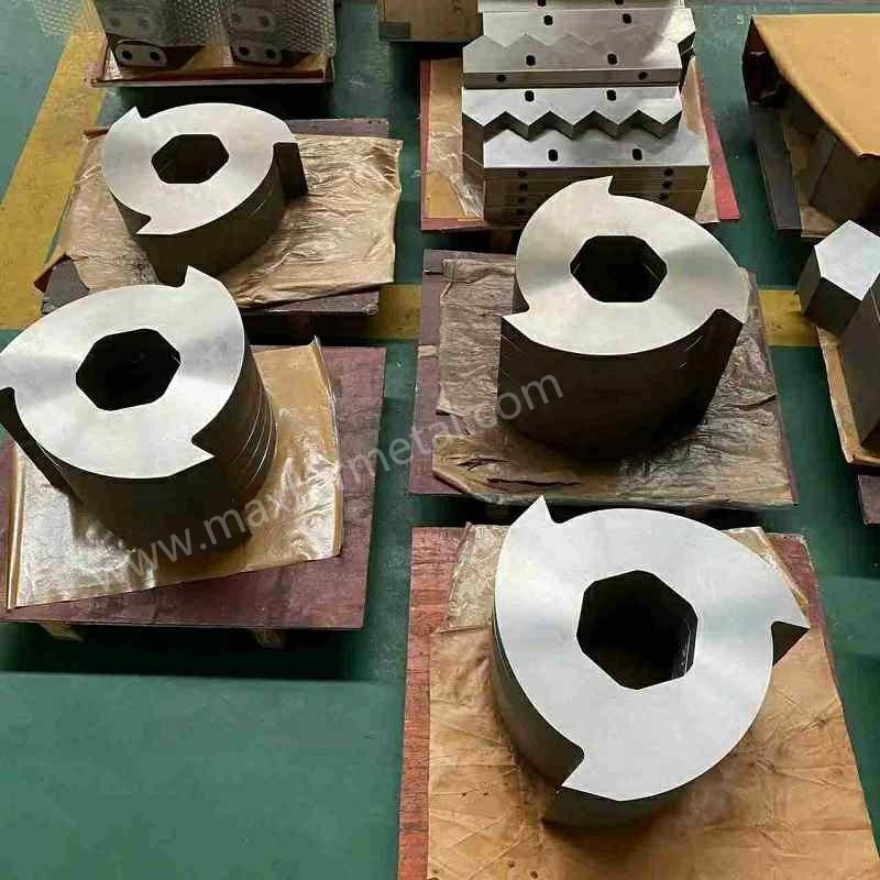
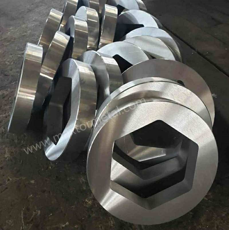
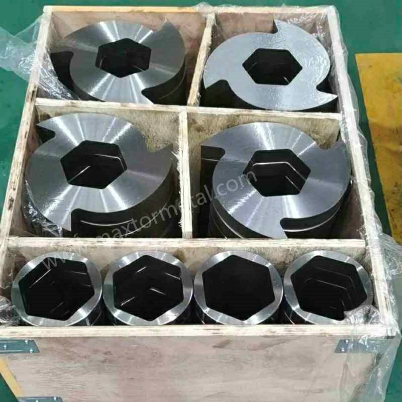
7.2 Multi-Shaft Claw Profiles and Bore Mechanics
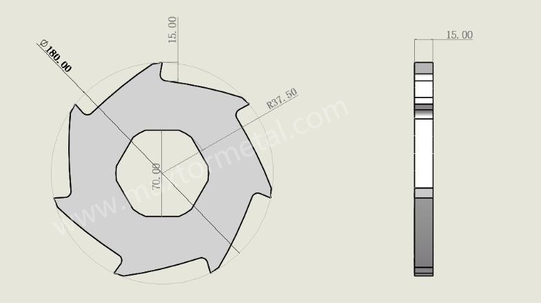
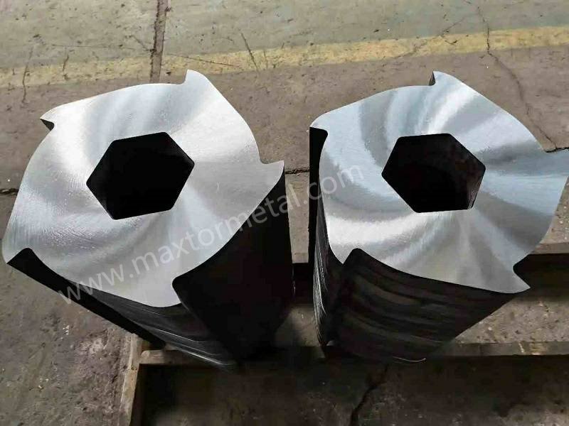
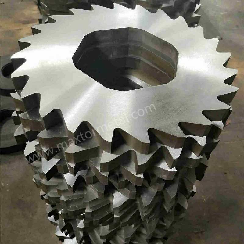
Multi-shaft blades are styled as disk cutters featuring a variable number of cutting claws (typically 3-claw, 5-claw, or 8-claw configurations).
3-Claw Profile: Features deep, aggressive hooks with a tall profile, making it ideal for grabbing and tearing bulky, hollow items like plastic drums or car body shells.
8-Claw Profile: Features shorter, closely spaced claws designed for high-density, uniform sizing applications, such as tire shredding or fine biomass processing.
The design of the internal drive bore is critical for delivering high torque from the main drive shaft:
Hexagonal / Octagonal Bores: Provide positive mechanical engagement but feature sharp internal corners that act as stress concentrators.
Involute Spline Bores: Feature a series of matching internal teeth that distribute torsional loads evenly across the entire circumference. This design significantly reduces localized stress concentration, making it ideal for heavy-duty recycling operations.
8. Processo de Fabricação e Inspeção de Qualidade das Lâminas
To ensure reliable performance in demanding recycling environments, shredder blades must follow strict, quality-controlled manufacturing stages.
8.1 Advanced Manufacturing Workflow
Maxtor Metal’s standard manufacturing sequence for industrial shredder blades follows eight controlled stages:
Material Sourcing & Forging: Use clean, vacuum-degassed tool steel ingots. Perform 3D multi-directional forging to ensure uniform grain structure and break up coarse carbide bands.
Spheroidized Annealing: Heat-treat to produce a uniform distribution of granular carbides within a soft ferrite matrix, ensuring consistent machinability and dimensional stability.
CNC Rough Machining: Mill the core blade profiles, drill countersunk holes, and rough-turn the outer diameter, leaving a uniform 0.3mm – 0.5mm grinding allowance across all critical faces.
Vacuum Heat Treatment & Cryogenic Stabilization: Execute the complete vacuum hardening, liquid nitrogen deep freeze, and triple tempering sequence to fix the material’s microstructural properties.
Precision Super-Grinding: Use specialized CNC surface grinders equipped with vitrified CBN (Cubic Boron Nitride) or diamond wheels to finish the cutting edges to a smooth surface finish of Ra< 0.8μm.
Wire EDM Profiling (For Complex Bores): Use high-precision wire EDM to cut internal hexagonal or spline bores into the hardened blade body.
Low-Temperature Stress-Relief Tempering: Immediately temper the parts at 180℃ – 200℃ for a minimum of 4 hours to eliminate residual tensile stresses and the brittle EDM “white layer”.
Final Quality Control Inspection: Validate all dimensions using automated Coordinate Measuring Machines (CMM).
8.2 Metrology Protocols & Inspection Tolerances
Every finished blade must pass three quality control checks before release:
End-Face Flatness Verification: Measured using an optical flat or high-precision digital indicator across the entire blade diameter. For high-precision applications, flatness variation must not exceed ±0.01mm.
Dual-Face Parallelism Testing: The thickness variation between opposing parallel faces is verified at four symmetric points. Total thickness deviation must remain within ±0.05mm to ensure uniform seating when blades are stacked together on a multi-shaft assembly.
9. Estudos de Caso
9.1 Case Study 1: Preventing Cracking in Industrial Silver Recycling
The following data comes from Maxtor Metal’s project support for a precious metals reclamation operator; the customer name has been anonymized.
Original Equipment Configuration: Multi-shaft heavy shredder using standard AISI D2 steel blades through-hardened to 60 HRC. Internal drive engagement was handled via a standard wire EDM-cut internal hexagonal bore.
Operational Failure Analysis: The original D2 blades frequently cracked and split from the sharp corners of the internal hex bore outward during early operation. Investigation revealed that the high torque required to process dense silver scrap amplified the residual tensile stresses left behind by the wire EDM process. The localized micro-cracking was heavily aggravated by the uncontrolled tensile stress fields generated during the legacy vendor’s post-EDM wire cutting, which omitted the critical stress-relief tempering protocol required to eliminate the brittle recast white layer. The large, brittle carbide structures typical of standard D2 steel could not absorb these combined loads, leading to rapid crack propagation and failure.
Evaluation of Engineering Solutions
Solution A: Upgrade to Material DC53
Engineering Approach: Replace AISI D2 steel with premium DC53 cold-work tool steel while maintaining standard, high-efficiency manufacturing methods.
Result Matrix: The fine, uniform carbide structure of DC53 doubled the material’s impact energy compared to D2. This increased toughness allowed the steel matrix to naturally absorb the residual stresses from the EDM process and handle the high torque loads without cracking. The blades maintained a high surface hardness of 58–60 HRC, preserving full wear life while shortening manufacturing lead times.
Solution B: Modify Manufacturing via a Four-Step Process
Engineering Approach: Maintain the original AISI D2 material but completely restructure the manufacturing sequence to isolate and relieve internal stresses:
Vacuum-harden the blank to a lower, tougher hardness level of 52 HRC.
Rough-grind both faces, leaving a 0.1mm – 0.2mm machining allowance.
Wire-EDM cut the internal hexagonal bore profile.
Perform a long, low-temperature stress-relief temper at 180℃ – 200℃ to relieve internal tensile stresses before a final finish grind.
Result Matrix: This process successfully prevented internal bore cracking and achieved a precise flatness tolerance of ±0.01mm. However, lowering the hardness to 52 HRC reduced the blades’ wear life by roughly 35%. This approach also significantly increased manufacturing costs, required more complex processing steps, and extended production lead times.
Final Implementation Decision: The operator chose Solution A. Upgrading to DC53 eliminated the cracking failures, maintained optimal edge wear life, simplified manufacturing, and reduced overall tool production times.
9.2 Case Study 2: Extending Tool Life in Corrosive Organic Waste Processing
The following data comes from Maxtor Metal’s project support for a municipal solid waste processing facility; the customer name has been anonymized.
Industrial Operator Profile: A municipal solid waste facility operating continuous organic waste and animal rendering lines.
Original Equipment Configuration: Heavy-duty dual-shaft shredder fitted with standard AISI D2 tool steel multi-claw blades.
Operational Failure Analysis: The original D2 blades showed severe surface rust and pitting corrosion within hours of processing acidic organic waste (pH < 4.5). This chemical corrosion quickly dulled the cutting edges, causing fibrous materials to wrap around the shafts and clog the machine. The resulting friction led to high operating temperatures, motor overloads, and frequent unscheduled maintenance shutdowns.
Implemented Engineering Redesign: The D2 blades were replaced with high-carbon martensitic stainless steel (AISI 440C), vacuum-hardened and low-temperature tempered to a stable 59 HRC. The side clearance gaps were also opened to 0.25 mm using wider, corrosion-resistant spacers to handle thermal expansion.
Quantified Performance Improvement: The upgraded AISI 440C stainless blades resisted organic acid pitting, maintaining a clean cutting edge over long runs. Continuous operating life between sharpening intervals increased from 72 hours to 300 – 580 hours depending on waste stream acidity and throughput rate. Frictional heat generation was significantly reduced, eliminating thermal clogging and lowering overall motor power consumption by 14%.
10. Seção de Perguntas Frecuentes (FAQ)
Por que o aço AISI D2 frequentemente lasca ou falha ao triturar resíduos sólidos urbanos mistos?
O AISI D2 contém grandes carbonetos de cromo não uniformes que se formam durante a solidificação. Essas bandas de carboneto são frágeis e atuam como concentradores de tensão interna. Quando o triturador encontra metais estranhos não trituráveis ou pedras pesadas, as cargas de impacto repentinas excedem a tenacidade à fratura da matriz D2, levando a micro-lascamentos ou grandes trincas no corpo da lâmina.
Como a atualização para o DC53 ajuda a evitar que as lâminas do triturador trinquem?
O DC53 reduz as grandes bandas de carboneto de cromo típicas do D2, substituindo-as por uma distribuição de carbonetos fina e uniforme. Com base nos testes de qualificação de materiais da Maxtor Metal, esse ajuste microestrutural aproximadamente dobra a energia de impacto Charpy com entalhe em V em comparação com o D2 padrão na mesma dureza de trabalho (58–60 HRC), permitindo que a lâmina absorva melhor impactos repentinos e alto torque sem se fraturar.
Qual é a folga lateral ideal para lâminas de triturador de múltiplos eixos e por que ela é necessária?
Com base nas especificações de montagem multi-eixo da Maxtor Metal, a folga lateral padrão por lado varia de 0.15 mm a 0.40 mm, sendo alcançada ao fabricar o anel distanciador de 0.3 mm a 0.8 mm mais largo do que a espessura da lâmina. Essa folga integrada acomoda as tolerâncias de espessura (ISO 2768-mK) e permite que as lâminas se expandam livremente conforme o atrito as aquece durante a operação, evitando travamento axial e engripamento.
Quando as pastilhas de carboneto de tungstênio devem ser usadas em vez de aço-ferramenta maciço para trituradores de eixo único?
As pastilhas de carboneto de tungstênio são ideais para aplicações de alta abrasão com baixo risco de forte impacto, como a trituração de filmes agrícolas contaminados com areia ou o processamento de plásticos de engenharia reforçados com fibra de vidro. As pastilhas de carboneto oferecem alta dureza (89–92 HRA) para resistir ao desgaste abrasivo, enquanto uma base de aço tenaz como o AISI 4140 fornece o suporte estrutural.
Por que o tratamento criogênico profundo (-196 °C) é recomendado para lâminas de trituradores de alta resistência?
O tratamento criogênico força a austenita retida instável a se transformar completamente em martensita estável. No protocolo de tratamento térmico da Maxtor Metal, as lâminas são mantidas a −196 °C por 12 a 24 horas após a têmpera, eliminando as tensões microestruturais residuais que poderiam causar empenamento ou distorção em serviço, e promovendo a precipitação de finos carbonetos secundários que melhoram a resistência geral ao desgaste.
O que causa a fissura nos furos internos de arrasto (hexagonais ou octogonais) e como isso pode ser corrigido?
O acabamento de furos internos de arrasto por eletroerosão a fio (wire EDM) cria uma "camada branca" fina e frágil na superfície do aço que contém altas tensões de tração residuais. Os cantos vivos dos furos hexagonais ou octogonais também concentram tensões naturalmente. Sob alto torque, as trincas podem se iniciar facilmente nesses cantos e se propagar para o exterior. Isso pode ser evitado aplicando um revenimento para alívio de tensões pós-EDM entre 180 °C e 200 °C ou atualizando o material da lâmina para o DC53 de alta tenacidade.
Qual material de lâmina é o melhor para processar resíduos alimentares orgânicos corrosivos?
For resíduos orgânicos que contêm alta umidade e ácidos, os aços inoxidáveis martensíticos AISI 420 ou AISI 440C são recomendados. O AISI 420 oferece boa tenacidade ao impacto para fluxos de resíduos mistos, enquanto o AISI 440C proporciona maior dureza (58–60 HRC) e excelente retenção de corte para aplicações de processamento de subprodutos (rendering) de grande volume, como o processamento de carcaças.
Qual acabamento de superfície é necessário para as faces das lâminas rotativas de eixo único?
De acordo com os padrões de retificação e inspeção da Maxtor Metal, a face de corte côncava deve ser retificada com precisão para Ra < 0.8 μm para manter um gume de corte afiado e de baixo atrito, enquanto os assentos de montagem planos exigem Ra < 1.6 μm para garantir um encaixe rígido e seguro no alojamento do rotor.
Por que os aços-ferramenta padrão são ineficazes para o processamento de subprodutos animais (rendering) e carcaças?
Os fluidos animais contêm altas concentrações de ácidos orgânicos e sais que fazem com que os aços-ferramenta padrão, como o D2 ou o DC53, enferrujem e sofram corrosão por pites rapidamente. Esse desgaste corrosivo degrada a matriz do aço e embota rapidamente o gume de corte, levando ao entrelaçamento do material, atrito e eventual sobrecarga da máquina. Aços inoxidáveis martensíticos como o AISI 440C são necessários para suportar essas condições.
Qual é a finalidade do revestimento PVD TiN em contra-lâminas (estatores) de eixo único?
O revestimento de nitreto de titânio (TiN) aumenta a dureza superficial para mais de 2000 HV nas faces de cisalhamento primárias. Esse revestimento atua como uma barreira contra o desgaste abrasivo, tornando-o altamente eficaz para aplicações de precisão, como a reciclagem de cabos elétricos, onde a manutenção de um gume limpo e afiado é crítica para evitar a deformação do isolamento.
Como o perfil de uma lâmina multi-eixo de 3 garras difere em aplicação de um perfil de 8 garras?
O perfil de 3 garras apresenta ganchos altos e agressivos projetados para agarrar e rasgar materiais volumosos e ocos, como tambores plásticos, pneus ou sucata automotiva. O perfil de 8 garras possui ganchos mais curtos e frequentes que realizam um rasgamento menos agressivo, porém entregam uma granulometria mais uniforme e fina, tornando-o ideal para processar biomassa solta ou borracha pré-triturada.
Por que as tolerâncias dimensionais para as bases das lâminas de eixo único são restritas a ±0.02 mm?
Os trituradores de eixo único operam com uma ação de corte pulsante de alta frequência. A Maxtor Metal aplica uma tolerância estrita de ±0.02 mm nos assentos da base da lâmina e nas faces de localização —verificada por meio de retificação CNC de precisão— para garantir um ajuste rígido dentro do alojamento do rotor e evitar micro-movimentos que causam falha por fadiga dos parafusos de fixação principais.
Quais compensações de engenharia ocorrem ao reduzir a dureza da lâmina para melhorar a tenacidade?
Reduzir a dureza de uma lâmina (por exemplo, revenindo o aço D2 para 52 HRC) aumenta sua tenacidade ao impacto e resistência a trincas. No entanto, isso reduz sua resistência ao desgaste abrasivo, o que significa que os gumes de corte perderão o corte mais rapidamente e exigirão afiação ou substituição mais frequentes, aumentando o tempo de inatividade operacional.
Qual é a vantagem de um furo estriado envolvente (involute spline) em relação a un furo hexagonal padrão para acionamentos multi-eixo?
O furo hexagonal concentra as tensões torcionais em seus seis cantos vivos, o que pode levar a trincas por fadiga com o tempo. Já o furo estriado envolvente utiliza uma série de dentes curvos para distribuir o torque de acionamento uniformemente por toda a circunferência do eixo, reduzindo significativamente o estresse localizado e prolongando a vida útil da lâmina sob cargas pesadas.
Como identificar se a falha de uma lâmina foi causada por desgaste abrasivo ou por fadiga por impacto?
O desgaste abrasivo manifesta-se como microrranhuras suaves, arranhões e um arredondamento gradual do gume de corte ao longo do tempo. A fadiga por impacto causa micro lascamento repentino, esfoliação (spalling) ou trincas grandes e denteadas em todo o corpo da lâmina, normalmente desencadeadas pelo impacto com um objeto não triturável.
Chamada para Ação de Engenharia Final
Otimize a Produtividade do seu Sistema de Trituração
Does your production line experience frequent downtime due to blade chipping, corner cracking, or rapid wear? Shifting from generic replacement parts to precision-engineered shredder blades can stabilize your processing costs and improve system reliability.
Maxtor Metal’s engineering team can review your system drawings and material requirements to develop customized solutions:
Custom Alloy Matching: We select and treat materials (including DC53, M6V, and AISI 440C) based on your specific waste stream dynamics.
Fabricação de precisão: All parts are finished with advanced vacuum heat treatments, cryogenic stabilization, and precision CNC grinding down to ±0.01mm tolerances.
Direct RFQ Support: Submit your CAD files (.STEP, .DWG) or OEM part numbers today for a detailed technical review and production quote.