

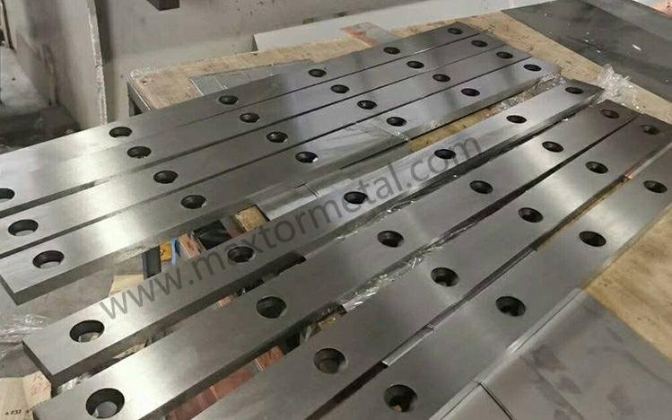
By Nancy Wu, Senior Manufacturing Engineer (Production Engineering), Maxtor Metal — SME–CMfgE, PMP, Six Sigma Black Belt, ASM International certifications
Scope note: هذا الدليل هو مرجع تقني لدعم أعمال الإعداد المقاسة. اتبع دائماً دليل خدمة الشركة المصنعة (OEM) وإجراءات التشغيل القياسية (SOP) الخاصة بمنشأتك للحصول على الإعدادات النهائية وإجراءات السلامة.
تؤدي عملية إعادة التجليخ (regrinding) إلى استعادة حالة الحافة، ولكنها تزيل أيضاً مادة من القطر الخارجي للسكين و/أو أوجهها. في رأس التقطيع، لا يعتبر هذا التغيير تجميلياً فحسب، بل إنه يغير ارتفاع مركز العمل ويمكن أن يبعدك بصمت عن هدف التداخل (overlap) الخاص بك. النتيجة مألوفة: تزداد النتوءات، وتتغير مورفولوجيا الحافة، وتنخفض القابلية للتكرار بين إعدادات التشغيل.
تمت كتابة هذا الدليل لفرق الإنتاج والصيانة وهندسة العمليات التي تحتاج إلى طريقة موثوقة لحساب حزم رقائق الضبط (shim stacks) بعد إعادة التجليخ. وهو يتبع عقلية "التوثيق أولاً" التي نراها في الورش المنضبطة (بما في ذلك سير عمل Maxtor Metal الموجه نحو مراقبة الجودة)، لأن الهدف ليس إعداداً يعتمد على "الشعور"، بل إعداداً مقاساً وقابلاً للتكرار.
In this context, the practical objective is simple: restore slitting knife center height so your overlap target stays where you set it.
- Purpose: compute shim stacks to restore center height post‑regrind
- Audience: production, maintenance, and process engineering teams
- Outcomes: accurate regrinding thickness reduction compensation, overlap restored, defects reduced
ملاحظة هندسية: إن تعويض تقليل السماكة الناتج عن إعادة التجليخ هو عملية حساب وإضافة رقائق ضبط (shim) إلى حزمة السكاكين لاستعادة ارتفاع المركز الأصلي والتداخل (overlap) بعد فقدان القطر الخارجي (OD) أو السماكة الناتج عن إعادة التجليخ. بدون هذا التعويض، ستنتج نفس تهيئة الفواصل المستخدمة قبل إعادة التجليخ تداخلاً أقل، مما يزيد من تكوّن النتوءات ويقلل من ثبات القطع. [→ انظر صفحة Maxtor Metal Shear Blades للتعرف على مبادئ إدارة خلوص القطع]
أساسيات هندسة التقطيع
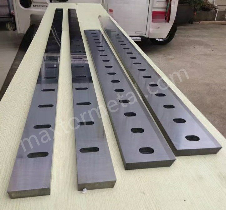
In Maxtor Metal’s shear blade manufacturing workflow, post-regrind overlap verification is treated as a mandatory checkpoint before blades are returned to service.
أهداف التخليص والتداخل
Clearance and overlap are the two geometry knobs that most directly control edge quality. In practical terms:
- Clearance is the lateral gap between mating knives (or knife and anvil), typically managed by spacers and alignment.
- تداخل is the depth the knives “bite” past the theoretical tangent line, typically set by center distance (or equivalent adjustment).
When overlap drifts low after a regrind, you tend to see more tearing and a larger burr because the cut transitions toward bending/fracture rather than stable shearing. Burr formation is a broad topic across cutting processes, but the central mechanism is consistent: edge deformation at exit and loss of controlled shear are primary drivers (see the CIRP Annals review on burr analysis and control).
Cant angle and speed differential
Cant angle and speed differential affect how the work is presented to the edge and how the cut “tracks” across the width. They don’t replace correct overlap and clearance—they fine-tune stability.
- لا يمكن ضبط الزاوية can change the effective contact path length and distribute wear, but it also changes how sensitive the process is to axial runout and spacer errors.
- Speed differential (when used) influences slip vs. bite and can change heat and edge finish. If overlap is already marginal, speed tweaks often mask the symptom instead of fixing the cause.
Edge morphology and burr formation
Edge morphology is your fastest feedback loop.
- Uniform roll-over burr often suggests insufficient effective shear (low overlap, excessive clearance, or dull edge).
- Localized heavy burr often points to runout, thickness stack error, or non-parallel faces.
- Intermittent “tooth” marks often correlate with chatter, poor arbor stiffness, or contamination trapped in the stack.
The key operational point: burr is usually the output of geometry + alignment + edge condition, not a standalone defect you “deburr away.”
طريقة تعويض إعادة التجليخ
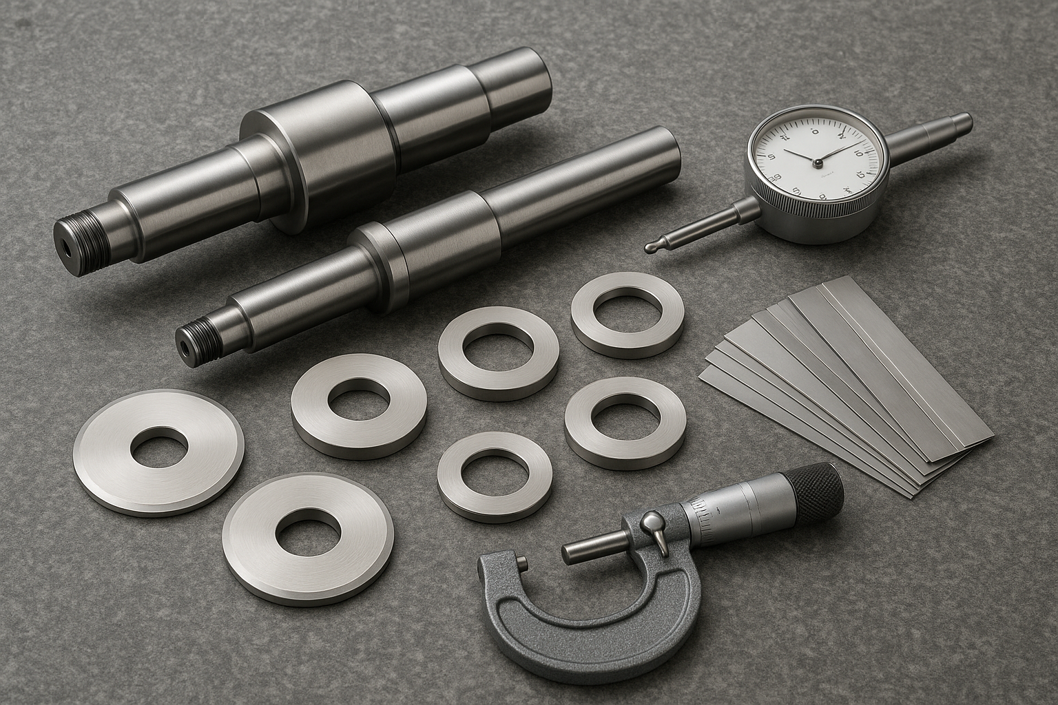
Assumptions, limits, and safety notes
Because slitting and shearing setups vary widely, treat the calculations in this guide as a first-pass, measurement-driven starting point—then verify against your machine’s documented settings.
Assumptions used in the shim math (must be true for best results):
- The machine’s locating references are stable (no meaningful wear or damage on ways/holders/keys).
- The regrind primarily changes effective edge position through radius or thickness loss (not through deformation, face dish, or geometry errors).
- Knives and spacers seat cleanly with repeatable torque and no trapped debris.
Where this method can fail or needs escalation:
- If overlap varies around rotation (runout/eccentricity), shims cannot “average out” the issue—address runout, face condition, or arbor/bearing problems first.
- If the holder/ways are worn, adding shims may temporarily hit overlap but will not restore true alignment.
- If the process definition of “overlap” is machine-specific (common on shears vs. rotary slitters), use the OEM definition and measurement method.
Safety note (YMYL): Always follow your facility’s lockout/tagout and the OEM service manual before handling or setting knives. This guide does not replace OEM instructions or on-site safety procedures.
Center height after regrind
- Knife outside diameter (OD) → radius change changes the working center height against the mating knife.
- Knife thickness / face location (depending on how the knife is reground) → can shift where the edge sits relative to spacers and hubs.
For most slitting heads, the dominant setup change you must compensate is radius loss:
- Original radius:
R0 = OD0 / 2 - Reground radius:
R1 = OD1 / 2 - Radius reduction:
ΔR = R0 − R1
إذا arbor center distance is fixed, a reduction in radius reduces overlap by approximately the same amount on the reground member (geometry details depend on whether one or both knives are reground).
أهم النقاط الرئيسية: In many slitting setups, “same spacers as last time” after regrind is equivalent to “less overlap than last time.”
Compensation formula and shim selection flow
Use this as a shop-floor-safe method that avoids hidden assumptions.
Step 1 — Measure what changed (inputs):
Shim Calculation and Verification Log
Use a simple, repeatable record like the table below to keep shim decisions traceable across regrinds and shifts.
| مجال | قيمة |
|---|---|
| Equipment / line ID | |
| Knife / blade ID | |
| المادة / الدرجة | |
| Regrind date | |
| Measured OD0 (or last in-spec) | |
| Measured OD1 (post-regrind) | |
| Calculated ΔR or thickness loss basis | |
| Shim increment available (t_shim) | |
| Target overlap | |
| Process window | |
| Selected shim stack (list) | |
| Total shim added | |
| Verification method (overlap) | |
| Verified overlap result | |
| Runout / consistency check result | |
| First-piece cut notes (burr/edge) | |
| Final decision (accept / adjust) | |
| Technician / approver |
مراقبة المستندات: Log template v1.0. If you change your measurement method, shim inventory increments, or OEM setup definition, increment the version and note the change in your work instructions.
OD0: original knife OD (or last-known in-spec OD)OD1: post-regrind ODt_shim: available shim increments (e.g., 0.01 mm, 0.001 in)overlap_target: your process target (documented)
Step 2 — Compute radius reduction:
ΔR = (OD0 − OD1) / 2
Step 3 — Decide which side to shim (selection rule):
- If you regrind one knife in a pair, apply compensation to the reground side’s stack so the effective center height is restored.
- If you regrind both knives equally, the required compensation may split across both stacks, but the net overlap change is still driven by total radius loss.
Step 4 — Convert to shim thickness: In a common “raise center height” shim approach (machine-dependent), a first-order approximation is:
Shim_add ≈ ΔR
Then select a shim stack you can actually build.
Note on evidence and verification: In shop practice, shim compensation is often treated as “matching the material removed” (a practical heuristic), but machine geometry and OEM definitions of overlap differ. Use the calculation to choose a starting point, then verify overlap and cut quality, and defer to the OEM manual and your facility SOP for final settings. (For a practice-oriented discussion of shimming, consult your OEM service documentation. )
Rounding using a process window (recommended):
- Define your acceptable overlap band:
overlap_window = [overlap_low, overlap_high]. - If multiple shim stacks are possible, many maintenance teams prefer a result in the upper half of the window (to reduce the risk of underlap as parts settle or lightly wear), while still staying within OEM limits.
- If you cannot land inside the window due to shim increments, choose the closest safe value and re-measure overlap and cut quality, then iterate.
Example (metric-first): if t_shim = 0.05 mm (~0.002 in) and your overlap window is `1.45–1.55 mm` (~0.057–0.061 in), values like 1.48–1.52 mm are commonly preferred over values near the lower bound, assuming OEM guidance allows it.
Rule of thumb: use math to pick a starting stack, but use overlap verification to “close the loop.”
Step 5 — Build the stack deliberately:
- Prefer fewer shims (less interface error) if you can hit the value.
- Keep shims clean and flat; one trapped burr can defeat the whole calculation.
Tolerance stack and verification points
Two realities make shim math fail in the field:
- Thickness stack-up error (spacers + shims + knife faces)
- Runout / face parallelism that changes effective overlap around the rotation
Verification points to keep it honest:
- Axial runout check after assembly (dial indicator on a clean reference surface).
- Face contact check: confirm no rocking or debris in the stack.
- Overlap confirmation at a known gauge position (use a consistent method and record it).
In practice, this is where a documented slitter knife shim stack matters: you’re not just adding thickness—you’re controlling a tolerance chain that decides whether you truly restore overlap after regrind.
When you document these checks, use recognized GD&T terms so engineering and QC are aligned (see ASME Y14.5 dimensioning and tolerancing guidance و ISO 1101 geometrical tolerancing standard).
Clearance Re-check After Regrind
إعادة التجليخ التي تزيل سمكاً من وجوه السكاكين ستغير أيضاً الخلوص الجانبي في حزمة التجميع. بعد التعويض بشرائح الضبط، قم بإعادة التحقق من الخلوص باستخدام الطريقة القياسية للعملية لديك (مقياس السمك "الفيلر" أو المرجع الخاص بالمُصنّع الأصلي). النطاق المستهدف: عادةً 5%–10% من سمك الخامة لسكاكين القص. لمعرفة تسلسل الإعداد الكامل — خط الأساس لمقياس الفيلر عند ثلاث نقاط، وفحص التوازي بمؤشر القياس الدائري، وجدول تشخيص العيوب الذي يربط نوع الرايش بالسبب الجذر — انظر خلوص سكاكين القص: قاعدة الـ 5–10 بالمائة ودليل إجراءات التشغيل القياسية (SOP) للإعداد.
Once clearance is confirmed, the next operational question is whether to continue running on the current edge or rotate to a fresh one first. Defining that decision in advance—with burr-threshold bands by material class and a fixed rotation sequence—prevents reactive choices at the machine. A structured framework for this is documented in the 4-Edge Reversible Blade Rotation Schedule and Regrind Criteria SOP.
If chipping recurs after clearance correction and rotation, the fracture surface itself carries the diagnostic evidence: fatigue beach marks redirect attention to residual setup or grinding variables, while coarse cleavage points to hardness or impact overload. The Shear Blade Edge Chipping Root Cause Analysis and Fractography guide provides the shop-floor inspection workflow and corrective decision tree.
مثال عملي (مقص هيدروليكي ذو ذراع متأرجح)

The example below is machine-specific (a hydraulic swing beam shear), but it illustrates the same disciplined loop used in rotary slitting: measure → calculate → choose a buildable shim stack → verify overlap → iterate.
ملحوظة: For a swing beam shear, OD0/OD1 in this example represent blade thickness; the equivalent center-height displacement relationship depends on the machine’s OEM definition. For rotary slitters, OD refers to the knife outside diameter—the formulas look the same, but the underlying geometry is different.
Equipment & assumptions
Regrind limit: discard blade when total cumulative thickness loss exceeds 1.5 mm (OEM-specific; confirm with your machine documentation).
- Equipment type: Hydraulic Swing Beam Shear
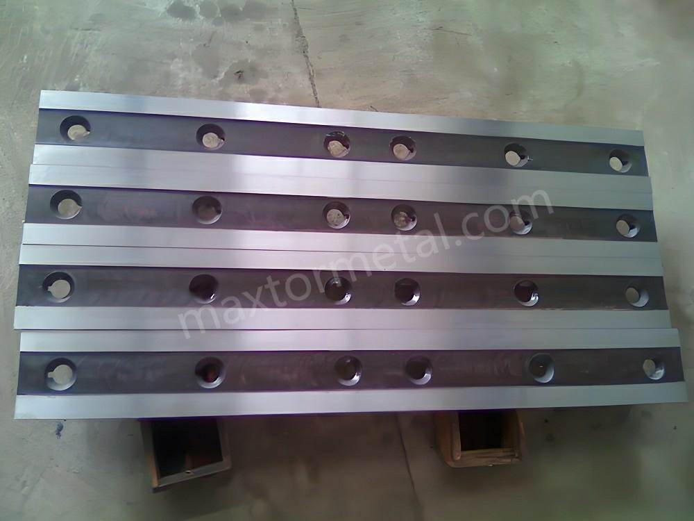
- Blade material: D2 (heat-treated), top and bottom blades. Maxtor Metal supplies D2 shear blades with documented pre- and post-grind OD records, supporting this type of traceability. When deciding between D2 and SKD11 for a specific shearing application, the choice hinges on carbide microstructure and dominant failure mode — see the D2 vs SKD11 tool steel selection guide for shearing blades for the full framework. For operations cutting AHSS or UHSS where D2 wear rate becomes a throughput constraint, a tungsten carbide inlaid construction can extend regrind intervals — see the Tungsten Carbide Inlaid Shear Blades ROI Guide for AHSS for the cost-per-meter comparison framework
- Blade length: 3,200 mm
- Assumption: machine locating references are stable; only shim compensation is needed (no guide/ram re-alignment)
Inputs (measured)
OD0(pre-grind thickness): 30.00 mmOD1(post-grind thickness): 29.64 mm- Thickness removed: 0.36 mm
- Shim increment available (
t_shim): 0.05 mm - Overlap target: 1.50 mm
- Process window: 1.45–1.55 mm
Measurement sequence (to reduce bad inputs)
- Use a calibrated 0–50 mm digital micrometer (0.001 mm resolution).
- Measure thickness at 5 positions (left end, 1/4, center, 3/4, right end).
- Use the average thickness for calculation.
First-pass compensation
- Theoretical compensation (thickness loss): 0.36 mm
Attempt #1 (close to theory, but outside window):
- Shim stack: 0.20 + 0.10 + 0.05 = 0.35 mm
- Verified overlap: ≈ 1.43 mm (below the 1.45 mm lower limit)
- Observations after ~20 test cuts on 3 mm low-carbon steel: intermittent mid-span burr increase and slightly worse consistency.
Attempt #2 (within window):
- حزمة شرائح الضبط: 0.20 + 0.10 + 0.10 = 40 مم
- Verified overlap: 48 مم (داخل النطاق المسموح)
- فحص مؤشر القياس الدائري: أقصى تفاوت بطول السكينة ≈ 0.03 مم
النتائج (ملاحظات الإنتاج)
تم رصدها على حوالي 500 لوح من ASTM A36 بسمك 3 مم:
تم تسجيل الملاحظات التالية أثناء تجربة صيانة أُجريت في مركز خدمة الصلب باستخدام سكاكين قص من طراز Maxtor Metal D2 (بطول 3,200 مم، معالجة حرارياً بالتفريغ). تم إخفاء هوية العميل وفقاً لممارسات الإفصاح القياسية.
| متري | حزمة 0.35 مم | حزمة 0.40 مم |
|---|---|---|
| التداخل المحقق | ≈1.43 مم | 48 مم |
| سلوك الرايش | أعلى قليلاً + غير منتظم | منتظم، ضمن الحدود المقبولة في الورشة |
| نسبة الإنتاج المقبول من المرة الأولى (First-pass yield) | ~96% | ~99% |
| زمن التوقف للتعديل الدقيق للجودة | مرة واحدة/وردية | لا يوجد |
الخلاصة: كون القيمة “قريبة” من القيمة المحسوبة ليس كافياً عندما تكون تدرجات شرائح الضبط سميكة. إن تحديد نطاق مسموح به مع التحقق هو ما يحقق نتائج قابلة للتكرار.
سكاكين لا مركزية/غير دائرية
تعريف مركز العمل المتوسط
ليست كل سكينة دائرية تماماً أثناء الخدمة — خاصة بعد التلف أو التركيب الخاطئ أو التآكل غير المتساوي. لأعمال التعويض، قم بتحديد مركز العمل المتوسط:
- موضع المركز الذي يمثل السكينة بأفضل شكل أثناء القطع، محسوباً كمتوسط عبر الدوران، تحت ظروف التثبيت.
يكتسب هذا التعريف أهميته لأن شرائح الضبط تصحح ارتفاع الحزمة الإستاتيكي, ، وليس اللامركزية الديناميكية.
التحقق متعدد الزوايا وطريقة الوتر/الخيط
إذا كنت تشتبه في وجود لامركزية (سبب شائع لظاهرة “قياساتها سليمة، لكن قطعها مختلف”)، فعاملها كـ تعويض سكاكين التتقطيع الطولي ذات اللامركزية مسألة أولاً، وليس مسألة شرائح ضبط:
- افحص القطر الخارجي/موضع الحد عند مواضع زاوية متعددة (على سبيل المثال: 0°، 90°، 180°، 270°).
- استخدم طريقة الوتر/الخيط أو طريقة مسح المؤشر لتحديد النقاط المرتفعة/المنخفضة.
إذا كانت السكينة تعاني من بروزات محيطية ملموسة، فإن حزمة شرائح الضبط “الصحيحة” ستبدو خاطئة عند بعض الزوايا — وهذه حقيقة قياس وليست خطأ من الفني.
ما يمكن لشرائح الضبط تصحيحه وما لا يمكنها تصحيحه
شرائح الضبط أداة فعالة، لكنها محدودة الإمكانيات.
يمكن لشرائح الضبط تصحيح:
- انحرافات ارتفاع المركز المتوسط الناتجة عن نقص نصف القطر بعد إعادة التجليخ
- التغيرات المحورية الصغيرة في المحاذاة الناتجة عن ضبط الحزمة المحكوم
لا يمكن لشرائح الضبط تصحيح:
- اللامركزية الكبيرة أو البروزات المحيطية في السكينة
- تموج الوجه، أو التقعر، أو رداءة التوازي
- انثناء عمود الدوران (الأربور) أو مشاكل المحامل
إذا كان التداخل يتفاوت أثناء الدوران، فعامل المشكلة كمشكلة رفرفة (Runout)/هندسة أبعاد أولاً، وليس كمشكلة اختيار شرائح ضبط.
إجراءات التشغيل القياسية (SOP) والتفاوتات
القياس والحساب
يتطلب بروتوكول توثيق إعادة التجليخ الخاص بـ Maxtor Metal OD0 و OD1 تسجيلاً لكل معرف سكينة، مما يتيح تدقيق حسابات التعويض عبر دورات تجليخ متعددة.
- Apply safe servicing controls appropriate to your facility before knife handling; in the U.S., align procedures to OSHA’s 29 CFR 1910.147 lockout/tagout standard.
- سِجِلّ
OD0وOD1using a controlled method (same tool, same technique, clean surfaces). - Compute
ΔRand the target shim addition. - Log the calculation and the selected shim stack in your shim log (date, knife ID, grinder lot, operator).
If you need a plain-language refresher on the sequence (shut down, isolate, lock/tag, verify), OSHA summarizes it in the OSHA 3120 lockout/tagout fact sheet (PDF).
Assemble and initial set
- Clean every contact surface in the stack; confirm no trapped burrs.
- Build the spacer + shim stack to the calculated value; keep shim count low.
- Tighten in a consistent pattern and torque range (per OEM procedure).
- QC note (non-promotional): Maxtor Metal records grind inputs and verifies flatness/runout with calibrated gauging, supporting repeatable regrind compensation and traceable knife history.
Inspect: runout, flatness, spacer accuracy
- Runout: indicator sweep after assembly; reject “good enough” if burr defects are the KPI.
- Flatness: verify reference faces; use ISO GPS terminology where your plant uses ISO-based drawings (see ISO 12781-1 flatness vocabulary/parameters).
- Spacer accuracy: treat spacer thickness as part of the tolerance stack; spot-check against marked values.
الخاتمة
Restoring overlap after regrind is mostly a geometry problem, not a “feel” problem. When you compute shim compensation from measured radius loss, then verify runout and stack integrity, you get stable edge morphology and fewer defect surprises.
- Key takeaways: restore center height, validate overlap, document results
- Next steps: periodic audits, update shim logs, refine targets
Teams working with Maxtor Metal shear blades can request factory OD records to use as an OD0 baseline — blade material selection and vacuum heat treatment specifications are documented in the Maxtor Metal Shear Blades engineering guide.
FAQ
كيف أحسب سماكة رقائق الضبط (shims) بعد إعادة تجليخ سكين التقطيع؟
قم بقياس القطر الخارجي (OD) قبل وبعد إعادة التجليخ، احسب ΔR = (OD0 − OD1) / 2، ثم أضف رقائق ضبط سماكتها تساوي تقريباً ΔR (مقرّبة إلى تدرجات الرقائق المتاحة لديك). تحقق من التداخل (overlap) و"الرون أوت" (runout) بعد التجميع. توفر Maxtor Metal أوراق عمل لحساب تعويض إعادة التجليخ مع شحنات السكاكين لدعم هذه العملية.
لماذا انخفض تداخلي (overlap) بعد إعادة التجليخ على الرغم من أنني استخدمت نفس الفواصل؟
لأن إعادة التجليخ تقلل من نصف قطر السكين. مع نفس حزمة الفواصل، ينخفض ارتفاع المركز الفعلي ويقل التداخل، مما قد يؤدي إلى زيادة النتوءات وتمزق الحافة.
ما الفرق بين الخلوص (clearance) والتداخل (overlap) في عملية التقطيع الطولي؟
الخلوص هو الفجوة الجانبية بين السكاكين؛ أما التداخل فهو مدى تعشيق السكاكين متجاوزة خط التماس (عمق القطع). يؤثر الخلوص على الاحتكاك وسلوك النتوءات؛ بينما يؤثر التداخل على استقرار عملية القص.
هل يمكن لرقائق الضبط (shims) إصلاح النتوءات الناتجة عن "الرون أوت" (runout)؟
بشكل غير مباشر فقط. يمكن لرقائق الضبط استعادة متوسط ارتفاع المركز، لكنها لا تستطيع التخلص من الانحراف الكبير في السكين، أو تموج الوجه، أو مشاكل عمود الدوران/المحامل التي تسبب تباين التداخل أثناء الدوران.
كيف أتحقق من أن سكين التقطيع لا مركزية (غير دائرية)؟
قم بقياس موضع الحافة أو القطر الخارجي (OD) في زوايا متعددة و/أو قم بإجراء مسح باستخدام ساعة قياس (Indicator sweep). إذا تغيرت القراءة بشكل ملحوظ مع الدوران، فسوف يختلف التداخل الخاص بك حتى مع حزمة رقائق ضبط "صحيحة".
ما الذي يجب علي فحصه بعد تجميع حزمة رقائق الضبط (shim stack)؟
Prüfen Sie den axialen Rundlauf (Runout), die Ebenheit der Referenzfläche und die Genauigkeit der Distanzring-Dicke. Verwenden Sie konsistente Methoden und dokumentieren Sie die Ergebnisse, damit die nächste Einrichtung auf Basis validierter Daten beginnt.
ما هي قاعدة OSHA التي تنطبق على تغيير سكاكين التقطيع في الولايات المتحدة؟
استخدم إجراءات تتماشى مع قاعدة OSHA للتحكم في الطاقة الخطرة، 29 CFR 1910.147، والتي تتطلب الإغلاق، والعزل، و"القفل/الوسم" (Lockout/Tagout)، والتحقق قبل البدء بالصيانة.
حول المؤلف
نانسي وو هو Senior Manufacturing Engineer في Production Engineering (PE) في Maxtor Metal، مع 12 سنة of experience supporting industrial blade manufacturing and maintenance workflows. Her work focuses on process engineering for precision-ground blades, including material and coating selection (D2, M2, H13, powder metallurgy steels, and carbide) and high-precision CNC grinding programming.
أوراق اعتماد: SME – CMfgE, مدير مشاريع معتمد (PMP), Six Sigma Black Belt، و ASM International certifications.
Transparency note: This article is intended as a technical reference and does not replace OEM manuals, on-site safety procedures, or professional engineering judgment. Always verify overlap/clearance with the method defined by your equipment manufacturer and your facility SOP.

 English
 Spanish
 Italian
 French
 Portuguese
 Russian
 German
 Arabic
 Hindi
 Vietnamese
 Indonesian
 Japanese
 Korean