By Nancy Wu, Senior Manufacturing Engineer (Production Engineering), Maxtor Metal — SME–CMfgE, PMP, Six Sigma Black Belt, ASM International certifications
Scope note: Panduan ini merupakan referensi teknis untuk mendukung pekerjaan pengaturan terukur. Selalu ikuti manual servis OEM dan SOP fasilitas Anda untuk pengaturan akhir dan prosedur keselamatan.
Gerinda ulang memulihkan kondisi tepi, tetapi juga menghilangkan material dari diameter luar (OD) dan/atau permukaan pisau. Pada kepala slitting, perubahan itu tidak hanya bersifat kosmetik—itu menggeser ketinggian pusat kerja dan dapat secara diam-diam menjauhkan Anda dari target overlap Anda. Hasilnya sudah umum: gerinda bertambah, morfologi tepi berubah, dan pengulangan antar-setup menurun.
Panduan ini ditulis untuk tim produksi, pemeliharaan, dan teknik proses yang membutuhkan cara andal untuk menghitung tumpukan shim setelah gerinda ulang. Panduan ini mengikuti pola pikir "dokumentasi yang utama" yang kita lihat di bengkel-bengkel yang disiplin (termasuk alur kerja Maxtor Metal yang berorientasi pada kontrol kualitas), karena tujuannya bukanlah pengaturan berdasarkan "perasaan", melainkan pengaturan yang terukur dan dapat diulang.
In this context, the practical objective is simple: restore slitting knife center height so your overlap target stays where you set it.
- Purpose: compute shim stacks to restore center height post‑regrind
- Audience: production, maintenance, and process engineering teams
- Outcomes: accurate regrinding thickness reduction compensation, overlap restored, defects reduced
Catatan Teknik: Kompensasi pengurangan ketebalan setelah gerinda ulang adalah proses menghitung dan menambahkan material shim ke tumpukan pisau untuk memulihkan ketinggian pusat dan overlap asli setelah hilangnya diameter luar (OD) atau ketebalan akibat gerinda ulang. Tanpa kompensasi ini, konfigurasi spacer yang sama yang digunakan sebelum gerinda ulang akan menghasilkan overlap yang lebih rendah, meningkatkan pembentukan gerinda (burr) dan mengurangi konsistensi potongan. [→ Lihat halaman Maxtor Metal Shear Blades untuk prinsip pengelolaan celah (gap)]
Dasar-dasar geometri slitting
In Maxtor Metal’s shear blade manufacturing workflow, post-regrind overlap verification is treated as a mandatory checkpoint before blades are returned to service.
Clearance and overlap targets
Clearance and overlap are the two geometry knobs that most directly control edge quality. In practical terms:
- Izin is the lateral gap between mating knives (or knife and anvil), typically managed by spacers and alignment.
- Overlap is the depth the knives “bite” past the theoretical tangent line, typically set by center distance (or equivalent adjustment).
When overlap drifts low after a regrind, you tend to see more tearing and a larger burr because the cut transitions toward bending/fracture rather than stable shearing. Burr formation is a broad topic across cutting processes, but the central mechanism is consistent: edge deformation at exit and loss of controlled shear are primary drivers (see the CIRP Annals review on burr analysis and control).
Cant angle and speed differential
Cant angle and speed differential affect how the work is presented to the edge and how the cut “tracks” across the width. They don’t replace correct overlap and clearance—they fine-tune stability.
- Cant angle can change the effective contact path length and distribute wear, but it also changes how sensitive the process is to axial runout and spacer errors.
- Speed differential (when used) influences slip vs. bite and can change heat and edge finish. If overlap is already marginal, speed tweaks often mask the symptom instead of fixing the cause.
Edge morphology and burr formation
Edge morphology is your fastest feedback loop.
- Uniform roll-over burr often suggests insufficient effective shear (low overlap, excessive clearance, or dull edge).
- Localized heavy burr often points to runout, thickness stack error, or non-parallel faces.
- Intermittent “tooth” marks often correlate with chatter, poor arbor stiffness, or contamination trapped in the stack.
The key operational point: burr is usually the output of geometry + alignment + edge condition, not a standalone defect you “deburr away.”
Metode kompensasi gerinda ulang
Assumptions, limits, and safety notes
Because slitting and shearing setups vary widely, treat the calculations in this guide as a first-pass, measurement-driven starting point—then verify against your machine’s documented settings.
Assumptions used in the shim math (must be true for best results):
- The machine’s locating references are stable (no meaningful wear or damage on ways/holders/keys).
- The regrind primarily changes effective edge position through radius or thickness loss (not through deformation, face dish, or geometry errors).
- Knives and spacers seat cleanly with repeatable torque and no trapped debris.
Where this method can fail or needs escalation:
- If overlap varies around rotation (runout/eccentricity), shims cannot “average out” the issue—address runout, face condition, or arbor/bearing problems first.
- If the holder/ways are worn, adding shims may temporarily hit overlap but will not restore true alignment.
- If the process definition of “overlap” is machine-specific (common on shears vs. rotary slitters), use the OEM definition and measurement method.
Safety note (YMYL): Always follow your facility’s lockout/tagout and the OEM service manual before handling or setting knives. This guide does not replace OEM instructions or on-site safety procedures.
Center height after regrind
- Knife outside diameter (OD) → radius change changes the working center height against the mating knife.
- Knife thickness / face location (depending on how the knife is reground) → can shift where the edge sits relative to spacers and hubs.
For most slitting heads, the dominant setup change you must compensate is radius loss:
- Original radius:
R0 = OD0 / 2 - Reground radius:
R1 = OD1 / 2 - Radius reduction:
ΔR = R0 − R1
Jika arbor center distance is fixed, a reduction in radius reduces overlap by approximately the same amount on the reground member (geometry details depend on whether one or both knives are reground).
Poin Penting: In many slitting setups, “same spacers as last time” after regrind is equivalent to “less overlap than last time.”
Compensation formula and shim selection flow
Use this as a shop-floor-safe method that avoids hidden assumptions.
Step 1 — Measure what changed (inputs):
Shim Calculation and Verification Log
Use a simple, repeatable record like the table below to keep shim decisions traceable across regrinds and shifts.
| Field | Nilai |
|---|---|
| Equipment / line ID | |
| Knife / blade ID | |
| Material / grade | |
| Regrind date | |
| Measured OD0 (or last in-spec) | |
| Measured OD1 (post-regrind) | |
| Calculated ΔR or thickness loss basis | |
| Shim increment available (t_shim) | |
| Target overlap | |
| Process window | |
| Selected shim stack (list) | |
| Total shim added | |
| Verification method (overlap) | |
| Verified overlap result | |
| Runout / consistency check result | |
| First-piece cut notes (burr/edge) | |
| Final decision (accept / adjust) | |
| Technician / approver |
Document control: Log template v1.0. If you change your measurement method, shim inventory increments, or OEM setup definition, increment the version and note the change in your work instructions.
OD0: original knife OD (or last-known in-spec OD)OD1: post-regrind ODt_shim: available shim increments (e.g., 0.01 mm, 0.001 in)overlap_target: your process target (documented)
Step 2 — Compute radius reduction:
ΔR = (OD0 − OD1) / 2
Step 3 — Decide which side to shim (selection rule):
- If you regrind one knife in a pair, apply compensation to the reground side’s stack so the effective center height is restored.
- If you regrind both knives equally, the required compensation may split across both stacks, but the net overlap change is still driven by total radius loss.
Step 4 — Convert to shim thickness: In a common “raise center height” shim approach (machine-dependent), a first-order approximation is:
Shim_add ≈ ΔR
Then select a shim stack you can actually build.
Note on evidence and verification: In shop practice, shim compensation is often treated as “matching the material removed” (a practical heuristic), but machine geometry and OEM definitions of overlap differ. Use the calculation to choose a starting point, then verify overlap and cut quality, and defer to the OEM manual and your facility SOP for final settings. (For a practice-oriented discussion of shimming, consult your OEM service documentation. )
Rounding using a process window (recommended):
- Define your acceptable overlap band:
overlap_window = [overlap_low, overlap_high]. - If multiple shim stacks are possible, many maintenance teams prefer a result in the upper half of the window (to reduce the risk of underlap as parts settle or lightly wear), while still staying within OEM limits.
- If you cannot land inside the window due to shim increments, choose the closest safe value and re-measure overlap and cut quality, then iterate.
Example (metric-first): if t_shim = 0.05 mm (~0.002 in) and your overlap window is `1.45–1.55 mm` (~0.057–0.061 in), values like 1.48–1.52 mm are commonly preferred over values near the lower bound, assuming OEM guidance allows it.
Rule of thumb: use math to pick a starting stack, but use overlap verification to “close the loop.”
Step 5 — Build the stack deliberately:
- Prefer fewer shims (less interface error) if you can hit the value.
- Keep shims clean and flat; one trapped burr can defeat the whole calculation.
Tolerance stack and verification points
Two realities make shim math fail in the field:
- Thickness stack-up error (spacers + shims + knife faces)
- Runout / face parallelism that changes effective overlap around the rotation
Verification points to keep it honest:
- Axial runout check after assembly (dial indicator on a clean reference surface).
- Face contact check: confirm no rocking or debris in the stack.
- Overlap confirmation at a known gauge position (use a consistent method and record it).
In practice, this is where a documented slitter knife shim stack matters: you’re not just adding thickness—you’re controlling a tolerance chain that decides whether you truly restore overlap after regrind.
When you document these checks, use recognized GD&T terms so engineering and QC are aligned (see ASME Y14.5 dimensioning and tolerancing guidance dan ISO 1101 geometrical tolerancing standard).
Clearance Re-check After Regrind
Regrinding that removes thickness from knife faces will also alter the lateral clearance in the stack. After shim compensation, re-verify clearance using your process-standard method (feeler gauge or OEM reference). Target range: typically 5%–10% of material thickness for shear blades.
Contoh pengerjaan (Mesin potong hidrolik swing beam)

The example below is machine-specific (a hydraulic swing beam shear), but it illustrates the same disciplined loop used in rotary slitting: measure → calculate → choose a buildable shim stack → verify overlap → iterate.
Catatan: For a swing beam shear, OD0/OD1 in this example represent blade thickness; the equivalent center-height displacement relationship depends on the machine’s OEM definition. For rotary slitters, OD refers to the knife outside diameter—the formulas look the same, but the underlying geometry is different.
Equipment & assumptions
Regrind limit: discard blade when total cumulative thickness loss exceeds 1.5 mm (OEM-specific; confirm with your machine documentation).
- Equipment type: Hydraulic Swing Beam Shear
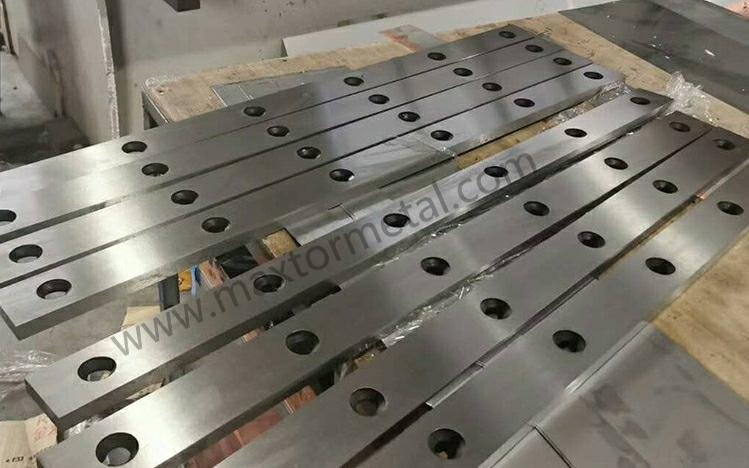
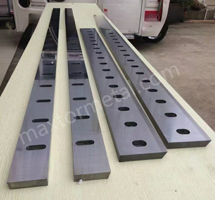
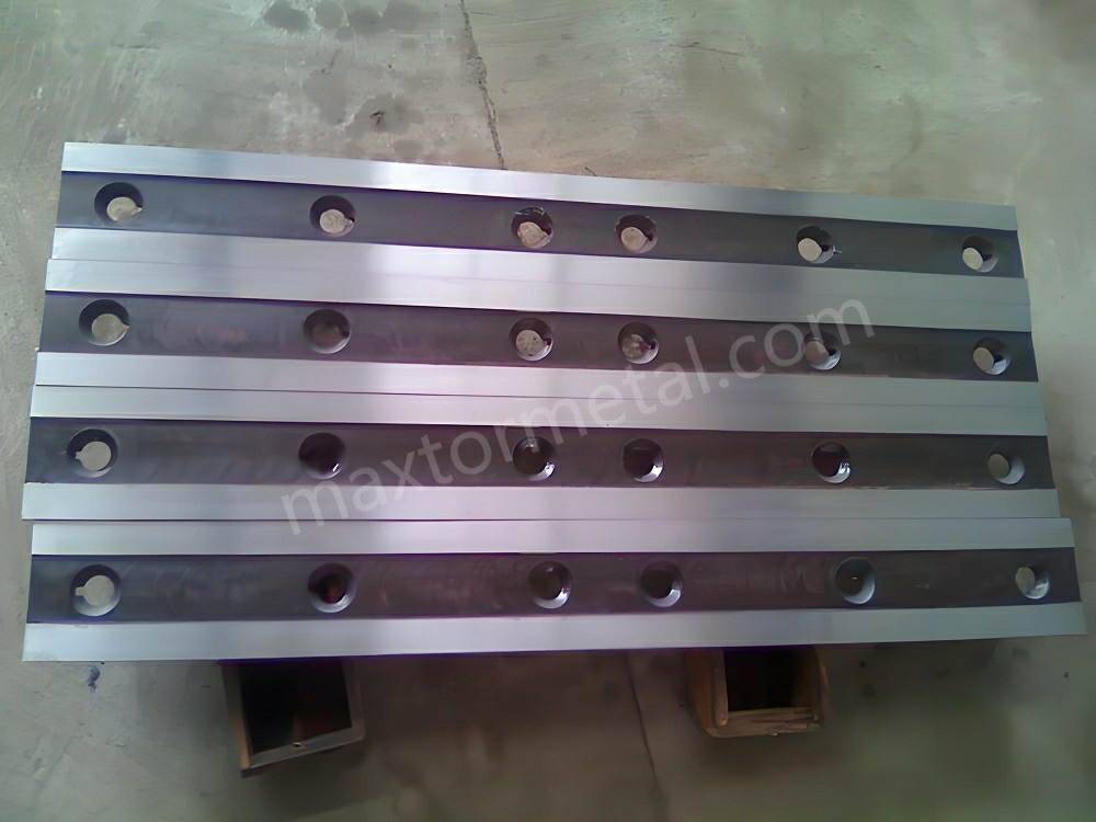
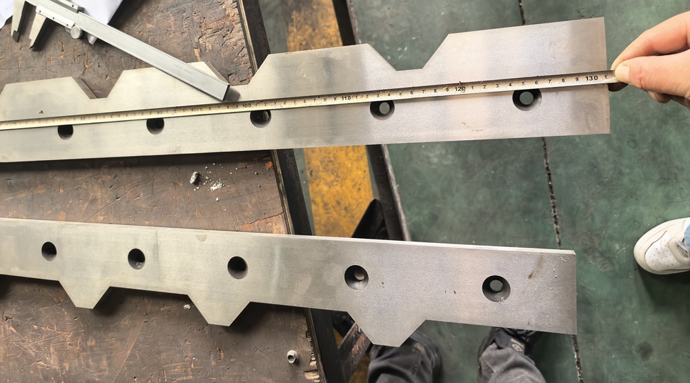
- Blade material: D2 (heat-treated), top and bottom blades. Maxtor Metal supplies D2 shear blades with documented pre- and post-grind OD records, supporting this type of traceability.
- Blade length: 3,200 mm
- Assumption: machine locating references are stable; only shim compensation is needed (no guide/ram re-alignment)
Inputs (measured)
OD0(pre-grind thickness): 30.00 mmOD1(post-grind thickness): 29.64 mm- Thickness removed: 0.36 mm
- Shim increment available (
t_shim): 0.05 mm - Overlap target: 1.50 mm
- Process window: 1.45–1.55 mm
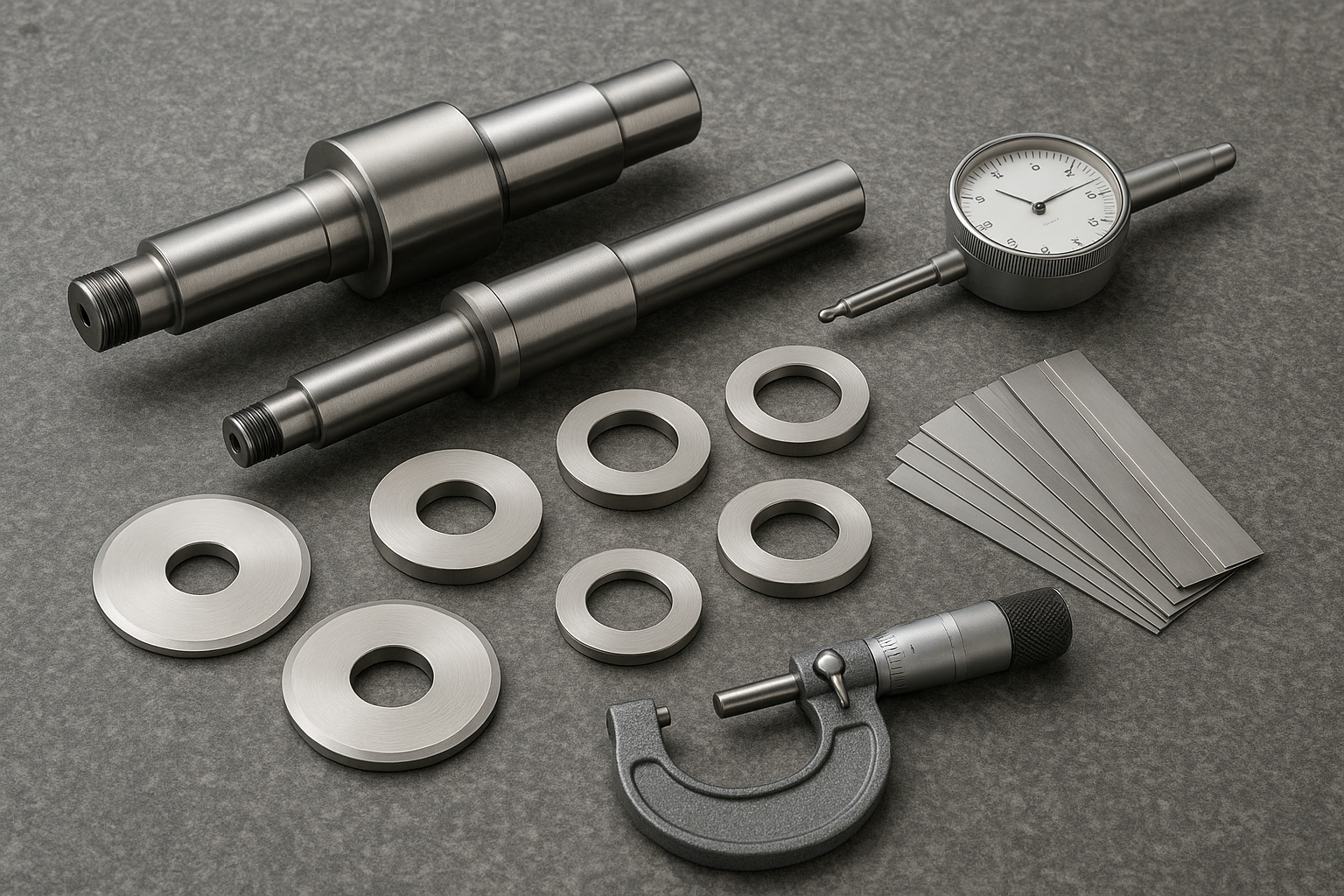
Measurement sequence (to reduce bad inputs)
- Use a calibrated 0–50 mm digital micrometer (0.001 mm resolution).
- Measure thickness at 5 positions (left end, 1/4, center, 3/4, right end).
- Use the average thickness for calculation.
First-pass compensation
- Theoretical compensation (thickness loss): 0.36 mm
Attempt #1 (close to theory, but outside window):
- Shim stack: 0.20 + 0.10 + 0.05 = 0.35 mm
- Verified overlap: ≈ 1.43 mm (below the 1.45 mm lower limit)
- Observations after ~20 test cuts on 3 mm low-carbon steel: intermittent mid-span burr increase and slightly worse consistency.
Attempt #2 (within window):
- Shim stack: 0.20 + 0.10 + 0.10 = 0.40 mm
- Verified overlap: 1.48 mm (inside window)
- Dial-indicator check: max variation along blade length ≈ 0,03 mm
Results (production observation)
Observed on ~500 sheets of 3 mm ASTM A36:
The following observations were recorded during a maintenance trial conducted at a steel service center using Maxtor Metal D2 shear blades (3,200 mm, vacuum heat-treated). Customer identity anonymized per standard disclosure practice.
| Metrik | 0.35 mm stack | 0.40 mm stack |
|---|---|---|
| Verified overlap | ≈1.43 mm | 1.48 mm |
| Burr behavior | slightly higher + uneven | uniform, within shop acceptance |
| First-pass yield | ~96% | ~99% |
| Downtime for quality micro-adjust | 1 time/shift | none |
Takeaway: being “close” to the calculated value is not enough when shim increments are coarse. A defined window plus verification produces the repeatable result.
Pisau eksentrik/non-sirkular
Mean working center definition
Not every knife is perfectly circular in service—especially after damage, poor mounting, or uneven wear. For compensation work, define a mean working center:
- The center position that best represents the knife during cutting, averaged over rotation, under clamped conditions.
This definition matters because shims correct static stack height, not dynamic eccentricity.
Multi‑angle verification and chord/stringline
If you suspect eccentricity (a common cause of “it measures fine, but it cuts differently”), treat it as an eccentric slitter knife compensation question first, not a shim question:
- Check OD/edge position at multiple angular positions (e.g., 0°, 90°, 180°, 270°).
- Use a chord/stringline or indicator sweep method to identify high/low spots.
If the knife has meaningful lobing, your “correct” shim stack will look wrong at some angles—and that’s a measurement truth, not an installer mistake.
What shims can and cannot correct
Shims are powerful, but limited.
Shims can correct:
- Mean center height offsets from regrind radius loss
- Small axial alignment changes caused by controlled stack adjustments
Shims cannot correct:
- Significant knife eccentricity or lobing
- Face waviness, dish, or poor parallelism
- Arbor bend or bearing issues
If overlap varies around rotation, treat it as a runout/geometry problem first, not a shim-selection problem.
SOP dan toleransi
Measure and compute
Maxtor Metal’s regrind documentation protocol requires OD0 dan OD1 to be logged per blade ID, enabling compensation calculations to be audited across multiple grind cycles.
- Apply safe servicing controls appropriate to your facility before knife handling; in the U.S., align procedures to OSHA’s 29 CFR 1910.147 lockout/tagout standard.
- Catatan
OD0danOD1using a controlled method (same tool, same technique, clean surfaces). - Compute
ΔRand the target shim addition. - Log the calculation and the selected shim stack in your shim log (date, knife ID, grinder lot, operator).
If you need a plain-language refresher on the sequence (shut down, isolate, lock/tag, verify), OSHA summarizes it in the OSHA 3120 lockout/tagout fact sheet (PDF).
Assemble and initial set
- Clean every contact surface in the stack; confirm no trapped burrs.
- Build the spacer + shim stack to the calculated value; keep shim count low.
- Tighten in a consistent pattern and torque range (per OEM procedure).
- QC note (non-promotional): Maxtor Metal records grind inputs and verifies flatness/runout with calibrated gauging, supporting repeatable regrind compensation and traceable knife history.
Inspect: runout, flatness, spacer accuracy
- Runout: indicator sweep after assembly; reject “good enough” if burr defects are the KPI.
- Flatness: verify reference faces; use ISO GPS terminology where your plant uses ISO-based drawings (see ISO 12781-1 flatness vocabulary/parameters).
- Spacer accuracy: treat spacer thickness as part of the tolerance stack; spot-check against marked values.
Kesimpulan
Restoring overlap after regrind is mostly a geometry problem, not a “feel” problem. When you compute shim compensation from measured radius loss, then verify runout and stack integrity, you get stable edge morphology and fewer defect surprises.
- Key takeaways: restore center height, validate overlap, document results
- Next steps: periodic audits, update shim logs, refine targets
Teams working with Maxtor Metal shear blades can request factory OD records to use as an OD0 baseline — blade material selection and vacuum heat treatment specifications are documented in the Maxtor Metal Shear Blades engineering guide.
FAQ
Bagaimana cara menghitung ketebalan shim setelah gerinda ulang pisau slitter?
Ukur diameter luar (OD) sebelum dan sesudah gerinda ulang, hitung ΔR = (OD0 − OD1) / 2, lalu tambahkan shim yang kira-kira sama dengan ΔR (dibulatkan ke kenaikan shim Anda). Verifikasi overlap dan runout setelah perakitan. Maxtor Metal menyediakan lembar kerja kompensasi gerinda ulang bersama pengiriman pisau untuk mendukung proses ini.
Mengapa overlap saya turun setelah gerinda ulang meskipun saya menggunakan spacer yang sama?
Karena gerinda ulang mengurangi radius pisau. Dengan tumpukan spacer yang sama, ketinggian pusat efektif turun dan overlap berkurang, yang dapat meningkatkan gerinda (burr) dan robekan pada tepi.
Apa perbedaan antara clearance dan overlap dalam proses slitting?
Clearance adalah celah lateral antara pisau; overlap adalah seberapa jauh pisau terlibat melewati garis tangen (kedalaman gigitan). Clearance memengaruhi gesekan dan perilaku gerinda (burr); overlap memengaruhi apakah potongan tetap dalam geseran (shearing) yang stabil.
Bisakah shim memperbaiki gerinda (burr) yang disebabkan oleh runout?
Hanya secara tidak langsung. Shim dapat memulihkan ketinggian pusat rata-rata, tetapi tidak dapat menghilangkan eksentrisitas pisau yang signifikan, gelombang pada permukaan, atau masalah arbor/bantalan yang menciptakan variasi overlap selama rotasi.
Bagaimana cara memeriksa pisau slitter yang eksentrik (non-sirkular)?
Ukur posisi tepi atau diameter luar (OD) pada beberapa sudut dan/atau lakukan pemeriksaan dengan indikator. Jika bacaan berubah secara signifikan seiring rotasi, overlap Anda akan bervariasi bahkan dengan tumpukan shim yang "benar".
Apa yang harus saya periksa setelah merakit shim stack?
Periksa runout aksial, kerataan permukaan referensi, dan akurasi ketebalan spacer. Gunakan metode yang konsisten dan dokumentasikan hasilnya agar pengaturan berikutnya dimulai dari data yang sudah terverifikasi baik.
Aturan OSHA apa yang berlaku untuk penggantian pisau slitter di AS?
Gunakan prosedur yang selaras dengan aturan pengendalian energi berbahaya OSHA, 29 CFR 1910.147, yang memerlukan pemadaman, isolasi, lockout/tagout, dan verifikasi sebelum melakukan servis.
Tentang penulis
Nancy Wu is a Senior Manufacturing Engineer di dalam Production Engineering (PE) at Maxtor Metal, dengan 12 tahun of experience supporting industrial blade manufacturing and maintenance workflows. Her work focuses on process engineering for precision-ground blades, including material and coating selection (D2, M2, H13, powder metallurgy steels, and carbide) and high-precision CNC grinding programming.
Kredensial: SME – CMfgE, PMP, Six Sigma Black Belt, Dan ASM International certifications.
Transparency note: This article is intended as a technical reference and does not replace OEM manuals, on-site safety procedures, or professional engineering judgment. Always verify overlap/clearance with the method defined by your equipment manufacturer and your facility SOP.