

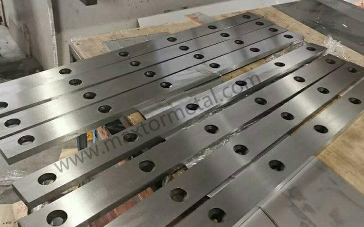
By Nancy Wu, Senior Manufacturing Engineer (Production Engineering), Maxtor Metal — SME–CMfgE, PMP, Six Sigma Black Belt, ASM International certifications
Scope note: Este guia é uma referência técnica para apoiar o trabalho de configuração medida. Siga sempre o manual de serviço do OEM e os SOPs de suas instalações para as configurações finais e procedimentos de segurança.
A retificação restaura a condição do corte, mas também remove material do diâmetro externo (OD) e/ou das faces da faca. Em um cabeçote de corte, essa mudança não é apenas estética: ela desloca a altura do centro de trabalho e pode silenciosamente desviá-lo do seu objetivo de sobreposição. O resultado é familiar: as rebarbas aumentam, a morfologia da aresta muda e a repetibilidade entre configurações cai.
Este guia foi escrito para equipes de produção, manutenção e engenharia de processos que precisam de uma forma confiável de calcular pilhas de calços após a retificação. Ele segue a mesma mentalidade de "documentação em primeiro lugar" que vemos em oficinas disciplinadas (incluindo os fluxos de trabalho orientados para o controle de qualidade da Maxtor Metal), porque o objetivo não é uma configuração baseada em "feeling", mas sim uma que seja medida e repetível.
In this context, the practical objective is simple: restore slitting knife center height so your overlap target stays where you set it.
- Purpose: compute shim stacks to restore center height post‑regrind
- Audience: production, maintenance, and process engineering teams
- Outcomes: accurate regrinding thickness reduction compensation, overlap restored, defects reduced
Nota de Engenharia: A compensação de redução de espessura após retificação é o processo de calcular e adicionar material de calço (shim) a uma pilha de facas para restaurar a altura central e a sobreposição originais após a perda de diâmetro externo (OD) ou espessura induzida pela retificação. Sem essa compensação, a mesma configuração de espaçadores usada antes da retificação produzirá uma sobreposição menor, aumentando a formação de rebarbas e reduzindo a consistência do corte. [→ Veja a página de facas de corte da Maxtor Metal para os princípios de gestão de folga]
Fundamentos da geometria de corte
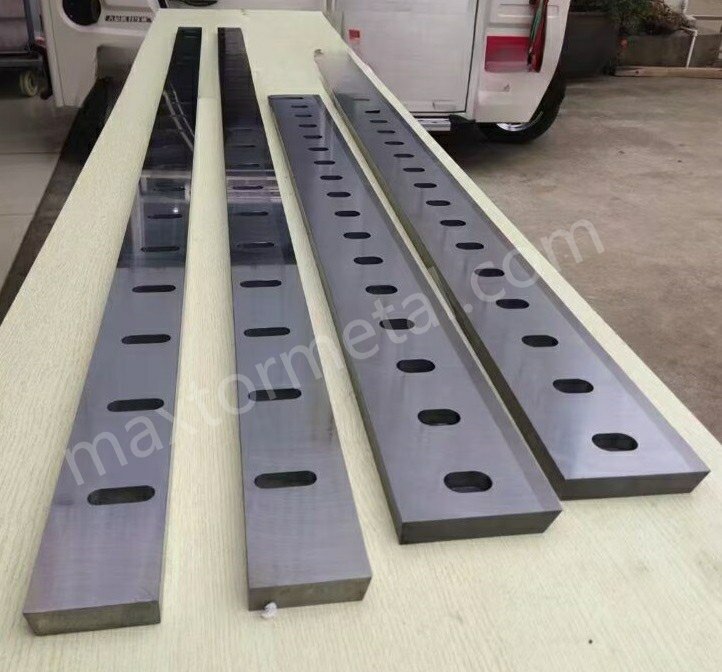
In Maxtor Metal’s shear blade manufacturing workflow, post-regrind overlap verification is treated as a mandatory checkpoint before blades are returned to service.
Clearance and overlap targets
Clearance and overlap are the two geometry knobs that most directly control edge quality. In practical terms:
- Liquidação is the lateral gap between mating knives (or knife and anvil), typically managed by spacers and alignment.
- Sobreposição is the depth the knives “bite” past the theoretical tangent line, typically set by center distance (or equivalent adjustment).
When overlap drifts low after a regrind, you tend to see more tearing and a larger burr because the cut transitions toward bending/fracture rather than stable shearing. Burr formation is a broad topic across cutting processes, but the central mechanism is consistent: edge deformation at exit and loss of controlled shear are primary drivers (see the CIRP Annals review on burr analysis and control).
Cant angle and speed differential
Cant angle and speed differential affect how the work is presented to the edge and how the cut “tracks” across the width. They don’t replace correct overlap and clearance—they fine-tune stability.
- Não consigo inclinar can change the effective contact path length and distribute wear, but it also changes how sensitive the process is to axial runout and spacer errors.
- Speed differential (when used) influences slip vs. bite and can change heat and edge finish. If overlap is already marginal, speed tweaks often mask the symptom instead of fixing the cause.
Edge morphology and burr formation
Edge morphology is your fastest feedback loop.
- Uniform roll-over burr often suggests insufficient effective shear (low overlap, excessive clearance, or dull edge).
- Localized heavy burr often points to runout, thickness stack error, or non-parallel faces.
- Intermittent “tooth” marks often correlate with chatter, poor arbor stiffness, or contamination trapped in the stack.
The key operational point: burr is usually the output of geometry + alignment + edge condition, not a standalone defect you “deburr away.”
Método de compensação por retificação
Assumptions, limits, and safety notes
Because slitting and shearing setups vary widely, treat the calculations in this guide as a first-pass, measurement-driven starting point—then verify against your machine’s documented settings.
Assumptions used in the shim math (must be true for best results):
- The machine’s locating references are stable (no meaningful wear or damage on ways/holders/keys).
- The regrind primarily changes effective edge position through radius or thickness loss (not through deformation, face dish, or geometry errors).
- Knives and spacers seat cleanly with repeatable torque and no trapped debris.
Where this method can fail or needs escalation:
- If overlap varies around rotation (runout/eccentricity), shims cannot “average out” the issue—address runout, face condition, or arbor/bearing problems first.
- If the holder/ways are worn, adding shims may temporarily hit overlap but will not restore true alignment.
- If the process definition of “overlap” is machine-specific (common on shears vs. rotary slitters), use the OEM definition and measurement method.
Safety note (YMYL): Always follow your facility’s lockout/tagout and the OEM service manual before handling or setting knives. This guide does not replace OEM instructions or on-site safety procedures.
Center height after regrind
- Knife outside diameter (OD) → radius change changes the working center height against the mating knife.
- Knife thickness / face location (depending on how the knife is reground) → can shift where the edge sits relative to spacers and hubs.
For most slitting heads, the dominant setup change you must compensate is radius loss:
- Original radius:
R0 = OD0 / 2 - Reground radius:
R1 = OD1 / 2 - Radius reduction:
ΔR = R0 − R1
Se o arbor center distance is fixed, a reduction in radius reduces overlap by approximately the same amount on the reground member (geometry details depend on whether one or both knives are reground).
Conclusão principal: In many slitting setups, “same spacers as last time” after regrind is equivalent to “less overlap than last time.”
Compensation formula and shim selection flow
Use this as a shop-floor-safe method that avoids hidden assumptions.
Step 1 — Measure what changed (inputs):
Shim Calculation and Verification Log
Use a simple, repeatable record like the table below to keep shim decisions traceable across regrinds and shifts.
| Campo | Valor |
|---|---|
| Equipment / line ID | |
| Knife / blade ID | |
| Material / grade | |
| Regrind date | |
| Measured OD0 (or last in-spec) | |
| Measured OD1 (post-regrind) | |
| Calculated ΔR or thickness loss basis | |
| Shim increment available (t_shim) | |
| Target overlap | |
| Process window | |
| Selected shim stack (list) | |
| Total shim added | |
| Verification method (overlap) | |
| Verified overlap result | |
| Runout / consistency check result | |
| First-piece cut notes (burr/edge) | |
| Final decision (accept / adjust) | |
| Technician / approver |
Document control: Log template v1.0. If you change your measurement method, shim inventory increments, or OEM setup definition, increment the version and note the change in your work instructions.
OD0: original knife OD (or last-known in-spec OD)OD1: post-regrind ODt_shim: available shim increments (e.g., 0.01 mm, 0.001 in)overlap_target: your process target (documented)
Step 2 — Compute radius reduction:
ΔR = (OD0 − OD1) / 2
Step 3 — Decide which side to shim (selection rule):
- If you regrind one knife in a pair, apply compensation to the reground side’s stack so the effective center height is restored.
- If you regrind both knives equally, the required compensation may split across both stacks, but the net overlap change is still driven by total radius loss.
Step 4 — Convert to shim thickness: In a common “raise center height” shim approach (machine-dependent), a first-order approximation is:
Shim_add ≈ ΔR
Then select a shim stack you can actually build.
Note on evidence and verification: In shop practice, shim compensation is often treated as “matching the material removed” (a practical heuristic), but machine geometry and OEM definitions of overlap differ. Use the calculation to choose a starting point, then verify overlap and cut quality, and defer to the OEM manual and your facility SOP for final settings. (For a practice-oriented discussion of shimming, consult your OEM service documentation. )
Rounding using a process window (recommended):
- Define your acceptable overlap band:
overlap_window = [overlap_low, overlap_high]. - If multiple shim stacks are possible, many maintenance teams prefer a result in the upper half of the window (to reduce the risk of underlap as parts settle or lightly wear), while still staying within OEM limits.
- If you cannot land inside the window due to shim increments, choose the closest safe value and re-measure overlap and cut quality, then iterate.
Example (metric-first): if t_shim = 0.05 mm (~0.002 in) and your overlap window is `1.45–1.55 mm` (~0.057–0.061 in), values like 1.48–1.52 mm are commonly preferred over values near the lower bound, assuming OEM guidance allows it.
Rule of thumb: use math to pick a starting stack, but use overlap verification to “close the loop.”
Step 5 — Build the stack deliberately:
- Prefer fewer shims (less interface error) if you can hit the value.
- Keep shims clean and flat; one trapped burr can defeat the whole calculation.
Tolerance stack and verification points
Two realities make shim math fail in the field:
- Thickness stack-up error (spacers + shims + knife faces)
- Runout / face parallelism that changes effective overlap around the rotation
Verification points to keep it honest:
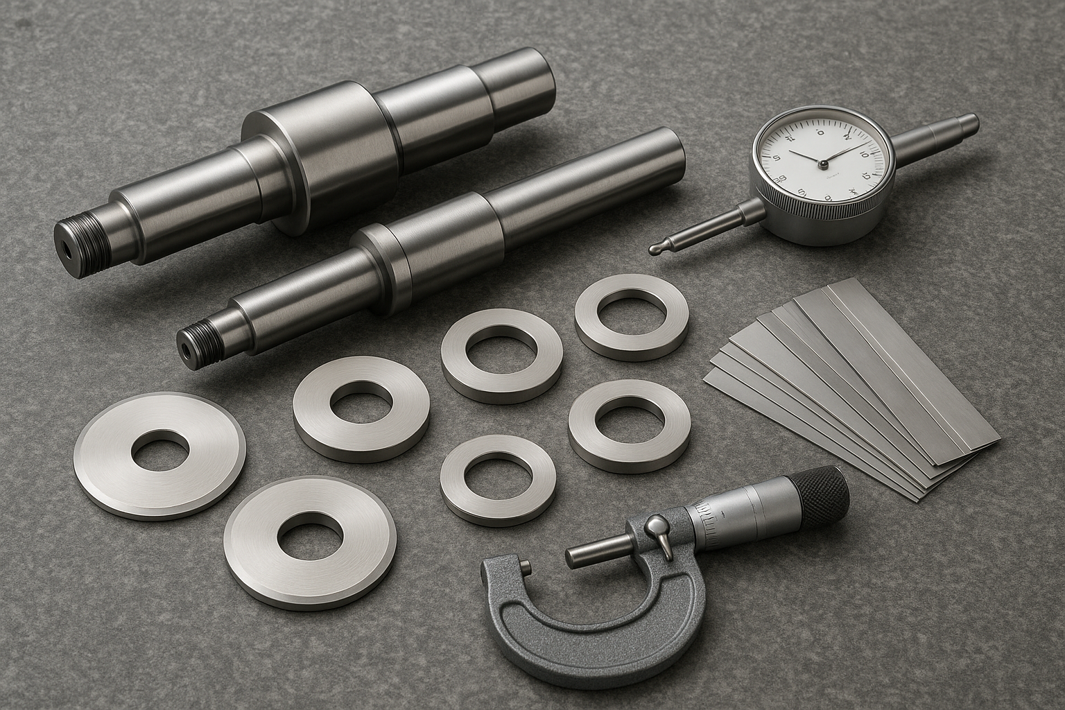
- Axial runout check after assembly (dial indicator on a clean reference surface).
- Face contact check: confirm no rocking or debris in the stack.
- Overlap confirmation at a known gauge position (use a consistent method and record it).
In practice, this is where a documented slitter knife shim stack matters: you’re not just adding thickness—you’re controlling a tolerance chain that decides whether you truly restore overlap after regrind.
When you document these checks, use recognized GD&T terms so engineering and QC are aligned (see ASME Y14.5 dimensioning and tolerancing guidance e ISO 1101 geometrical tolerancing standard).
Clearance Re-check After Regrind
A reafiação que remove espessura das faces da lâmina também altera a folga lateral no conjunto. Após a compensação com calços, reverifique a folga usando o método padrão do seu processo (calibre de folga ou referência do OEM). Faixa-alvo: tipicamente 5%–10% da espessura do material para lâminas de tesoura. Para a sequência completa de configuração — linha de base do calibre de folga em três pontos, verificação de paralelismo com relógio comparador e a tabela de diagnóstico de defeitos que mapeia o tipo de rebarba para a causa raiz — consulte o Folga para Lâminas de Tesoura: A Regra de 5–10 Por Cento e o Guia SOP de Configuração.
Once clearance is confirmed, the next operational question is whether to continue running on the current edge or rotate to a fresh one first. Defining that decision in advance—with burr-threshold bands by material class and a fixed rotation sequence—prevents reactive choices at the machine. A structured framework for this is documented in the 4-Edge Reversible Blade Rotation Schedule and Regrind Criteria SOP.
If chipping recurs after clearance correction and rotation, the fracture surface itself carries the diagnostic evidence: fatigue beach marks redirect attention to residual setup or grinding variables, while coarse cleavage points to hardness or impact overload. The Shear Blade Edge Chipping Root Cause Analysis and Fractography guide provides the shop-floor inspection workflow and corrective decision tree.
Exemplo prático (Tesoura hidráulica de viga oscilante)

The example below is machine-specific (a hydraulic swing beam shear), but it illustrates the same disciplined loop used in rotary slitting: measure → calculate → choose a buildable shim stack → verify overlap → iterate.
Observação: For a swing beam shear, OD0/OD1 in this example represent blade thickness; the equivalent center-height displacement relationship depends on the machine’s OEM definition. For rotary slitters, OD refers to the knife outside diameter—the formulas look the same, but the underlying geometry is different.
Equipment & assumptions
Regrind limit: discard blade when total cumulative thickness loss exceeds 1.5 mm (OEM-specific; confirm with your machine documentation).
- Equipment type: Hydraulic Swing Beam Shear
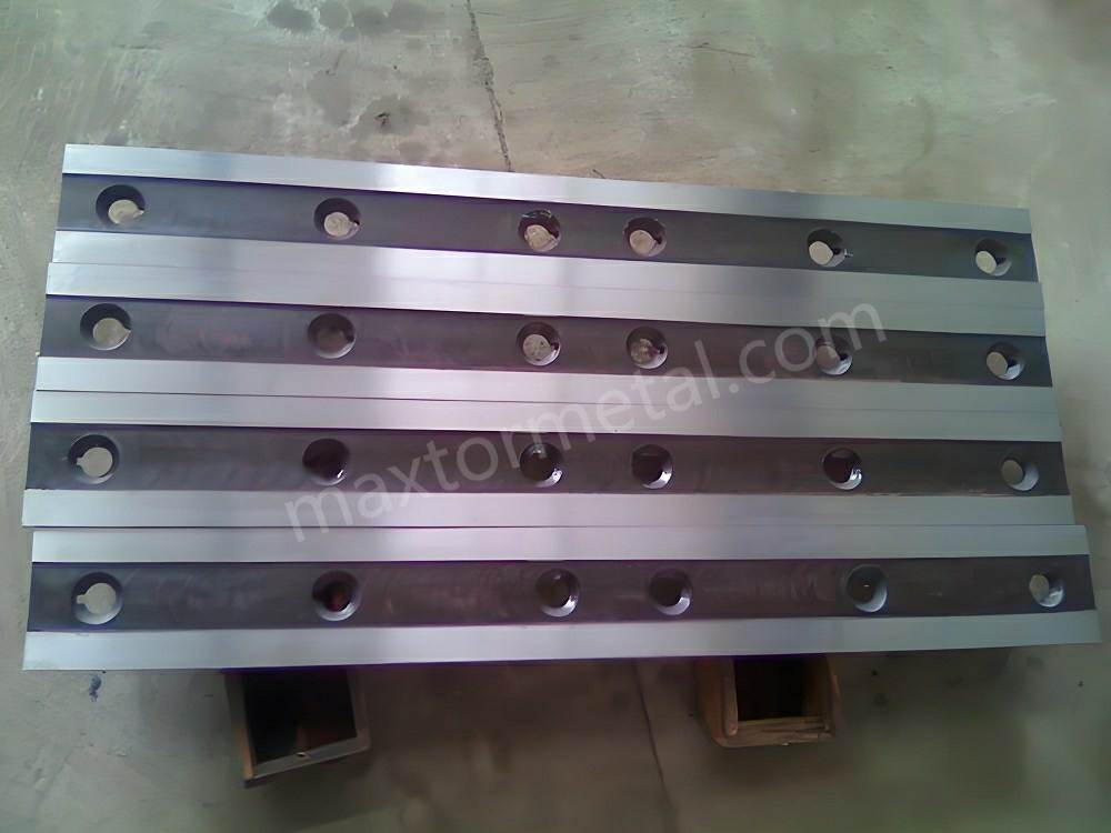
- Blade material: D2 (heat-treated), top and bottom blades. Maxtor Metal supplies D2 shear blades with documented pre- and post-grind OD records, supporting this type of traceability. When deciding between D2 and SKD11 for a specific shearing application, the choice hinges on carbide microstructure and dominant failure mode — see the D2 vs SKD11 tool steel selection guide for shearing blades for the full framework. For operations cutting AHSS or UHSS where D2 wear rate becomes a throughput constraint, a tungsten carbide inlaid construction can extend regrind intervals — see the Tungsten Carbide Inlaid Shear Blades ROI Guide for AHSS for the cost-per-meter comparison framework
- Blade length: 3,200 mm
- Assumption: machine locating references are stable; only shim compensation is needed (no guide/ram re-alignment)
Inputs (measured)
OD0(pre-grind thickness): 30.00 mmOD1(post-grind thickness): 29.64 mm- Thickness removed: 0.36 mm
- Shim increment available (
t_shim): 0.05 mm - Overlap target: 1.50 mm
- Process window: 1.45–1.55 mm
Measurement sequence (to reduce bad inputs)
- Use a calibrated 0–50 mm digital micrometer (0.001 mm resolution).
- Measure thickness at 5 positions (left end, 1/4, center, 3/4, right end).
- Use the average thickness for calculation.
First-pass compensation
- Theoretical compensation (thickness loss): 0.36 mm
Attempt #1 (close to theory, but outside window):
- Shim stack: 0.20 + 0.10 + 0.05 = 0.35 mm
- Verified overlap: ≈ 1,43 mm (abaixo do limite inferior de 1,45 mm)
- Observações após ~20 cortes de teste em aço de baixo carbono de 3 mm: aumento intermitente da rebarba no meio do vão e consistência ligeiramente pior.
Tentativa #2 (dentro da janela):
- Conjunto de calços: 0,20 + 0,10 + 0,10 = 0,40 mm
- Verified overlap: 1,48 mm (dentro da janela)
- Verificação com relógio comparador: variação máxima ao longo do comprimento da lâmina ≈ 0.03 mm
Resultados (observação de produção)
Observado em ~500 chapas de ASTM A36 de 3 mm:
As seguintes observações foram registradas durante um teste de manutenção realizado em um centro de serviço de aço usando lâminas de tesoura D2 Maxtor Metal (3.200 mm, tratadas termicamente a vácuo). A identidade do cliente foi mantida anônima de acordo com a prática padrão de divulgação.
| Métrica | Conjunto de 0,35 mm | Conjunto de 0,40 mm |
|---|---|---|
| Sobreposição verificada | ≈1,43 mm | 1,48 mm |
| Comportamento da rebarba | ligeiramente maior + irregular | uniforme, dentro da aceitação da oficina |
| Rendimento de primeira passagem (First-pass yield) | ~96% | ~99% |
| Tempo de inatividade para microajuste de qualidade | 1 vez/turno | nenhum |
Conclusão: estar “próximo” do valor calculado não é suficiente quando os incrementos dos calços são grosseiros. Uma janela definida somada à verificação produz o resultado repetível.
Facas excêntricas/não circulares
Definição de centro médio de trabalho
Nem toda lâmina é perfeitamente circular em serviço — especialmente após danos, montagem inadequada ou desgaste irregular. Para trabalhos de compensação, defina um centro médio de trabalho:
- A posição central que melhor representa a lâmina durante o corte, calculada como média ao longo da rotação, em condições de fixação.
Esta definição é importante porque os calços corrigem a altura estática do conjunto, e não a excentricidade dinâmica.
Verificação multiangular e método de corda/linha guia
Se suspeitar de excentricidade (uma causa comum para “a medição está boa, mas o corte é diferente”), trate como uma compensação de lâmina slitter excêntrica questão em primeiro lugar, e não como uma questão de calços:
- Verifique a posição do DE/gume em múltiplas posições angulares (ex.: 0°, 90°, 180°, 270°).
- Use um método de corda/linha guia ou varredura com relógio comparador para identificar pontos altos/baixos.
Se a lâmina apresentar lobulação/ovalização significativa, seu conjunto de calços “correto” parecerá errado em alguns ângulos — e isso é uma verdade da medição, não um erro do instalador.
O que os calços podem e não podem corrigir
Os calços são potentes, mas limitados.
Os calços podem corrigir:
- Desvios da altura do centro médio causados pela perda de raio na reafiação
- Pequenas alterações no alinhamento axial causadas por ajustes controlados do conjunto
Os calços não podem corrigir:
- Excentricidade ou lobulação significativa da lâmina
- Ondulação da face, conc
- Arbor bend or bearing issues
If overlap varies around rotation, treat it as a runout/geometry problem first, not a shim-selection problem.
SOP e tolerâncias
Measure and compute
Maxtor Metal’s regrind documentation protocol requires OD0 e OD1 to be logged per blade ID, enabling compensation calculations to be audited across multiple grind cycles.
- Apply safe servicing controls appropriate to your facility before knife handling; in the U.S., align procedures to OSHA’s 29 CFR 1910.147 lockout/tagout standard.
- Registro
OD0eOD1using a controlled method (same tool, same technique, clean surfaces). - Compute
ΔRand the target shim addition. - Log the calculation and the selected shim stack in your shim log (date, knife ID, grinder lot, operator).
If you need a plain-language refresher on the sequence (shut down, isolate, lock/tag, verify), OSHA summarizes it in the OSHA 3120 lockout/tagout fact sheet (PDF).
Assemble and initial set
- Clean every contact surface in the stack; confirm no trapped burrs.
- Build the spacer + shim stack to the calculated value; keep shim count low.
- Tighten in a consistent pattern and torque range (per OEM procedure).
- QC note (non-promotional): Maxtor Metal records grind inputs and verifies flatness/runout with calibrated gauging, supporting repeatable regrind compensation and traceable knife history.
Inspect: runout, flatness, spacer accuracy
- Runout: indicator sweep after assembly; reject “good enough” if burr defects are the KPI.
- Flatness: verify reference faces; use ISO GPS terminology where your plant uses ISO-based drawings (see ISO 12781-1 flatness vocabulary/parameters).
- Spacer accuracy: treat spacer thickness as part of the tolerance stack; spot-check against marked values.
Conclusão
Restoring overlap after regrind is mostly a geometry problem, not a “feel” problem. When you compute shim compensation from measured radius loss, then verify runout and stack integrity, you get stable edge morphology and fewer defect surprises.
- Key takeaways: restore center height, validate overlap, document results
- Next steps: periodic audits, update shim logs, refine targets
Teams working with Maxtor Metal shear blades can request factory OD records to use as an OD0 baseline — blade material selection and vacuum heat treatment specifications are documented in the Maxtor Metal Shear Blades engineering guide.
FAQ
Como calculo a espessura dos calços (shim) após a retificação de uma faca de corte?
Meça o diâmetro externo (OD) antes e depois da retificação, calcule ΔR = (OD0 − OD1) / 2, puis ajoutez des cales d'une épaisseur approximativement égale à ΔR (arredondado para seus incrementos de calços). Verifique a sobreposição e o batimento após a montagem. A Maxtor Metal fornece folhas de cálculo de compensação de retificação com os envios de facas para apoiar este processo.
Por que minha sobreposição (overlap) diminuiu após a retificação, mesmo usando os mesmos espaçadores?
Porque a retificação reduz o raio da faca. Com a mesma pilha de espaçadores, a altura efetiva do centro diminui e a sobreposição se reduz, o que pode aumentar a formação de rebarbas e o rasgo da borda.
Qual é a diferença entre a folga (clearance) e a sobreposição (overlap) no corte longitudinal?
A folga é o espaço lateral entre as facas; a sobreposição é o quanto as facas se engatam além da linha tangente (profundidade de mordida). A folga afeta o atrito e o comportamento das rebarbas; a sobreposição determina se o corte se mantém em um cisalhamento estável.
Os calços (shims) podem corrigir rebarbas causadas por batimento (runout)?
Apenas indiretamente. Os calços podem restaurar a altura central média, mas não podem eliminar a excentricidade significativa da faca, a ondulação da face ou problemas de eixo/rolamento que criam variação na sobreposição durante a rotação.
Como verifico se uma faca de corte é excêntrica (não circular)?
Meça a posição da aresta ou o diâmetro externo (OD) em múltiplos ângulos e/ou realize uma verificação com indicador. Se a leitura mudar significativamente com a rotação, sua sobreposição variará mesmo com uma pilha de calços "correta".
O que devo inspecionar após montar uma pilha de calços (shim stack)?
Inspecione o batimento axial (runout), a planicidade da face de referência e a precisão da espessura dos espaçadores. Use métodos consistentes e documente os resultados para que a próxima configuração comece a partir de dados de referência confiáveis.
Qual regra da OSHA se aplica à troca de facas de corte nos EUA?
Utilize procedimentos alinhados à norma da OSHA de controle de energias perigosas, 29 CFR 1910.147, que exige o desligamento, isolamento, bloqueio/etiquetagem (Lockout/Tagout) e verificação antes da manutenção.
Sobre o autor
Nancy Wu é um Engenheiro Sênior de Manufatura em Engenharia de Produção (EP) no Maxtor Metal, com 12 anos of experience supporting industrial blade manufacturing and maintenance workflows. Her work focuses on process engineering for precision-ground blades, including material and coating selection (D2, M2, H13, powder metallurgy steels, and carbide) and high-precision CNC grinding programming.
Credenciais: PME – CMfgE, PMP, Certificação Six Sigma Black Belt, e Certificações da ASM International.
Transparency note: This article is intended as a technical reference and does not replace OEM manuals, on-site safety procedures, or professional engineering judgment. Always verify overlap/clearance with the method defined by your equipment manufacturer and your facility SOP.

 English
 Spanish
 Italian
 French
 Portuguese
 Russian
 German
 Arabic
 Hindi
 Vietnamese
 Indonesian
 Japanese
 Korean