

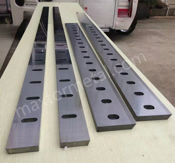
Jawaban Cepat: Pisau potong inlaid tungsten carbide biasanya memberikan masa pakai bilah 2–3,5 kali lebih lama dibandingkan pisau D2 pada lini AHSS. ROI didorong terutama oleh berkurangnya frekuensi penggantian pisau dan penurunan scrap akibat ketidakstabilan tepi potong—bukan hanya dari harga pisau itu sendiri. Pengendalian celah (clearance) dan restorasi geometri pengasahan ulang yang konsisten adalah dua variabel utama yang menentukan apakah penggandaan masa pakai tersebut dapat dipertahankan dalam produksi.
Lini AHSS/UHSS berkapasitas ultra-tinggi biasanya tidak gagal karena mesin potong «tidak mampu memotong». Kegagalan terjadi karena ketidakstabilan kecil — gopel pada tepi potong, pergeseran tinggi burr, variasi celah (clearance) saat beban kerja, atau geometri pengasahan ulang yang tidak konsisten — yang secara perlahan berubah menjadi downtime, scrap, dan penurunan OEE.
Panduan ini ditujukan bagi manajer produksi & pemeliharaan, insinyur proses, dan pembeli teknis yang mengoperasikan (atau sedang meng-upgrade) lini cut-to-length (CTL) dan mesin potong guillotine untuk material AHSS. Jika Anda sedang mengevaluasi pisau inlaid carbide, tujuannya bukanlah sekadar mengejar peningkatkan «masa pakai», melainkan membangun kalkulasi ROI yang andal dan dapat dipertanggungjawabkan saat bauran grade material, waktu changeover, dan durasi pengasahan ulang diperhitungkan.
Untuk referensi mengenai konfigurasi mata pisau pemotong dan format pemesanan yang umum, Anda dapat mulai dengan Pisau pemotong Maxtor Metal halaman—lalu gunakan model dan poin pemeriksaan di bawah ini untuk memvalidasi kesesuaian dan aspek ekonomi untuk lini produk spesifik Anda.
- Panduan ini ditujukan untuk siapa dan dalam konteks AHSS/UHSS.
- Perubahan ultra-berkecepatan tinggi apa yang terjadi pada pemilihan dan perawatan bilah?
- Bagaimana mata pisau gunting bertatahkan tungsten karbida memengaruhi masa pakai, pengendalian gerinda, dan TCO (Total Cost of Ownership).
Pada material AHSS, jendela pemotongan (cutting window) makin menyempit karena kekuatan bahan yang tinggi, panas dan adhesi yang makin parah, serta akumulasi toleransi (defleksi mesin + klem + keselarasan/paralelisme) menjadi lebih krusial. Panduan AHSS dari WorldAutoSteel mencatat bahwa celah potong (clearance) biasanya meningkat seiring bertambahnya kekuatan material—naik dari sekitar 6% ketebalan untuk baja lunak (mild steel) menjadi sekitar 16% atau lebih tinggi ketika kekuatan tarik (tensile strength) melebihi ~1400 MPa—dan mereka juga menekankan bahwa tinggi burr kurang andal sebagai indikator keausan pada AHSS dibandingkan pada baja lunak (sehingga pemantauan kualitas tepi potong menjadi jauh lebih penting).
Yang berubah pada kapasitas ultra-tinggi sangatlah sederhana: Anda tidak hanya membutuhkan pisau yang «lebih keras». Anda memerlukan sistem que menjaga kestabilan tepi potong di antara jadwal pemeliharaan terencana — interval pengasahan ulang yang terprediksi, persiapan tepi potong (edge prep) yang terkontrol, serta loop QC yang mencegah pergeseran geometri antar-batch.
Mata pisau geser bertatahkan karbida tungsten sering dievaluasi karena tiga alasan praktis:
- Stabilitas masa pakai pada teknologi mutakhir. (terutama ketika kemiringan dan kondisi permukaan bervariasi)
- Kontrol gerinda dari waktu ke waktu (penyimpangan berkurang seiring tumpulnya mata pisau)
- Biaya kepemilikan total (TCO) yang lebih rendah saat Anda memperhitungkan pergantian, penggilingan ulang, dan sisa material.
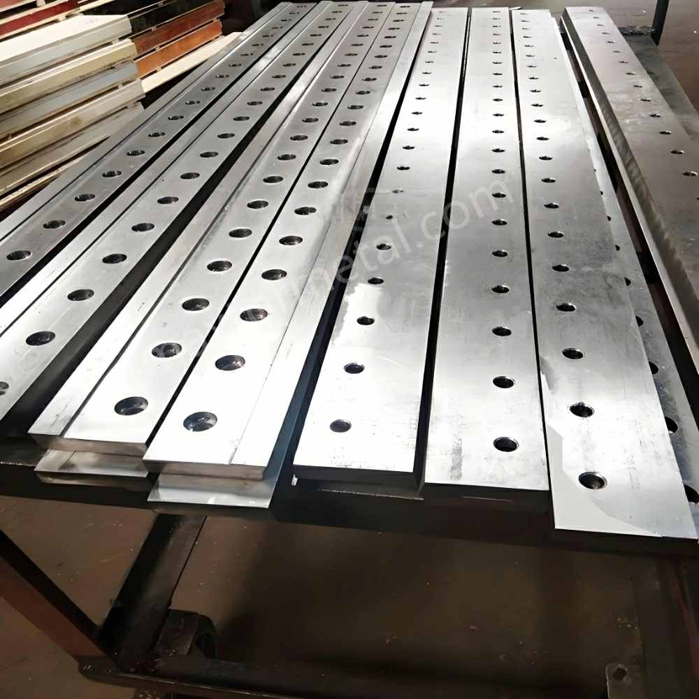
Catatan Teknik: Mata pisau geser bertatahkan karbida tungsten adalah alat potong presisi di mana tepi karbida tungsten yang disolder terintegrasi ke dalam badan baja paduan D2 atau H13, menggabungkan ketangguhan baja perkakas dengan ketahanan aus karbida pada permukaan pemotong. Untuk jalur pemotongan AHSS dan UHSS, konstruksi ini memperpanjang stabilitas tepi antara proses pengasahan ulang dan mengurangi pergeseran gerinda di bawah kondisi permukaan dan kemiringan yang bervariasi—asalkan kontrol jarak bebas, penyelarasan, dan pemulihan geometri pengasahan ulang tetap terjaga. [→ Lihat ikhtisar teknis mata pisau geser Maxtor Metal]
Benchmark Performa Pisau Potong Inlaid Tungsten Carbide
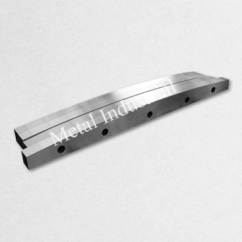
Pengganda umur vs baja D2/vanadium tinggi
Mata pisau bertatahkan karbida biasanya memberikan pengembalian investasi (ROI) ketika mode kegagalan Anda saat ini adalah... kerusakan tepi (pengikisan mikro, keausan yang dipercepat di tepi, ketidakstabilan gerinda) daripada kerusakan mekanis yang terjadi sekali saja.
Alih-alih mengandalkan klaim universal "umur X kali lipat", gunakan dua indikator yang dapat diukur pada tanaman sebagai tolok ukur:
- Meter (atau ton) per ujung tajam sampai pemicu kualitas Anda tercapai
- Stabilitas waktu pemicu di seluruh campuran tingkatan (mata pisau yang sama seharusnya tidak berperilaku seperti dua alat yang berbeda ketika Anda beralih dari HSLA ke AHSS)
Cara yang berguna untuk membandingkan dengan baja perkakas D2 atau baja perkakas vanadium tinggi adalah dengan menjalankan uji coba terkontrol pada 2–3 jenis baja terbaik Anda dan satu kondisi "terburuk" (bahan berlapis, kerak permukaan yang lebih tinggi, atau proses hilir yang paling sensitif terhadap gerinda). Model ROI di bagian selanjutnya dari panduan ini akan memungkinkan Anda untuk mengkonversi rasio umur pakai yang diamati menjadi biaya per meter/ton.
Kedalaman tatahan, penyelesaian tepi, dan target pengasah mikro.
Untuk garis AHSS, tepinya melakukan dua fungsi sekaligus: harus tahan terhadap keausan abrasif/perekat sekaligus tetap cukup kuat untuk menghindari pengelupasan yang rapuh.
Tiga parameter cenderung mendominasi hasil:
- Kedalaman tatahanInlay yang lebih dalam umumnya mendukung lebih banyak penggerindaan ulang total sebelum batas inlay tercapai.
- Penyelesaian tepi: Kualitas permukaan pada bidang pemotongan memengaruhi gesekan, pembangkitan panas, dan daya rekat.
- Pengasah mikroPengasahan mikro yang terkontrol mengurangi "kerapuhan ujung pisau" dan dapat meningkatkan stabilitas mata pisau, terutama ketika jarak bebas tidak sepenuhnya seragam di sepanjang panjangnya.
Nilai target terbaik bergantung pada ketebalan, kekuatan, dan apakah jalur produksi Anda dibatasi oleh gerinda atau geometri. Kuncinya adalah menentukan kriteria penerimaan (lihat bagian QC) agar hasil pengasahan ulang tidak secara diam-diam menggeser alat pengasah mikro dan mengubah perilaku gerinda Anda.
Sebagai referensi umum, lebar sisipan dalam kisaran 3–6 mm umum digunakan untuk mata pisau pemotong guillotine dan CTL; kedalaman sisipan ditentukan oleh toleransi ketebalan mata pisau dan jumlah total siklus pengasahan ulang yang dibutuhkan.
Di Maxtor Metal, mata pisau geser bertatahkan karbida diproduksi dengan geometri tatahan yang terdokumentasi dan catatan penyelesaian permukaan setelah penggerindaan, memastikan spesifikasi pengasahan mikro dan permukaan pemotong yang ditetapkan di pabrik dapat dilacak melalui siklus penggerindaan ulang.
Pemicu interval penggilingan ulang dan jumlah tipikal
Pada baja lunak, ketinggian gerinda sering meningkat seiring dengan keausan dan dapat menjadi pemicu yang mudah. Pada AHSS, Pedoman AHSS WorldAutoSteel mencatat bahwa ketinggian gerinda mungkin tetap relatif konstan bahkan saat perkakas aus, itulah sebabnya set pemicu yang lebih lebar lebih aman.
Menggunakan dua pemicu: satu untuk kualitas tepi dan satu untuk mempertaruhkan.
- Pemicu kualitas tepi (pilih apa yang paling dirugikan oleh proses hilir Anda):
- pergeseran kekasaran zona patahan
- transisi polesan/patahan yang tidak merata
- Terlihat adanya retakan mikro atau garis-garis yang berkorelasi dengan pergeseran gerinda.
- Pemicu risiko:
- Meningkatnya waktu peralihan karena perebutan posisi.
- meningkatkan frekuensi penyesuaian untuk menjaga toleransi
- Peningkatan kejadian barang rusak terkonsentrasi setelah perubahan mutu.
Kumpulan pemicu ini dipetakan langsung ke kueri pencarian umum seperti interval pengasahan ulang pisau pemotong dan membantu Anda menstandarisasi kapan operator harus melakukan intervensi.
Jumlah total pengasahan ulang biasanya bervariasi tergantung pada kedalaman tatahan, toleransi ketebalan mata pisau, dan seberapa presisi geometri dipulihkan setiap siklus. Intinya: Anda harus dapat memprediksi kisaran jumlah siklus yang diharapkan. sebelum Anda berkomitmen, karena model ROI bergantung pada hal itu.
Pengaturan dan Pengendalian Kegagalan
Pengaturan (setup) adalah tempat sebagian besar ROI (Return on Investment) diperoleh atau hilang. Blade premium yang digunakan dalam pengaturan drifting akan menjadi komponen habis pakai yang mahal.
Jika keluhan utama Anda adalah pengendalian gerinda pada pemotongan AHSS Saat melakukan pemotongan, dua tuas yang biasanya paling penting adalah (1) menjaga keseragaman jarak bebas dari ujung ke ujung dan (2) menjaga konsistensi persiapan tepi setelah setiap pengasahan ulang. Ambil sampel tampilan zona tepi pada irama tetap (berdasarkan jumlah lilitan atau pergeseran) dan korelasikan dengan frekuensi penyesuaian dan kejadian pengasahan ulang.
Target jarak aman untuk AHSS tipis dan baja tahan karat
Untuk AHSS dan stainless steel tipis, pertimbangkan jarak bebas sebagai persentase dari ketebalan, Kemudian, pastikan bahwa ukurannya tetap konsisten dari ujung ke ujung di bawah penjepitan sebenarnya.
WorldAutoSteel's Pedoman AHSS Membahas bahwa celah umumnya meningkat seiring dengan kekuatan (dari ~6% hingga ~16%+ pada rezim kekuatan yang lebih tinggi), dan juga memperingatkan bahwa celah yang terlalu kecil dan terlalu besar menciptakan mode kegagalan yang berbeda.
Target praktis untuk memulai (kemudian validasi dengan potongan uji dan inspeksi tepi):
- Jarak bebas pisau pemotong AHSS: mulai dari Ketebalan 10–16% rentang untuk kekuatan yang lebih tinggi, dan sesuaikan berdasarkan tampilan tepi dan sensitivitas retak.
- Baja tahan karat (ketebalan tipis): sering membutuhkan jarak bebas lebih tinggi daripada baja lunak untuk menghindari geser ganda dan pengerasan kerja yang berlebihan; validasi dengan tampilan zona tepi dan perilaku gerinda.
Poin PentingDalam AHSS, jangan hanya menganggap tinggi gerinda sebagai sinyal "jarak bebas sudah tepat"—pantau perilaku dan stabilitas zona tepi potong secara keseluruhan dari waktu ke waktu.
Penyelarasan, sudut kemiringan, dan penjepitan yang seragam
Jika Anda hanya menerapkan satu perubahan disiplin untuk AHSS, jadikan ini sebagai pilihan: Perlakukan paralelisme dan keseragaman penjepitan sebagai variabel kualitas, bukan variabel pemeliharaan..
- Penyelarasan: verifikasi kesejajaran di beberapa titik sepanjang panjang bilah, bukan hanya di ujungnya.
- Sudut kemiringan: pilih strategi kemiringan yang sesuai dengan campuran material Anda; sudut ekstrem dapat mengurangi gaya tetapi juga dapat mengubah pola deformasi pada material tipis.
- Penjepitan: penjepitan yang tidak seragam menciptakan lonjakan celah lokal; lonjakan tersebut cenderung terjadi di tempat terjadinya pengikisan dan di mana pergeseran gerinda menjadi "misterius."“
Strategi pemanasan, adhesi, dan persiapan tepi.
AHSS dan stainless steel memperparah dua masalah: panas dan adhesi.
- Panas: beban yang lebih tinggi ditambah gesekan dapat melunakkan zona lokal dan mempercepat keausan; panas juga memperbesar risiko pengelupasan mikro ketika tepinya terlalu tajam.
- Daya rekat: khususnya baja tahan karat dapat "menempel" dan mengolesi; hal itu mengubah jarak bebas efektif dan dapat menyebabkan bekas pada tepi.
Strategi persiapan yang cenderung menstabilkan perilaku:
- Gunakan pengasah mikro yang terkontrol daripada mata pisau cukur yang rapuh.
- Jaga agar permukaan pemotong tetap konsisten dalam hasil akhir setelah setiap pengasahan ulang.
- Jika masalah utamanya adalah daya rekat, fokuslah pada kondisi permukaan dan disiplin pembersihan (lapisan perekat menjadi perubahan geometri).
Protokol Pengasahan Ulang dan Control Kualitas (QC)
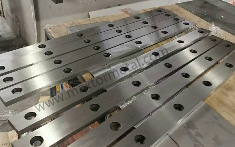
Batas inlay, langkah penggerindaan ulang, dan total siklus yang diizinkan
Inlay karbida mengubah pertanyaan tentang pengasahan ulang dari “berapa kali kita bisa mengasah?” menjadi “berapa kali kita bisa mengasah?” sebelum kita mengkompromikan sistem inlay?”
Protokol Anda harus mendefinisikan:
- kedalaman inlay minimum yang tersisa (titik berhenti)
- kehilangan ketebalan maksimum yang diperbolehkan per penggilingan ulang
- bagaimana Anda mempertahankan persiapan tepi (pengasahan mikro) di seluruh siklus
- Aturan untuk menentukan kapan mata pisau "dapat diasah ulang" versus "rusak" (retak, masalah integritas pengelasan, hilangnya geometri).
Untuk metode perhitungan shim yang digunakan untuk mengkompensasi kehilangan ketebalan setelah setiap siklus penggilingan ulang, lihat panduan kompensasi pengurangan ketebalan penggilingan ulang dan tumpukan shim.
Restorasi geometri, penyelesaian permukaan (Ra), dan kriteria penerimaan.
Penggerindaan ulang ROI hanya berfungsi jika pemulihan geometri dilakukan dengan disiplin.
Kategori kriteria penerimaan yang direkomendasikan:
- Geometri
- kelurusan di sepanjang tepi pemotong
- kesejajaran di sepanjang panjangnya
- geometri bevel yang konsisten (tidak ada penyimpangan "sudut lunak")
- Lapisan permukaan
- Kekasaran permukaan pemotongan harus terkontrol dan dapat diulang (lacak Ra atau ukuran kekasaran permukaan yang setara).
- Kondisi tepi
- tidak ada pemasangan microchip di luar ambang batas yang telah Anda tetapkan
- pengasahan mikro yang konsisten (jangan biarkan kecenderungan "semakin tajam setiap saat")
Protokol penerimaan pasca-penggilingan Maxtor Metal mencakup ketiga kategori di atas—geometri, penyelesaian permukaan, dan kondisi tepi—dengan catatan inspeksi yang dapat dilacak yang dikembalikan bersama setiap batch penggilingan ulang.
Untuk dokumentasi persyaratan tepi pada gambar, standar untuk menunjukkan persyaratan tepi yang tidak terdefinisi dalam dokumentasi produk teknis adalah ISO 13715:2017. Bahkan jika Anda tidak menggunakan simbol tersebut secara langsung, menyelaraskan bahasa penerimaan internal Anda dengan standar yang diakui akan mengurangi ambiguitas antara shift kerja, pemasok, dan vendor bahan daur ulang.
Maxtor Metal mendukung pembuatan mata pisau bertatahkan karbida dengan pemeriksaan QC dalam proses dan dapat menyediakan layanan pengasahan ulang dengan catatan inspeksi yang dapat dilacak, yang membantu menjaga geometri dan konsistensi batch tetap terkendali.
Dokumentasi, MTC, dan pemeriksaan konsistensi batch
Untuk lini AHSS, risiko pengadaan seringkali tersembunyi dalam variasi: sama Nomor komponen berperilaku berbeda di setiap batch.
Paket dokumentasi praktis untuk setiap kelompok harus mencakup:
- MTC / ketertelusuran material untuk badan dasar dan bahan inlay jika berlaku.
- bukti kekerasan / perlakuan panas jika relevan
- Laporan inspeksi untuk dimensi-dimensi utama (ketebalan, kelurusan, kesejajaran)
- Catatan riwayat penggilingan ulang (jumlah siklus, stok yang dikeluarkan, inspeksi pasca penggilingan)
Ini tidak harus birokratis. Intinya adalah untuk mempercepat pencarian akar penyebab ketika Anda melihat penyimpangan gerinda atau pengelupasan: Anda dapat memisahkan masalah pengaturan dari variasi batch.
Model TCO dan ROI
Input, rumus, dan logika amortisasi
Struktur TCO di bawah ini mencerminkan bagaimana Maxtor Metal membingkai percakapan biaya dengan jalur AHSS berkinerja tinggi: total biaya per meter, bukan harga blade.
Model ROI yang bermanfaat mengubah “umur pakai mata pisau” menjadi biaya per meter (atau biaya per ton) dan menambahkan biaya yang biasanya mendominasi pada lini produksi berkapasitas tinggi: waktu henti dan limbah.
Ini adalah tulang punggung untuk hal yang praktis. total biaya kepemilikan untuk mata pisau pemotong perbandingan, karena memaksa setiap asumsi (masa pakai, penggilingan ulang, menit pergantian) ke dalam satuan yang sama.
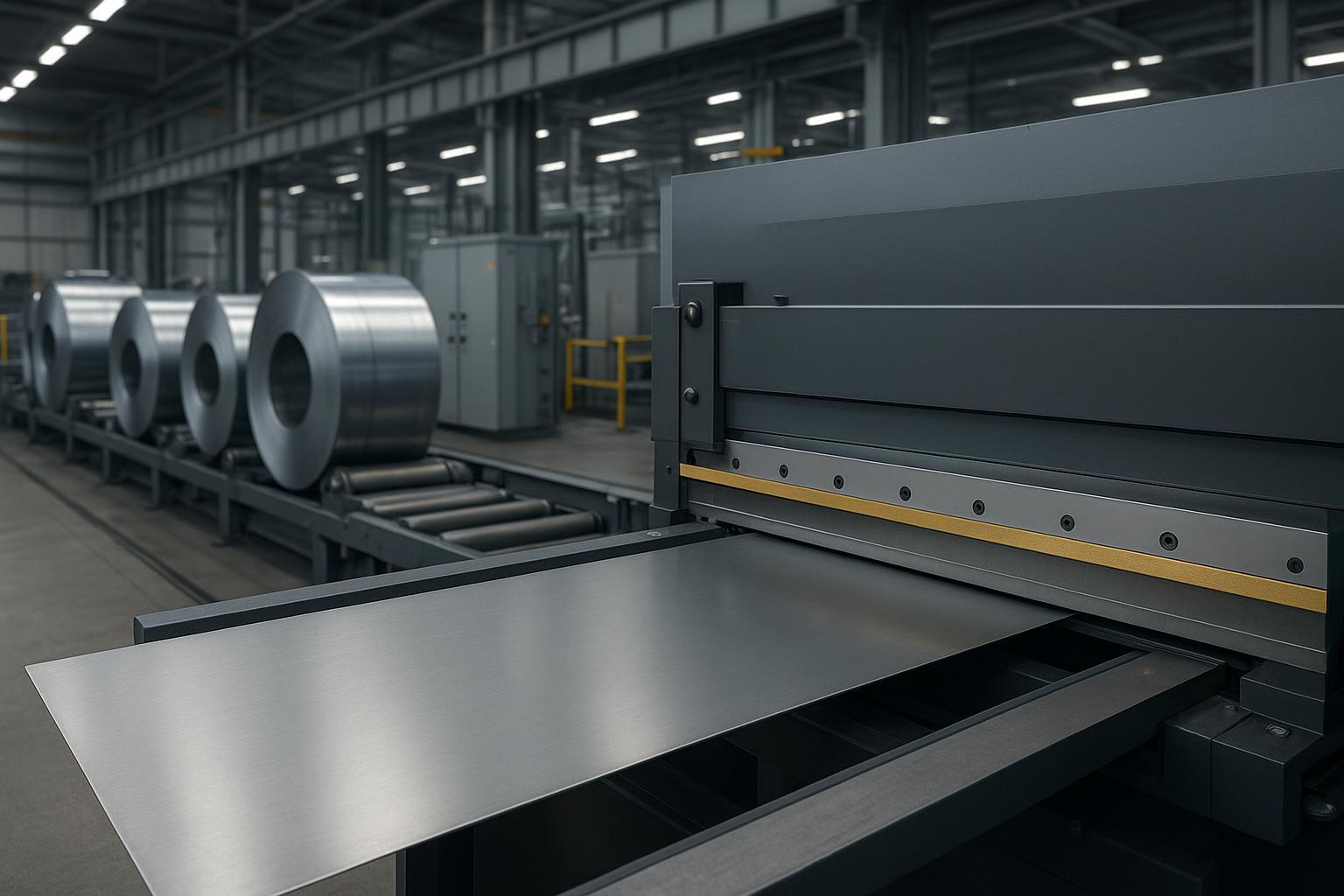
Definisikan input-input ini:
C_blade: biaya pembelian satu set pisauN_tepi: jumlah sisi yang dapat digunakan per set (termasuk pembalikan/rotasi jika berlaku)Langkan: meter (atau ton) per sisi antara pengasahan ulang/penggantianN_regrinds: jumlah total material yang dapat digiling ulang sebelum menjadi barang rongsokan (dibatasi oleh batas tatahan + toleransi geometri)C_regrind: biaya per siklus penggilingan ulangT_perubahan: waktu pergantian per acara (jam)C_downtime: biaya waktu henti (downtime) per jam dengan beban penuhC_scrap: biaya barang rongsokan/perbaikan per ton (atau per meter)S_scrap: tingkat kerusakan yang disebabkan oleh ketidakstabilan tepi pemotongan (sebagai pecahan)
Struktur amortisasi yang sederhana:
- Amortisasi bilah per meter
Salin dan tempel templat kalkulator ROI
Jika Anda menginginkan templat yang mudah dipindahkan ke Excel, mulailah dengan tabel ini dan isi data baris Anda sendiri. Jaga agar satuan tetap konsisten (meter). atau ton) di setiap baris.
| Masukan | Simbol | Nilai Anda | Satuan / catatan |
|---|---|---|---|
| Biaya pembelian set pisau | C_blade | $ per set | |
| Tepi yang dapat digunakan per set | N_tepi | hitung (termasuk putaran/rotasi) | |
| Nyawa per tepi untuk memicu | Langkan | meter/tepi atau ton/tepi | |
| Total bahan daur ulang sebelum menjadi barang rongsokan | N_regrinds | jumlah (dibatasi oleh tatahan + toleransi) | |
| Biaya penggilingan ulang per siklus | C_regrind | $ per penggilingan ulang | |
| Waktu pergantian per acara | T_perubahan | jam/acara | |
| Biaya waktu henti | C_downtime | $/jam (muatan penuh) | |
| Biaya besi tua | C_scrap | $/ton atau $/meter | |
| Tingkat kerusakan akibat ketidakstabilan tepi pemotongan | S_scrap | pecahan (misalnya, 0,009 = 0,9%) | |
| Keluaran | Rumus | Hasil | Catatan |
| — | — | — | — |
| Total umur pakai per set mata pisau | Total_m | N_tepi × L_tepi × (N_penggilingan ulang + 1) | Gunakan satuan meter atau ton secara konsisten. |
| Amortisasi bilah per unit | Biaya_mata_per_meter | C_blade / Total_m | $/meter atau $/ton |
| Biaya penggilingan ulang per unit | Biaya_penggilingan_ulang_per_meter | (C_regrind × N_regrinds) / Total_m | $/meter atau $/ton |
| Biaya waktu henti per unit | Biaya_turun_per_m | (T_perubahan × C_waktu henti × (N_penggilingan ulang + 1)) / Total_m | Disederhanakan; tambahkan acara tambahan jika tidak direncanakan. |
| Biaya sisa per unit | Biaya_skrap_per_m | S_scrap × C_scrap | Konversikan satuan jika diperlukan. |
| Total biaya per unit | TCO_per_m | Jumlah semua biaya di atas | Bandingkan kondisi dasar dengan yang bertatahkan karbida. |
Tata letak ini memudahkan untuk menjalankan model yang sama untuk skenario dasar dan skenario dengan lapisan karbida, kemudian menghitung perbedaannya (pengurangan TCO, periode pengembalian investasi, dan ROI).
Biaya_mata_per_meter = C_mata / (N_ujung × L_ujung × (N_pengasahan ulang + 1))- Biaya penggilingan ulang per meter
Biaya_penggilingan_ulang_per_m = (C_penggilingan_ulang × N_penggilingan_ulang) / (N_tepi × L_tepi × (N_penggilingan_ulang + 1))
- Biaya waktu henti per meter (pergantian + penggilingan ulang)
Biaya_turun_per_meter = (Perubahan_suhu × Waktu_turun_biaya × Total_kejadian) / Total_meter
Kemudian tambahkan sisa bahan:
Biaya_limbah_per_m = S_limbah × C_limbah(konversikan satuan secara konsisten)
Perbandingan ROI adalah selisihnya:
ROI = (TCO_dasar - TCO_karbida) / Delta_Investasi
Contoh biaya per meter/ton dengan tempat penampung
Berikut ini adalah contoh yang telah dikerjakan. contoh Gunakan nilai sampel untuk menunjukkan bagaimana perhitungan matematisnya berjalan. Ganti angka-angka tersebut dengan data baris Anda sendiri.
Menganggap:
C_blade = $6,000per setN_tepi = 2L_edge = 200.000 mJumlah penggilingan ulang = 6C_regrind = $450
Jumlah meter per set sepanjang masa pakai:
Total_m = N_tepi × L_tepi × (N_penggilingan ulang + 1) = 2 × 200.000 × 7 = 2.800.000 m- Amortisasi bilah per meter:
$6,000 / 2,800,000 = $0.00214/m
- Biaya penggilingan ulang per meter:
($450 × 6) / 2.800.000 = $0,00096/m
Jika biaya dominan Anda adalah waktu henti (downtime), Anda akan melihat ROI (Return on Investment) berfluktuasi secara signifikan seiring dengan waktu peralihan.
Contoh input waktu henti:
Perubahan suhu = 0,5 jamper acaraC_downtime = $3,000/jamJumlah_kejadian = 7(awal + 6 kali penggilingan ulang)
Biaya waktu henti per meter:
($3,000 × 0.5 × 7) / 2,800,000 = $0.00375/m
Contoh sederhana ini menunjukkan mengapa “harga satuan mata pisau” seringkali bukanlah faktor penentu—Jam peralihan dan peristiwa stabilitas adalah.
Sensitivitas terhadap kontrol celah, campuran mutu, dan SLA hasil penggilingan ulang
Tiga tuas sensitivitas biasanya mendominasi:
- Kontrol celah (keseragaman jarak bebas)
- Kontrol gap yang buruk dapat menghapus perolehan nyawa dengan memicu chipping dan memaksa pengulangan grinding lebih awal.
- Campuran mutu (kekuatan + kondisi permukaan)
- Jika jadwal Anda bergeser ke arah AHSS dengan kekuatan lebih tinggi atau kondisi permukaan yang lebih abrasif, stabilitas tepi menjadi lebih berharga.
- Regrind SLA (waktu penyelesaian + konsistensi)
- Proses penggilingan ulang yang lambat atau tidak konsisten meningkatkan kebutuhan inventaris suku cadang dan meningkatkan kemungkinan terjadinya penyimpangan geometri.
Jika Anda menginginkan satu output sensitivitas yang "ramah keuangan", modelkan TCO di bawah tiga skenario (konservatif / yang diharapkan / optimis) dengan hanya memvariasikan:
Langkan(kehidupan)T_perubahan(waktu pergantian)S_scrap(sisa yang disebabkan oleh ketidakstabilan tepi)
Cara yang tepat untuk menyajikan sensitivitas—tanpa melakukan overfitting—adalah dengan hanya memvariasikan asumsi yang biasanya mendominasi TCO untuk lini produksi berkapasitas tinggi.
| Skenario | Umur per tepi L_edge | Waktu peralihan T_change | Scrap dengan ketidakstabilan tepi S_scrap | Apa yang diwakilinya |
|---|---|---|---|---|
| Konservatif | batas bawah pita pilot Anda | batas atas dari perubahan yang Anda amati | batas atas dari sisa-sisa yang terkait dengan tepi | Pengaturan penyimpangan, kondisi permukaan yang lebih kasar, waktu pengerjaan ulang yang lebih lambat. |
| Mengharapkan | median pita pilot | perubahan median | atribusi barang rongsokan median | Ritme operasi normal dan campuran tingkat |
| Optimis | batas atas pita pilot | peralihan batas bawah (SOP praktik terbaik) | atribusi sisa batas bawah | Kontrol jarak bebas yang ketat + hasil penggilingan ulang yang konsisten + material yang stabil |
Saat Anda mempresentasikan hasilnya, tunjukkan rentang (bukan estimasi titik tunggal) untuk TCO per meter/ton dan menit waktu henti yang dihindari. Ini biasanya membuat studi kelayakan bisnis lebih kredibel daripada angka ROI tunggal.
Panduan Praktis Implementasi
SOP untuk logistik pergantian, inspeksi, dan penggilingan ulang
Tiga SOP di bawah ini berlaku di semua konteks uji coba dan harus diselesaikan sebelum Anda meningkatkan skala ke produksi penuh.
Untuk SOP (Prosedur Operasi Standar) lengkap berbasis pengukuran mengenai pengambilan keputusan rotasi dan pengasahan ulang yang berlaku untuk mata pisau pemotong guillotine—termasuk pita ambang batas gerinda, urutan penggunaan tepi, dan templat log yang siap diaudit—lihat Prosedur Operasi Standar (SOP) untuk jadwal rotasi pisau bolak-balik 4 sisi dan kriteria pengasahan ulang..
Hasil Uji Coba: Rangkuman Tiga Studi Kasus Anonim
Cara tercepat untuk mempertahankan keputusan ROI adalah dengan melakukan uji coba kecil dan terkontrol, lalu melaporkan hasilnya dalam satuan yang sama dengan yang sudah dipantau pabrik Anda: jumlah gulungan antara proses penggilingan ulang, stabilitas gerinda, intervensi pengaturan, limbah/pengerjaan ulang, dan menit OEE.
Di bawah ini adalah tiga pilot anonim yang menggambarkan di mana mata pisau bertatahkan karbida cenderung memberikan keuntungan lebih dulu. Gunakanlah sebagai panduan. struktur, bukan sebagai janji—hasil Anda akan bergantung pada campuran mutu, kontrol jarak bebas, pengulangan penjepitan, dan konsistensi penggilingan ulang.
Studi Kasus Percontohan 1 — AHSS CTL pada DP980
Konteks
- Bahan: DP980 (980–1000 MPa)
- Ketebalan: 1,2–2,0 mm
- Jalur: Coil-to-Length (CTL)
- Kondisi kumparan: Diasamkan & Diminyaki, kerak pabrik ringan+
- Mata pisau: Mata pisau bertatahkan karbida: Badan D2 + tepi WC ultra-halus yang dilas, dipasok oleh Maxtor Metal
Konfigurasi dasar vs konfigurasi bertatahkan karbida
- Mata pisau standar: Baja perkakas D2, 60–61 HRC
- Bilah bertatahkan karbida: Badan D2 (59–60 HRC) + tepi WC ultra-halus yang disolder
- Lebar karbida: 4 mm
- Kekerasan tepi: ~89 HRA
Pemicu dan pengukuran
- Pemicu setelah sekitar 40-50 lilitan pada kondisi awal:
- Tinggi gerinda mendekati 0,10 mm
- meningkatkan frekuensi penyesuaian jarak bebas bilah
- pengecekan ulang bagian pertama yang lebih sering
- Urutan pengukuran:
- per kumparan: tinggi gerinda diukur di kiri/tengah/kanan menggunakan mikroskop pembuat alat 50×
- setiap 10 lilitan: catat gerinda maksimum, jarak bebas, dan radius tepi
Hasil uji coba
| KPI | Garis dasar D2 | WC bertatahkan |
|---|---|---|
| Umur bilah pisau | 1.0× | 2.9× |
| Kumparan di antara hasil penggilingan ulang | 48 | 138 |
| Rata-rata gerinda | 0,082 mm | 0,039 mm |
| Peristiwa penyiapan yang tidak direncanakan | 5/bulan | 2/bulan |
| Membatalkan | 1.8% | 0.9% |
| OEE | 84.1% | 87.6% |
| Regrind SLA | — | 5 hari kerja |
Apa yang diajarkan pilot ini?
- Sifat abrasif DP980 menjadikan stabilitas keausan tepi sebagai prioritas utama.
- Mempertahankan pengaturan jarak bebas yang sama seperti yang digunakan untuk D2 awalnya menyebabkan pengelupasan mikro lokal; optimasi jarak bebas kecil mengembalikan perilaku yang stabil.
Studi Kasus Percontohan 2 — Jalur pemotongan guillotine dengan timbangan pabrik yang berat
Konteks
- Bahan: Baja tahan karat AHSS canai panas
- Ketebalan: 4–8 mm
- Baris: Guillotine hidrolik
- Permukaan: kerak pabrik yang tebal
- Mata pisau: Mata pisau bertatahkan karbida: Badan H13 + tepi WC ultra-halus yang dilas, dipasok oleh Maxtor Metal
Konfigurasi dasar vs konfigurasi bertatahkan karbida
- Pisau dasar: H13 yang dimodifikasi
- Bilah bertatahkan karbida: Badan H13 + tepi karbida tungsten yang dilas; ditempa ganda.
Pemicu dan pengukuran
- Keausan akibat kerak meningkatkan gerinda dan memaksa penyesuaian pengaturan yang sering.
- Pengukuran:
- per shift: periksa gerinda, radius tepi, dan suhu mata pisau.
- mingguan: periksa kelurusan dan kerataan
Hasil uji coba
| KPI | Sebelum | Setelah |
|---|---|---|
| Umur bilah pisau | 1.0× | 2.1× |
| Perubahan bilah bulanan | 4 | 2 |
| Waktu penyiapan | 150 menit/bulan | 70 menit/bulan |
| Mengolah lagi | 2.4% | 1.3% |
| Pengelupasan tepi | sesekali | berkurang secara signifikan |
| Regrind SLA | — | 7 hari kalender |
Apa yang diajarkan pilot ini?
- Kerak pabrik tetap menjadi sumber keausan utama. Karbida meningkatkan ketahanan aus, tetapi tanpa penghilangan kerak, pengali umur lebih rendah daripada dalam kondisi yang diasamkan/diminyaki.
Studi Kasus Percontohan 3 — CTL otomotif bervolume tinggi
Konteks
- Bahan: CP780 + DP780
- Ketebalan: 1,6–2,5 mm
- Jalur: CTL kecepatan tinggi
- Produksi tahunan: >60.000 ton
- Mata pisau: Mata pisau bertatahkan karbida: Badan D2 + tepi WC ultra-halus yang dilas, dipasok oleh Maxtor Metal
Konfigurasi dasar vs konfigurasi bertatahkan karbida
- Mata pisau standar: D2 premium
- Spesifikasi karbida: WC butiran halus, disolder vakum
- Target penyelesaian permukaan setelah penggerindaan: Ra ≤ 0,2 μm
Pemicu dan pengukuran
- Kecepatan kerja yang tinggi memerlukan penghentian mingguan yang direncanakan; gerinda mulai memengaruhi kualitas pengelasan di tahap selanjutnya.
- Pengukuran:
- bagian pertama: tinggi gerinda
- setiap 20 lilitan: pemeriksaan mikroskop, jarak bebas, radius tepi
- Setiap proses pengasahan ulang: kerataan, kesejajaran, ketebalan.
Hasil uji coba
| KPI | Sebelum | Setelah |
|---|---|---|
| Umur bilah pisau | 1.0× | 3.4× |
| Interval penggilingan ulang | 2 minggu | 7 minggu |
| Max burr | 0,11 mm | 0,05 mm |
| Waktu henti yang direncanakan | 9 jam/bulan | 4 jam/bulan |
| Klaim keunggulan pelanggan | 3/kuartal | 0–1/kuartal |
| Perkiraan Total Biaya Kepemilikan (TCO) | garis dasar | Pengurangan ~18% (amortisasi bilah + penggilingan ulang + input pergantian; dihitung menggunakan model TCO di atas) |
| Regrind SLA | — | 3–4 hari kerja |
Apa yang diajarkan pilot ini?
- Jadwal rotasi tetap + pengasahan ulang ditambah pemeriksaan pemasangan ulang (paralelisme + jarak bebas) mencegah variasi pemasangan menutupi perbedaan perkakas. Pengurangan TCO ~18% terutama didorong oleh perpanjangan interval pengasahan ulang (2 minggu → 7 minggu) dan pengurangan waktu henti yang direncanakan (9 jam/bulan → 4 jam/bulan), dengan amortisasi bilah memberikan kontribusi yang lebih kecil pada tingkat throughput ini.
Catatan pilot sederhana yang dapat Anda salin
Rangkum naskah pilot dalam satu lembar agar bagian keuangan dan produksi menggunakan bahasa yang sama:
- kelas(kelas) + rentang ketebalan + kondisi permukaan
- meter/ton/gulungan untuk memicu (kualitas tepi + pemicu risiko)
- menit pergantian per acara (median dan terburuk 10%)
- Kerusakan/pengerjaan ulang yang disebabkan oleh ketidakstabilan mata pisau
- SLA penggilingan ulang (hari) dan hasil penerimaan pasca-penggilingan ulang
- catatan tentang pengaturan jarak bebas, pengulangan penjepitan, dan setiap perubahan pengaturan selama uji coba.
Perlakukan mata pisau sebagai bagian dari proses yang terkontrol, bukan sebagai barang habis pakai:
- SOP Penggantian: pola torsi, inspeksi klem, titik verifikasi paralelisme
- SOP Inspeksi: tentukan pemicu kualitas tepi yang memaksa tindakan (bukan hanya "terlihat kusam")
- SOP logistik penggilingan ulang: pemberian label, penghitungan siklus, dan pemeriksaan penerimaan pasca-penggilingan ulang
Pengambilan data, dasbor, dan KPI untuk OEE dan kualitas.
Jika Anda tidak mengukurnya, Anda tidak dapat mempertahankan ROI (Return on Investment).
KPI Praktis:
- meter/ton per tepi untuk memicu
- distribusi jumlah siklus penggilingan ulang (apakah Anda secara konsisten mencapai rentang yang diharapkan?)
- waktu peralihan (median + terburuk 10%)
- Kejadian barang rusak/pengerjaan ulang terkait dengan masalah gerigi/tepi.
- Menit kehilangan OEE yang disebabkan oleh pemotongan (bukan "pemeliharaan" umum)
Dasbor tidak harus rumit. Laporan mingguan sederhana yang menghubungkan peristiwa pengasahan ulang dengan menit OEE dan limbah sudah cukup untuk memvalidasi apakah mata pisau bertatahkan karbida memberikan pengembalian investasi.
Evaluasi pemasok dan kriteria SLA untuk ujung karbida dan pengelasan.
Untuk mata pisau bertatahkan karbida, evaluasi pemasok harus fokus pada... pengulangan sebanyak bahan-bahan.
Kriteria utama:
- Integritas dan konsistensi tatahan (kontrol proses dan bukti inspeksi)
- toleransi geometri dan metode inspeksi yang terdokumentasi
- kemampuan penggilingan ulang dan batasan yang ditetapkan (apa aturan penghentiannya?)
- Kejelasan SLA: waktu penyelesaian, opsi percepatan, dan komitmen konsistensi
- Ketertelusuran: MTC dan catatan batch
Before committing to carbide-inlaid blades, confirm that the failure driver is not a correctable material-selection issue at the tool steel level. If your current blade is conventional EAF-melted D2 with coarse carbide banding rather than ESR-refined stock, a grade or refining practice change may extend life before a full carbide upgrade is needed. The comparative framework — carbide microstructure, failure mode analysis, and hardness recommendations for D2 vs SKD11 — is covered in the D2 vs SKD11 tool steel selection guide for shearing blades.
FAQs:
T: Berapa celah potong (clearance) awal yang harus saya gunakan untuk AHSS pada mesin potong guillotine?
J: Mulailah dengan celah yang dinyatakan sebagai persentase dari ketebalan bahan, lalu validasi dengan pemotongan uji coba dan pemeriksaan tepi potong. Panduan AHSS dari WorldAutoSteel mencatat bahwa celah dapat meningkat dari ~6% (baja lunak) hingga ~16%+ untuk tingkat kekuatan yang sangat tinggi; banyak aplikasi AHSS akhirnya berada pada rentang 10–16% tergantung pada grade dan ketebalan material.
T: Mengapa tinggi burr menjadi indikator keausan yang buruk pada pemotongan AHSS?
J: Karena material AHSS dapat mempertahankan tinggi burr yang relatif konstan meskipun tepi potong telah aus. Dalam praktiknya, lebih aman mengambil tindakan berdasarkan tampilan area pemotongan (keselarasan zona burnish/fraktur), mikro-gopel (micro-chipping), dan stabilitas kualitas potong saat terjadi pergantian grade material.
T: Apakah pisau potong bertatahkan tungsten carbide selalu mengurangi burr?
J: Tidak selalu. Pisau ini dapat meningkatkan stabilitas burr seiring waktu dengan mempertahankan kondisi tepi potong lebih lama, tetapi munculnya burr tetap sangat dikendalikan oleh keselarasan celah potong (clearance), alur kelurusan (alignment), penjepit (clamping), dan pemulihan geometri pengasahan ulang.
T: Berapa kali pisau potong bertatahkan carbide dapat diasah ulang (reground)?
J: Hal ini tergantung pada kedalaman inlay, toleransi pengurangan ketebalan per siklus, dan seberapa presisi geometri dipulihkan. Tentukan aturan penghentian (stop rule) berdasarkan sisa lapisan carbide, toleransi geometri, serta tanda-tanda risiko integritas struktur — lalu pantau jumlah siklus pengasahan aktual terhadap batas rentang tersebut.
T: Dokumen QC apa yang harus saya minta saat membeli pisau potong untuk AHSS?
J: Minimal: penelusuran material (MTC), inspeksi dimensi kunci (ketebalan/kelurusan/paralelisme), dan log riwayat pengasahan ulang (regrind history log). Untuk istilah dalam gambar teknik mengenai persyaratan tepi potong, mengacu pada ISO 13715:2017 dapat mengurangi ambiguitas.
T: Bagaimana cara menghitung biaya per meter untuk pisau potong?
J: Bagi TCO (Total Biaya Kepemilikan) menjadi amortisasi pisau + pengasahan ulang + waktu henti (downtime) + sisa bahan/OEE. Gunakan Total_m = N_tepi × L_tepi × (N_pengasahan + 1) dan bagi setiap elemen biaya dengan Total_m, lalu bandingkan skenario dasar dengan skenario bertatahkan carbide.
T: Apa pengungkit ROI terbesar setelah material pisau?
J: Waktu ganti alat (changeover time) dan jumlah peristiwa stabilitas (pengasahan ulang tak terencana, penyesuaian ulang, pLonjakan sisa bahan/scrap). Jika pisau bertatahkan carbide mengurangi intervensi teknis, ROI biasanya terlihat di sana terlebih dahulu.
T: Bagaimana cara menghubungkan kualitas tepi potong dengan risiko formabilitas di proses lanjutan?
J: Pengujian berbasis standar seperti uji ekspansi lubang (hole expansion test) dirancang untuk mengukur sensitivitas retak tepi (edge crack sensitivity) pada lembaran/strip logam.
Sebagai konteks, lihat ISO 16630:2017yang mendefinisikan metode uji ekspansi lubang yang digunakan secara luas untuk mengevaluasi formabilitas tepi.
Kesimpulan
Titik-titik pengambilan keputusan yang dapat Anda pertahankan.
Gunakan ini sebagai acuan praktis "lanjut/tidak lanjut" sebelum Anda mengukur mata pisau bertatahkan karbida pada jalur AHSS/UHSS:
- Apakah kendala Anda didorong oleh intervensi? Jika waktu henti dan kejadian terkait stabilitas (pengasahan ulang yang tidak direncanakan, penyesuaian jarak bebas, kerusakan material) mendominasi biaya, maka mata pisau bertatahkan karbida biasanya memiliki jalur pengembalian investasi yang jelas.
- Bisakah Anda mempertahankan jarak bebas dan penjepitan secara berulang? Jika kesejajaran dan penjepitan seragam bergeser, mata pisau berkualitas tinggi akan menjadi barang habis pakai yang mahal.
- Apakah Anda memiliki siklus penggilingan ulang yang dapat diulang? ROI bergantung pada pemulihan geometri yang konsisten (kerataan/kesejajaran/persiapan tepi) dan SLA pengasah ulang yang sesuai dengan ritme produksi Anda.
- Apakah pemicu Anda sesuai dengan realitas AHSS? Dalam AHSS, tinggi gerinda saja bisa menyesatkan—gabungkan pemicu kualitas tepi dengan pemicu risiko agar intervensi dapat dilakukan. sebelum paku bekas.
- Bisakah Anda menelusuri performa tersebut kembali ke siklus batch + penggilingan ulang? Tanpa ketertelusuran serial/batch, sulit untuk memisahkan penyimpangan pengaturan dari variasi batch.
Maxtor Metal dapat menyediakan templat kriteria penerimaan hasil penggilingan ulang dan dokumentasi ketertelusuran yang selaras dengan struktur QC dalam panduan ini.
Langkah selanjutnya untuk implementasi
- Jalankan uji coba singkat dan terkendali. Catat 2–3 tingkatan kualitas terbaik Anda ditambah satu kondisi terburuk (pelapisan, kerak, atau operasi hilir yang sensitif terhadap gerinda). Catat gulungan/ton/meter untuk memicu, menit pergantian, dan setiap sisa material yang terkait dengan tepi.
- Konversikan data pilot ke biaya per meter/ton. menggunakan model TCO (amortisasi + penggilingan ulang + waktu henti + barang rusak). Buat skenario konservatif/ekspektasi/optimistis untuk asumsi yang benar-benar memberikan dampak signifikan.
- Tetapkan kriteria penerimaan penggilingan ulang dan QC Anda. (geometri, penyelesaian permukaan, pengasahan mikro/persiapan tepi, ketertelusuran) sehingga alat yang Anda uji coba adalah alat yang dapat Anda pesan ulang.
Permintaan penawaran (RFQ) dan daftar periksa gambar untuk mata pisau geser bertatahkan karbida.
Kirimkan daftar periksa ini bersama RFQ Anda untuk mengurangi bolak-balik dan menghindari kesenjangan spesifikasi:
- Konteks aplikasi dan baris: CTL atau guillotine; rentang ketebalan gulungan/lembaran; campuran mutu; kondisi permukaan (diasamkan/diminyaki, berkerak, dilapisi)
- Detail set pisau: jumlah per set; tepi/rotasi yang dapat digunakan; nomor suku cadang yang ada; pola dan toleransi lubang pemasangan
- Persyaratan geometri: panjang/lebar/ketebalan; kelurusan; kerataan; kesejajaran; sudut kemiringan; strategi kemiringan (jika berlaku)
- Persyaratan persiapan tepi: target pengasah mikro (atau rentang yang diizinkan); target penyelesaian permukaan pada sisi pemotong (Ra, jika ditentukan)
- Persyaratan inlay karbida: lebar/kedalaman inlay; harapan metode pengelasan; aturan berhenti untuk sisa inlay minimum
- Target operasi: titik awal dan praktik penyesuaian clearance %; ambang batas gerinda (jika digunakan); ritme inspeksi
- Paket dokumentasi: EN 10204 3.1 / MTC dengan ketertelusuran nomor panas; laporan kekerasan (HRC/HRA); laporan inspeksi dimensi; catatan perlakuan panas; catatan riwayat penggilingan ulang
- Persyaratan layanan: SLA penggilingan ulang (hari); pemeriksaan penerimaan pasca-penggilingan ulang; serialisasi/pelabelan batch
Jika lini produksi Anda dibatasi oleh pergeseran gerinda, pengelupasan, dan waktu pergantian, mata pisau bertatahkan karbida ditambah pengaturan/kontrol kualitas yang disiplin dapat menjadi peningkatan yang layak secara finansial. Jika kerugian terbesar Anda berasal dari variabilitas hulu atau penjepitan yang tidak dapat diulang, perbaiki itu terlebih dahulu—lalu nilai kembali menggunakan kerangka kerja pilot dan TCO yang sama.
Pengarang: Nancy Wu, Insinyur Manufaktur Senior, PE (Teknik Produksi), Maxtor Metal (12 tahun pengalaman dalam pemilihan mata pisau industri, pemrograman penggilingan CNC, dan pengendalian proses penggilingan ulang).
Kredensial: SME – CMfgE; PMP; Six Sigma Black Belt; Sertifikasi ASM International.
Keahlian di bidang material: Baja D2, M2, H13, baja metalurgi serbuk, dan karbida tungsten (karakteristik manufaktur dan perilaku pelapisan).
Metodologi: Panduan ini menggabungkan panduan pemotongan AHSS yang sudah mapan (termasuk sumber daya AHSS WorldAutoSteel) dengan akuntansi ROI yang berorientasi pada pabrik (biaya per meter/ton) dan pelaporan uji coba lapangan. Kinerja uji coba harus divalidasi pada lini produksi Anda sendiri menggunakan campuran mutu yang terkontrol, pemicu yang ditentukan, dan rutinitas pengukuran yang konsisten.
Sinyal kualitas & ketertelusuran yang dapat Anda minta dari Maxtor Metal (contoh paket dokumentasi)
- Inspeksi penerimaan: EN 10204 3.1 / MTC, penelusuran nomor panas, PMI bila diperlukan, pemeriksaan acak kimia, pengujian ultrasonik opsional untuk billet besar.
- Perlakuan panas: perlakuan panas vakum, beberapa siklus temper, pengambilan sampel kekerasan secara bertahap dan pencatatan keseragaman (HRC untuk badan; HRA untuk karbida)
- Inspeksi dimensi: ketebalan/lebar/panjang, kerataan, kelurusan, kesejajaran, posisi lubang, sudut tepi; pemeriksaan panjang penuh untuk bilah pemotong panjang.
- Permukaan dan tepi: Pencatatan Ra (kekasaran permukaan) bila ditentukan, inspeksi pola penggerindaan, inspeksi pengasahan tepi, inspeksi visual 100%.
- Peralatan yang umum digunakan: mikrometer digital, pengukur tinggi, pelat permukaan granit, indikator dial, penguji kekasaran permukaan, penguji kekerasan Rockwell, mikroskop optik, penggaris lurus presisi; pemeriksaan titik CMM untuk bagian yang lebih besar
- Laporan pengiriman: laporan inspeksi dimensi, laporan kekerasan, inspeksi artikel pertama (FAI) bila diperlukan, sertifikat material, sertifikat perlakuan panas, catatan penyelesaian permukaan (sesuai persyaratan pelanggan)
- Ketertelusuran: nomor seri pisau unik, nomor batch, nomor panas material, batch penggilingan, batch perlakuan panas, penyimpanan catatan (misalnya, ≥5 tahun)
- Kontrol NCR: karantina dan catatan NCR, penyebab utama (5-Why/diagram tulang ikan), disposisi MRB (perbaikan/pembuatan ulang/pembuangan), CAPA, dan inspeksi ulang lengkap setelah perbaikan dengan ketertelusuran yang diperbarui.

 English
  Spanish
  Italian
  French
  Portuguese
  Russian
  German
  Arabic
  Hindi
Hindi  Vietnamese
  Indonesian
  Japanese
  Korean