

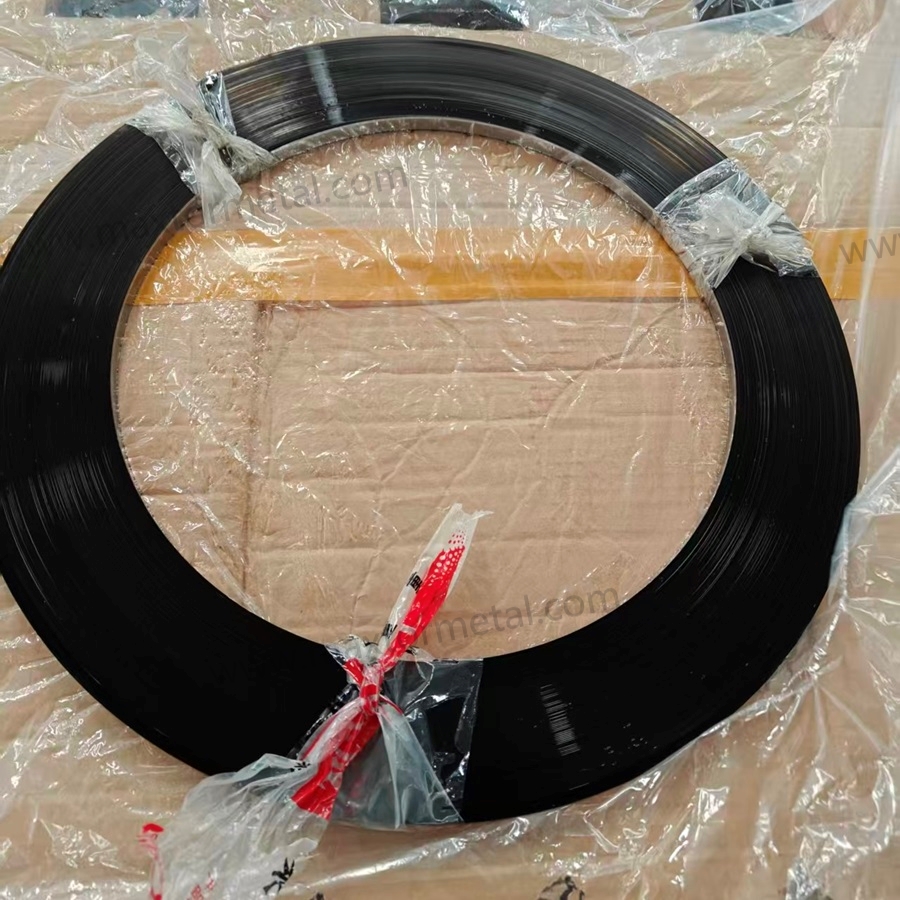
Risposta rapida: La riduzione della frequenza di cambio bobina migliora l'OEE principalmente riducendo i tempi di fermo pianificati, con un impatto diretto sulla Disponibilità. I guadagni secondari si registrano nelle Prestazioni (meno periodi di rampa dopo i riavvii) e nella Qualità (meno finestre di difetto legate alle giunzioni). L'effetto è quantificabile con quattro dati: tasso di consumo del nastro, lunghezza della bobina, tempo di cambio formato per ogni arresto e scarti generati per ogni cambio. In un esempio pratico con un consumo di 2.000 m/turno, il passaggio da bobine da 100 m a 500 m recupera oltre 3 ore di Disponibilità e circa $3.700 in valore di opportunità di produttività per turno.
Le linee di taglio e taglio longitudinale (slitting) alimentate a bobina di solito non perdono OEE perché qualcuno "si è dimenticato di andare veloce". Perdono OEE perché la linea è costretta a fermarsi — spesso ripetutamente — per cambi bobina, infilaggio del nastro e stabilizzazione.
If you’re trying to run longer, more stable production windows, the quickest lever is often to reduce coil change frequency. That’s why many teams start by auditing changeovers as an OEE Availability loss inside the OEE framework (OEE is typically calculated as Availability × Performance × Quality, as defined in ISO 22400-2:2021 — KPI definitions for manufacturing operations management.
In practice, coil length and consistency matter as much as changeover technique. If your strip supply is stable enough to support longer runs, you can often plan fewer interruptions per shift while still maintaining tight dimensional control.
Nota tecnica: If your coil supply spec needs to align with blade strip qualification requirements—including coil length, dimensional tolerance, and heat-treatment traceability—see Maxtor Metal’s reference page on industrial blade strip steel in beveled reels for form-factor specifications and long-run consistency controls.
- Why reducing coil change frequency improves Availability, labor, and waste
- What this model covers: OEE math, labor, splice scrap, throughput value
- Inputs needed: meters/shift, minutes/change, scrap meters/change, crew, rates, speed, yield
- Quick guide: what you’ll input, what you’ll get, and when this model applies
Quick calculator inputs (copy/paste)
| Input | Symbol in formulas | Unit | Notes / where to get it |
|---|---|---|---|
| Strip consumption per shift | meters_per_shift | m/shift | From MES, coil usage log, or tally sheet |
| Coil length | meters_per_coil | m/coil | Supplier spec / incoming inspection |
| Changeover time (internal) | minutes_per_change | min/change | From video time study or downtime log |
| Crew size (effective) | crew_size | people | Use effective crew if work is parallelized |
| Scrap per change | scrap_m_per_change | m/change | Splice tail-out + threading scrap |
| Line speed (steady-state) | line_speed_m_per_min | m/min | Use stable running speed |
| Restart yield / first-pass yield | yield | 0–1 | Measure post-change window separately if needed |
| Contribution value (optional) | value_per_meter | $/m | Prefer contribution margin, not revenue |
Tip: If your line is not the bottleneck, convert “lost meters” to “lost available time” and value it using contribution margin per hour instead of $/m.
Come una minore frequenza di cambi bobina aumenta la disponibilità OEE — e perché il calcolo è più semplice di quanto pensi
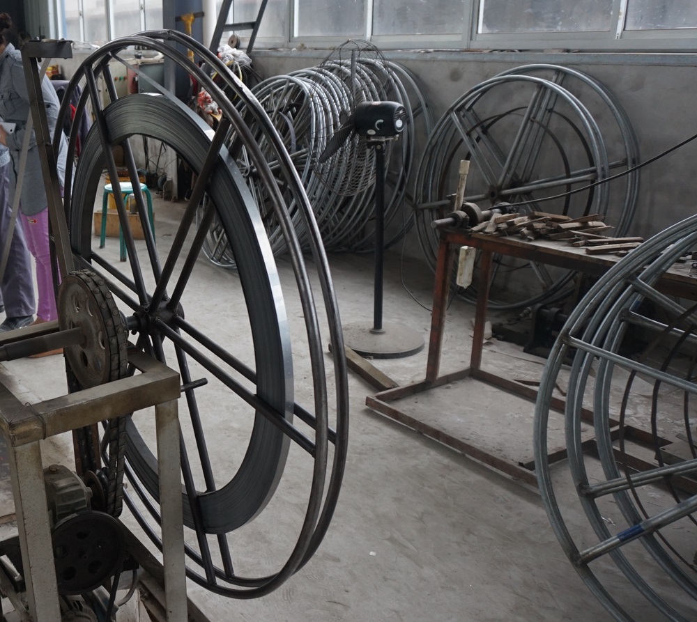
Availability, Performance, Quality linkages
Reducing coil changes primarily improves Disponibilità—often tracked as OEE Availability—because fewer changeovers means fewer planned stops inside scheduled production time.
It can also lift Prestazione E Qualità in small but real ways:
- Prestazione: fewer restarts means fewer ramp-up periods, fewer “micro-stops” while stabilizing tension, and less speed derating immediately after a splice.
- Qualità: each splice or threading event can create a small window of higher defect risk—mis-tracking, burr changes, edge waviness, or dimensional drift until tension and guide alignment settle.
Conclusione chiave: If you want a model that management accepts, keep the OEE logic clean: changeovers hit Availability directly. This article’s equations primarily quantify Availability losses and recovery from coil changes. Performance and Quality often improve too (fewer restarts, fewer defect windows), but those secondary gains are usually smaller and more site-specific—so measure them in a pilot using the same data dictionary and accounting rules before claiming total OEE uplift.
Downtime and labor equations
Use these as a practical starting point. Keep units consistent (minutes, meters, pieces).
Model boundaries (read before you use the formulas)
- “Lost meters” assumes the line is the constraint. The equation
lost_meters = downtime_min × line_speed × yieldonly reflects opportunity value if the line can actually convert recovered time into saleable output. - Separate internal vs external changeover work. If prep can happen while running (tools, next coil staging), treat it as external and do not count it in
minutes_per_changefor Availability. - Use an effective crew size. If only one operator is truly blocked during the stop while others continue value-added work, use
crew_size = 1(or a fraction). - Value per meter should be conservative. Prefer contribution margin (or opportunity value) rather than revenue, and document the assumption.
- Restart yield is not always the same as steady-state yield. If defects cluster after changes, measure the post-change window separately and use a lower
yieldfor that period.
- Change count per shift
changes_per_shift = meters_per_shift / meters_per_coil
(If you need an integer, round up—because partial coils still force a changeover.)
- Downtime per shift from coil changes
downtime_min = changes_per_shift × minutes_per_change
- Labor minutes per shift for changeovers
labor_min = downtime_min × crew_size
- Labor cost per shift (optional)
labor_cost = labor_min/60 × labor_rate_per_hour
This is intentionally simple: it counts the people tied up in the changeover window. If your crew is truly parallelized (one person changes coil while others keep value-added work going), reduce the effective crew size.
Splice scrap and lost throughput value
Two common “hidden” losses are easy to quantify.
- Splice / threading scrap
splice_scrap_m = changes_per_shift × scrap_m_per_change
If scrap is measured by weight instead of meters:
splice_scrap_kg = splice_scrap_m × kg_per_meter
- Lost throughput value from downtime
If your line has a stable selling value per meter (or a contribution margin per meter), you can estimate the value of time lost:
lost_meters = downtime_min × line_speed_m_per_min × yieldlost_value = lost_meters × value_per_meter
Where yield is the fraction of output that becomes saleable product in that operating window. If you don’t have a clean value-per-meter, substitute contribution margin per hour or a conservative “opportunity value” rate.
Confronto tra bobine da 100 m e 500 m (frequenza di cambio bobina)
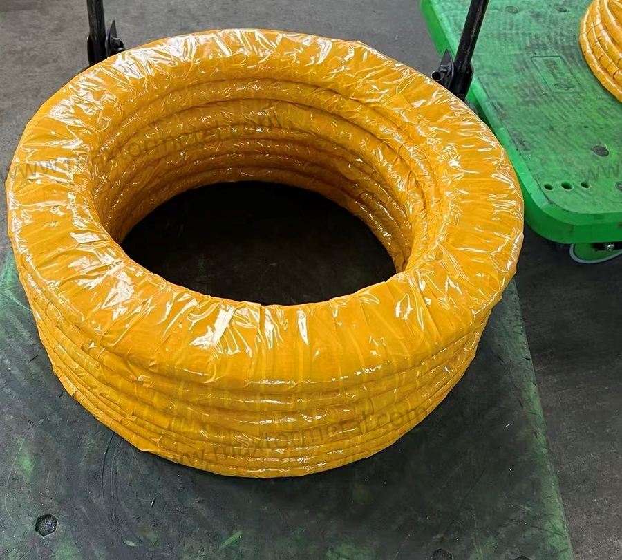
Assumptions and formula setup
This section shows how coil change frequency changes when you move from short coils to long coils, using the same line consumption rate.
The point of this comparison isn’t that 500 m is always better. The point is to expose the math so you can plug in your own plant data.
We’ll compare the impact of moving from 100 m coils to 500 m coils on:
- number of coil changes per shift
- changeover downtime
- changeover labor
- splice scrap
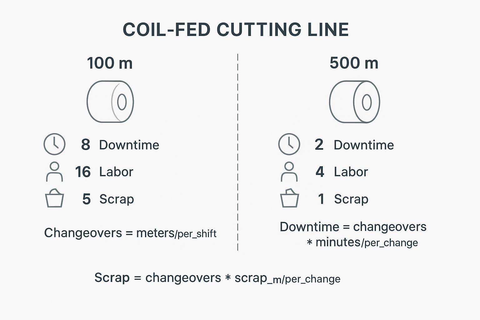
Worked example with conservative inputs
Assume a line consumes:
meters_per_shift = 2,000 mminutes_per_change = 12 minscrap_m_per_change = 3 mcrew_size = 2line_speed_m_per_min = 25 m/min(during steady running)yield = 0.98value_per_meter = $0.80(use contribution value, not revenue, if you can)
Case A: 100 m coils
changes_per_shift = 2,000 / 100 = 20downtime_min = 20 × 12 = 240 min(4.0 hours)labor_min = 240 × 2 = 480 min(8.0 labor-hours)splice_scrap_m = 20 × 3 = 60 mlost_meters = 240 × 25 × 0.98 = 5,880 mlost_value = 5,880 × $0.80 = $4,704 per shift
Case B: 500 m coils
changes_per_shift = 2,000 / 500 = 4downtime_min = 4 × 12 = 48 minlabor_min = 48 × 2 = 96 min(1.6 labor-hours)splice_scrap_m = 4 × 3 = 12 mlost_meters = 48 × 25 × 0.98 = 1,176 mlost_value = 1,176 × $0.80 = $940.80 per shift
Delta (100 m → 500 m)
- Changeovers: -16 per shift
- Tempo di inattività: -192 min per shift
- Labor time: -384 labor-min per shift (6.4 labor-hours)
- Splice scrap: -48 m per shift
- Throughput opportunity value: -$3,763 per shift (using the assumptions above)
These numbers look dramatic because the model assumes coil changes are true line stops and your line speed is meaningfully higher than “changeover pace.” If your line runs slower, or changeovers are partly externalized, the deltas shrink—but the direction usually stays the same.
Sensitivity levers and break-even notes
The economics of longer coils depend on a few levers you can sanity-check quickly:
- Minutes per change: If your changeover is 5 minutes instead of 12, the benefit is smaller—but still meaningful when changes are frequent.
- Meters per shift (consumption rate): Higher consumption makes coil length more valuable because you “burn through” small coils quickly.
- Scrap per change: Even modest splice scrap becomes significant when it happens 15–30 times per shift.
- Line speed during steady-state: Faster lines pay a higher opportunity cost for every stop.
- Yield during restart: If quality dips after a change (tracking, burr, surface marks, dimensional drift), your real value loss can exceed the simple downtime estimate.
A practical break-even check is to compare:
- added material/handling cost of longer coils (including storage, crane time, and any risk controls) versus
- recovered value from reduced downtime + reduced labor + reduced scrap.
Qué condiciones deben cumplirse para que las bobinas más largas realmente mejoren el OEE
Handling, tension, cores, and storage
Longer coils reduce changeovers, but they raise the bar for handling discipline E tension stability.
Key constraints to review before increasing coil length:
- Coil weight vs your crane and lifting fixtures (including sling angles and WLL)
- Mandrel and core spec compatibility (ID/OD, expansion range, core crush resistance)
- Brake capacity and unwind torque control (especially during acceleration/deceleration)
- Closed-loop tension control (dancer response, load-cell feedback, web/strip guide stability)
- Storage space, rack rating, and floor loading
When the strip steel itself is part of your stability problem (edge variation, thickness drift, residual stress), longer coils can amplify the pain: you’ll run longer before you realize the batch is unstable.
This is where supplier-side process control matters in a very practical way. When discussing coil length and quality control for blade strip supply, it’s reasonable to ask for evidence of heat treatment consistency E dimensional tolerances that hold over long, continuous runs—the same controls that determine whether a validated material grade like 440C will perform predictably across an extended coil. For a detailed framework on how those supplier-side controls are specified and verified for blade strip steel, see Validating 440C Dicer Replacement Blades at HRC 56–58. Maxtor Metal provides thickness tolerance records, periodic hardness sampling logs, and heat-treatment batch documentation formatted for audit-ready supplier review.
Safety, SOP, and training updates
Longer or heavier coils change the risk profile of a coil-fed line. Treat this as a controlled change: update standard work, re-train operators, and verify that handling limits and guarding assumptions still hold.
At a minimum, refresh (or add) the following:
- Training and competency: define who is qualified to run coil changes, who can operate lifting equipment, and what “sign-off” looks like after retraining.
- Lift plan and fixtures: approved fixtures only, WLL verification, exclusion zones, and clear hand signals/spotter rules.
- Lockout/tryout: isolate stored energy in brakes, pinch rolls, and tension systems before threading or clearing jams.
- Start-up recipe: documented tension/brake setpoints and a defined ramp-up sequence to reduce restart variability.
- First-meter validation: what to inspect right after restart (tracking, edge condition, burr changes, surface marks, and any dimensional checks).
For general material handling and storage guidance, see OSHA’s Materials Handling and Storage (OSHA 2236).
Use this as a lightweight standard-work checklist. Adjust to your machine’s guarding and interlock rules.
Before stop (external work)
- Next coil verified: ID/OD, core spec, edge protection intact
- Lifting plan confirmed: approved fixtures, WLL check, exclusion zone
- Tools and consumables staged: splice materials, knives, wrenches, gauges
- Correct unwind “recipe” ready: brake/torque setpoints, dancer/load-cell targets
During stop (internal work)
- Lockout/tryout per SOP for stored energy (brakes, pinch rolls, tension system)
- Coil head alignment and threading path verified (avoid twist and mis-tracking)
- Splice quality check: alignment, bonding, and tail-out management
After restart (first-meter verification)
- Tension stability: confirm dancer/load-cell response and steady tracking
- Edge/quality check: burr change, edge waviness, surface marks
- Dimensional check: width/thickness drift as applicable
- Record any ramp-up micro-stops and re-tune only via defined parameters (avoid “tribal” tweaks)
Any move to longer/heavier coils should trigger a short SOP refresh and competency check. For general handling and storage guidance, see OSHA’s “Materials Handling and Storage (OSHA 2236)” booklet: https://www.osha.gov/sites/default/files/publications/OSHA2236.pdf
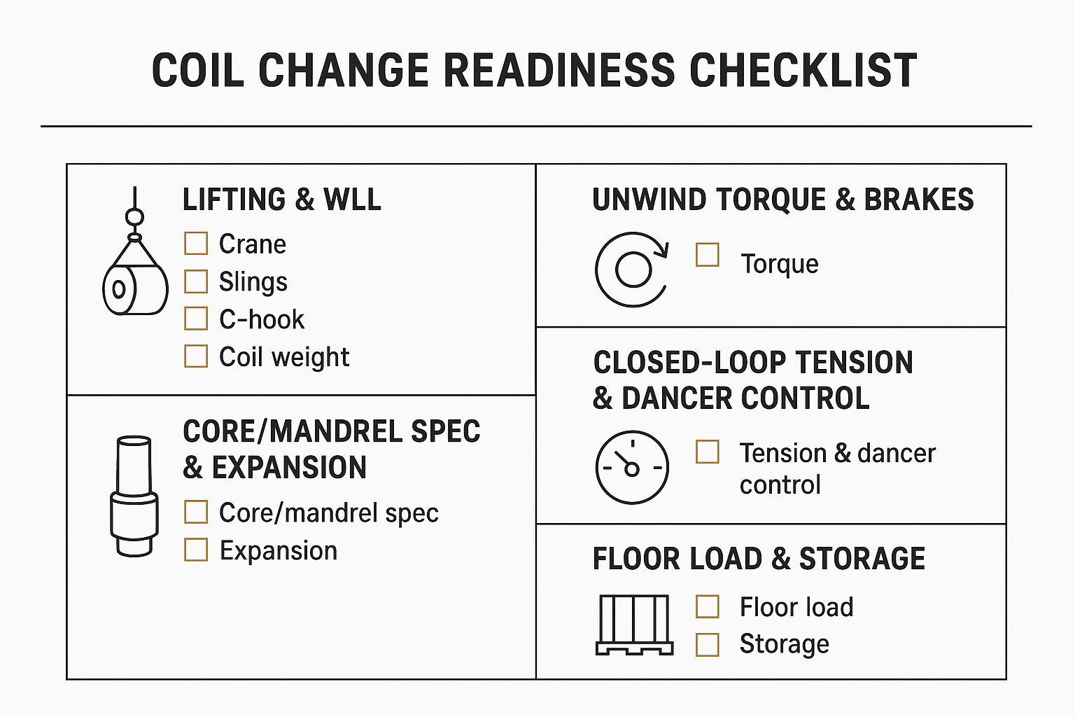
Update (or add) the following to standard work:
- Lifting plan: approved fixtures, WLL verification, exclusion zones, tag lines, and “hands-off” rules
- Lockout/tryout: isolate stored energy in brakes, pinch rolls, and tension systems before threading
- Threading method: defined path, guarding/interlocks, and safe hand positions
- Tension setpoints: start-up recipe and verification checks (what “stable” looks like)
- First-piece / first-meter validation: what to inspect after a change (tracking, edge condition, burr, surface)
Integration with auto-splicing and SMED
Reducing coil change frequency is one lever. Reducing the time and variability of the remaining changes is the other.
Two practical integrations:
- Auto-splicing (optional upgrade path): Auto-splicing can reduce the effective impact of coil changes by externalizing parts of the work and reducing restart variability. In many plants, it is a capital and integration decision (equipment capability, material compatibility, safety/guarding, and validation requirements), so it is not quantified in the simple equations above. Treat it as a next-step option after you baseline changeover time, scrap per change, and restart yield.
- SMED: The core SMED idea is to convert internal work (machine stopped) to external work (machine running), then standardize what remains. The method was developed by Shigeo Shingo and is documented in detail in A Revolution in Manufacturing: The SMED System. Productivity Press, 1985 (Primary source for SMED methodology.).
A simple SMED starter checklist for coil-fed lines:
- Pre-stage the next coil (ID verified, core verified, edge protected)
- Standardize threading tools and torque settings
- Use visual marks for alignment and strip path
- Parallelize the crew: one on mechanical change, one on verification and documentation
Caso pilota: Linea nastro in acciaio per lame 440C (anonimizzato)
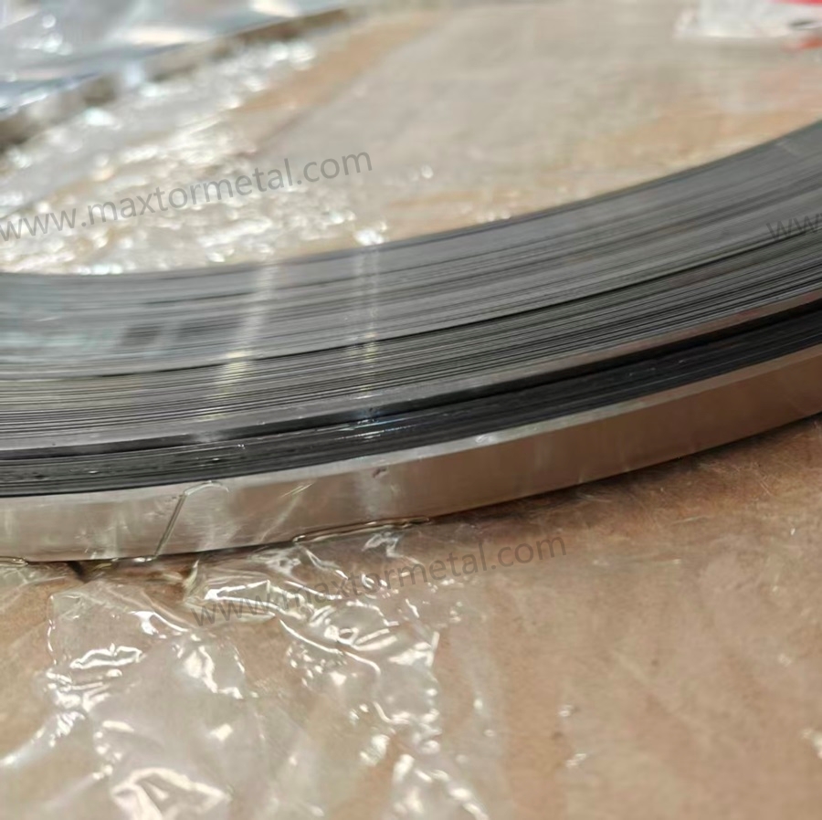
This anonymized case shows how a blade strip producer improved OEE by reducing coil change frequency while keeping product specs stable.
Project background
- Product: 440C blade strip steel, supplied to food-cutting blades and industrial band-knife makers
- Goal: reduce changeovers by increasing coil length (not by simply pushing rolling speed)
- Duration: ~5 settimane
- Proprietà e anonimizzazione dei dati: questo set di dati è stato raccolto dal team tecnico di Maxtor Metal durante un progetto congiunto di qualificazione del fornitore e ottimizzazione dei processi con il cliente. I dettagli identificativi del cliente sono stati anonimizzati previa autorizzazione.
Precondizioni (mantenute costanti)
- Stesso grado di acciaio, spessore, larghezza e processo di trattamento termico
- Stesso equipaggio/team; formazione standardizzata sul cambio attrezzaggio
- Nessuna nuova attrezzatura aggiunta (solo ottimizzazione del flusso di lavoro di processo e cambio attrezzaggio)
- Validazione della prima bobina eseguita a ogni turno
- Regole di calcolo dell'OEE invariate
Metodo di misurazione
Dizionario dei dati (significato di ciascuna metrica)
| Campo dati | Definizione (cosa registrare) | Unit | Fonte tipica |
|---|---|---|---|
| meters_per_shift | Nastro effettivo consumato durante il turno | m/shift | MES + registro di utilizzo delle bobine |
| minutes_per_change | Tempo dall'inizio del cambio attrezzaggio alla produzione stabile (escludere la preparazione esterna quando possibile) | min/change | Studio dei tempi video + registro dei tempi di inattività |
| scrap_m_per_change | Lunghezza dello scarto legata alla finestra di giunzione/infilaggio (scarto di coda + scarto di infilaggio) | m/change | Misurazione alla giunzione + registro degli scarti |
| cambi_per_turno | Numero di cambi bobina nel turno | conteggio/turno | Registro dell'operatore + registro dei tempi di inattività |
| fermo_pianificato_min | Somma dei minuti di arresto pianificato legati ai cambi bobina | min/turno | Registro dei tempi di inattività |
| delta_disponibilità | Variazione dei punti di Disponibilità rispetto alla baseline | punti | Report OEE (stesse regole di calcolo) |
| delta_oee | Variazione dei punti OEE complessivi rispetto alla baseline | punti | Report OEE (stesse regole di calcolo) |
Nota: in questo progetto pilota, per “produzione stabile” si intende il raggiungimento della normale finestra di funzionamento in cui la tensione, l'allineamento e i controlli di qualità hanno superato la validazione del primo metro del turno.
Per turno:
- registrare il consumo effettivo di nastro (m/turno)
- cronometrare ogni cambio attrezzaggio dall'inizio alla produzione stabile (min/cambio)
- misurare la lunghezza dello scarto intorno alla finestra di giunzione/infilaggio (m/cambio)
- contare i cambi per turno e sommare i tempi di inattività pianificati
- calcolare i delta di Disponibilità e dell'OEE complessivo
Linea di base (prima)
| Articolo | Linea di base |
|---|---|
| Coil length | 000–1.200 m/bobina |
| Consumo di nastro per lame | 600–3.100 m/turno |
| Cambi bobina | 2–3 / turno |
| Changeover time | 16–20 min/cambio |
| Scarto generato | 7–10 m/cambio |
L'analisi video ha suggerito ~60% del tempo di fermo non era dovuto alla sostituzione fisica della bobina in sé, ma a ritardi come la ricerca delle attrezzature di sollevamento, l'allineamento della testa della bobina, l'attesa di conferma e il ripristino della tensione: questo modello viene comunemente affrontato tramite l'analisi in stile SMED (separando il lavoro interno da quello esterno e standardizzando ciò che rimane).
Primo tentativo di miglioramento (solo lunghezza della bobina)
La lunghezza del coil è stata aumentata di circa il 30% (rispetto al valore di riferimento di 1.000–1.200 m a ~1.300–1.550 m) senza modifiche ai parametri di svolgimento o al flusso di lavoro di cambio. Il numero di cambi per turno è diminuito come previsto, ma il team ha registrato:
- Maggiore inerzia con OD più grande — la tensione di svolgimento ha oscillato di ±15–20% durante i primi 8–12 minuti dopo un cambio (rispetto a ±5% del valore di riferimento)
- Leggero serpeggiamento del nastro durante i primi ~20 minuti dopo un cambio, con conseguente necessità di intervento dell'operatore
- Lo scarto per cambio è aumentato dal valore di riferimento di 7–10 m a 11–15 m, compensando parzialmente la riduzione del numero di cambi
- Miglioramento della disponibilità netta: quasi nullo — meno arresti, ma finestre di riavvio più lunghe per ogni arresto
Il team ha respinto questo approccio e ha concluso che gli aumenti della lunghezza del coil devono essere associati a una ricalibrazione dei parametri di svolgimento e a procedure di cambio standardizzate. La lezione: la lunghezza del coil è una variabile di sistema, non una leva isolata.
Miglioramento finale (lunghezza del coil + processo + lavoro standardizzato)
Azioni intraprese:
- aumentata la lunghezza del coil di ~35–45%
- ricalibrati i parametri di svolgimento
- predisposti utensili e attrezzature
- standardizzato il posizionamento della testa del coil prima dell'arresto
- utilizzata una checklist per il cambio + verifica del riavvio
Risultati:
| Articolo | Prima | Dopo |
|---|---|---|
| Coil length | 000–1.200 m | 400–1.700 m |
| Consumo di nastro per lame | 600–3.100 m/turno | ~invariato |
| Changeover time | 16–20 min/cambio | 11–14 min/cambio |
| Scrap per change | 7–10 m | 4–6 m |
Riepilogo dei miglioramenti
| Metrico | Miglioramento |
|---|---|
| Cambi coil per turno | ↓ ~25–35% |
| Tempi di fermo pianificati | ↓ ~35–45% |
| Scarti di cambio formato | ↓ ~30–45% |
| Disponibilità | + ~2–4 punti |
| OEE complessivo | + ~3–6 punti |
Comportamenti degli operatori che hanno fatto la differenza
Le squadre ad alte prestazioni tipicamente:
- preparavano il coil successivo con circa 10 minuti di anticipo
- verificavano le attrezzature e il piano di sollevamento prima dell'arresto
- caricavano in anticipo la ricetta corretta della tensione di svolgimento
- eseguivano controlli immediati sul primo metro dopo il riavvio
Le squadre a prestazioni inferiori tendevano a:
- cercare gli utensili dopo l'arresto della linea
- ritardare i controlli sul primo coil
- affidarsi a una regolazione estemporanea della tensione
Anche a parità di attrezzatura, la differenza tra i turni era spesso di ~2–4 min/cambio.
Limiti di applicabilità
Questo approccio è più efficace quando:
- la produzione è stabile (stesso grado/specifica per lunghi cicli di produzione)
- gli aumenti di peso/OD del coil rientrano nei limiti di movimentazione
- il sistema di svolgimento è in grado di controllare in modo affidabile un'inerzia maggiore
Se la pianificazione prevede frequenti cambi di grado/larghezza/specifica, i vantaggi di coil più lunghi potrebbero essere vanificati dai cambi di SKU; pertanto, è consigliabile combinare la strategia della lunghezza del coil con lo SMED, la disciplina di pianificazione e il lavoro standardizzato, anziché affidarsi esclusivamente alla lunghezza del coil.

FAQ:
D: In che modo la frequenza di cambio bobina influisce sull'OEE?
Ogni cambio bobina è un arresto pianificato all'interno del tempo di produzione programmato, il che riduce direttamente la Disponibilità OEE. Crea inoltre una finestra di riavvio in cui le Prestazioni (rampa di velocità, stabilizzazione della tensione) e la Qualità (difetti adiacenti alla giunzione, deriva dimensionale) possono subire un calo. L'effetto combinato significa che la frequenza di cambio bobina è una delle leve OEE a rientro più rapido sulle linee alimentate a bobina, poiché accumula tre perdite recuperabili: tempi di fermo, manodopera e scarti di giunzione.
D: Qual è un obiettivo realistico per il tempo di cambio formato su una linea di nastri per lame alimentata a bobina?
In base ai dati pilota di questo articolo, un valore di riferimento di 16–20 min a cambio è comune prima dell'ottimizzazione in stile SMED. Dopo aver standardizzato il lavoro di preparazione esterna, pre-posizionato le attrezzature e verificato la ricetta di svolgimento prima dell'arresto, la stessa squadra ha raggiunto 11–14 min a cambio — una riduzione di circa il 25–35% — senza aggiungere macchinari. Le linee con capacità di giunzione automatica possono ridurre ulteriormente il tempo di cambio interno, ma il maggior guadagno singolo deriva in genere dalla conversione del tempo reattivo di "ricerca e selezione" in lavoro esterno pre-posizionato.
P: ¿Cómo calculo la pérdida de Disponibilidad del OEE debida a los cambios de bobina?
Utilizzare la formula: minuti_di_fermo = (metri_per_turno / metri_per_bobina) × minuti_per_cambio. Dividere il risultato per il tempo di produzione programmato per ottenere l'impatto sulla Disponibilità in percentuale. Ad esempio, 20 cambi/turno × 12 min/cambio = 240 min di fermo macchina pianificato. Su un turno de 8 ore (480 min), questo comporta una riduzione del 50% della Disponibilità dovuto ai soli cambi bobina — prima ancora di contare gli arresti non pianificati.
For grid-blade lines where slot-bottom fractures are a recurring unplanned-stop source, see Stopping Grid Blade Snapping at Slot Bottoms for the geometry and metallurgical controls that reduce snap-related line interruptions.
D: La lunghezza della bobina influisce sulla qualità del nastro o sulle prestazioni della lama?
La lunghezza della bobina in sé è neutra rispetto alla qualità del nastro; ciò che conta è se il controllo di processo del fornitore si mantiene costante su tutta la lunghezza della bobina. Bobine più lunghe amplificano qualsiasi deriva dimensionale o incostanza nel trattamento termico: si produce più a lungo prima di rilevare il problema. Questo è il motivo per cui l'aumento della lunghezza della bobina dovrebbe essere abbinato a una verifica della documentazione del fornitore, anziché essere trattato puramente come una decisione logistica. Nello specifico dell'acciaio in nastro per lame, la tolleranza dello spessore lungo la bobina e il campionamento periodico della durezza sono i due indicatori di controllo di processo più importanti da richiedere al fornitore.
D: Quando una bobina più lunga non migliora l'OEE?
Tre scenari comuni in cui il beneficio è limitato o negativo: (1) il programma di produzione cambia frequentemente tipo di materiale, larghezza o specifica — i cambi di SKU azzerano i guadagni derivanti da un minor numero di cambi bobina; (2) il sistema di svolgimento non riesce a controllare in modo affidabile la maggiore inerzia delle bobine con diametro esterno (OD) più grande, creando instabilità al riavvio che annulla i risparmi sui tempi di fermo; (3) la linea non rappresenta il vincolo — se le operazioni a valle fanno da collo di bottiglia, recuperare tempo di Disponibilità sulla linea della bobina non si traduce in un valore di produttività aggiuntivo.
D: Quale documentazione devo richiedere a un fornitore di acciaio in nastro per lame quando si passa a bobine più lunghe?
Come minimo: rapporti sulle tolleranze dimensionali (spessore e larghezza) campionati lungo l'intera lunghezza della bobina (non solo alle estremità), registri dei lotti di trattamento termico collegati ai numeri di lotto della bobina e registri di campionamento della durezza. Per le applicazioni di lame a contatto con gli alimenti, sono rilevanti anche i rapporti di passivazione e finitura superficiale (Ra ≤ 0,8 µm). Maxtor Metal fornisce questo pacchetto di documentazione — formattato per i programmi di audit dei fornitori — ai clienti che qualificano la fornitura di bobine per applicazioni di nastri per lame.
Per una guida passo-passo su come leggere e verificare questi documenti durante l'ispezione in entrata — inclusa la struttura del certificato EN 10204 3.1, il controllo incrociato della composizione chimica rispetto a ASTM A681/ISO 4957 e la mappatura della durezza a 9 punti — consultare la Lista di controllo MTC e QA per lame da taglio in acciaio per utensili..
Conclusione
- Vantaggi chiave: meno cambi formato, maggiore Disponibilità, minore manodopera per l'attrezzaggio, riduzione degli scarti di giunzione
- Passaggi successivi: inserire i dati dell'impianto, validare con un breve progetto pilota, verificare i limiti di movimentazione e sicurezza
Reducing coil change frequency is a clean OEE play because it attacks a visible loss bucket: planned downtime for changeovers. The ROI often survives conservative assumptions because you’re stacking three effects—Availability time back, fewer labor-minutes tied up in non-value-added work, and fewer splice-related scrap events.
If you want this to hold up in a technical review, treat coil length as a process capability question, not only a purchasing question. Longer stable runs require consistent heat treatment and tight dimensional control over the whole coil—which means your supplier’s QC documentation is part of the equation, not just the strip price.
Maxtor Metal supports customers running formal coil supply validation programs with batch-level documentation: dimensional tolerance records across coil length, heat-treatment consistency data, and hardness sampling logs formatted for audit-ready review. If your internal review requires a concrete long-coil supply spec as a reference point, the industrial blade strip steel in beveled reels product page is the relevant starting point.
Once coil change frequency is optimized, the next operational lever is blade lifecycle management. A structured regrind program — with measurable scrap/regrind thresholds and proactive sharpening intervals — can reduce annual knife consumable costs by 45–60%. See the Regrinding Industrial Strip Blades: Sharpening vs Scrap Guide for the full decision framework.
Riferimenti bibliografici
Note sulla trasparenza
- Last updated: 2026-07-11
- Nota informativa: This article includes a product example from Maxtor Metal for illustration. The OEE model and the pilot methodology can be applied with any qualified coil supplier.
- How the pilot data was measured: The pilot section summarizes an anonymized 5-week field trial with consistent OEE accounting rules, per-change time studies, and measured scrap length around the splice/threading window. In this context, changeover time means from changeover start to stable production (exclude external prep where possible), and scrap per change means tail-out + threading scrap measured around the splice/threading window.
- Nota sulla sicurezza: Always follow your site’s safety procedures, lifting plans, and equipment OEM instructions when changing coils or tuning tension systems.
- ISO. ISO 22400-2:2021 — Automation systems and integration — Key performance indicators (KPIs) for manufacturing operations management — Part 2: Definitions and descriptions. https://www.iso.org/standard/54497.html
- Shingo, S. A Revolution in Manufacturing: The SMED System. Productivity Press, 1985. (Primary source for SMED methodology.) https://books.google.com.pe/books?id=ooXVVIfqEQwC&printsec=frontcover
- OSHA. “Materials Handling and Storage (OSHA 2236).” https://www.osha.gov/sites/default/files/publications/OSHA2236.pdf
- OSHA. “OSHA procedures for safe weight limits when manually lifting (Standard Interpretations).” https://www.osha.gov/laws-regs/standardinterpretations/2013-06-04-0
- ASME. ASME B30.20 — Below-the-Hook Lifting Devices. American Society of Mechanical Engineers. https://www.asme.org/codes-standards/find-codes-standards/b30-20-hook-lifting-devices
Tommy Tang is a Senior Sales Engineer at Maxtor Metal with 12 years of experience supporting industrial customers with custom blade and blade strip supply, including coil-fed cutting and slitting applications. He holds CSE, Formazione continua in medicina (CME), Certificazione Six Sigma Green Belt, E PMP credentials, and focuses on helping engineers and technical buyers reduce downtime risk through material selection, dimensional consistency, and audit-friendly quality control.

 English
  Spanish
  Italian
  French
  Portuguese
  Russian
  German
  Arabic
  Hindi
Hindi  Vietnamese
  Indonesian
  Japanese
  Korean