

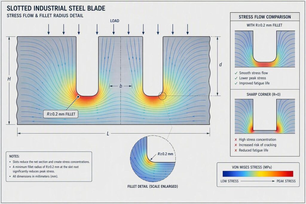
Risposta rapida: La rottura delle lame a griglia sul fondo cava è causata dalla coesistenza di tre fattori: elevata concentrazione degli sforzi elastici (Kt 7–12 per cave a spigolo vivo), difetti superficiali che agiscono come inneschi di cricca (strato di recast da EDM, bruciature di rettifica) e una tenacità insufficiente del materiale sottostante. La principale soluzione ingegneristica consiste nello specificare un raggio di raccordo del fondo cava R≥0,2 mm —che riduce il Kt di circa la metà rispetto a una geometria di R0,05 mm— abbinato alla completa rimozione dello strato di recast EDM tramite passate di finitura (skim cuts) e lucidatura, oltre a un trattamento termico di doppio rinvenimento calibrato sul grado di acciaio specifico. In un caso documentato su lame a griglia per cubettatrici a HRC 56–58, il controllo del raggio sul fondo cava a R0,20 mm ha ridotto le sostituzioni di emergenza delle lame di circa il 55–65% e i tempi di fermo macchina non pianificati di circa il 45–55%.
La rottura delle lame a griglia è una delle modalità di guasto più destabilizzanti e ingannevolmente incomprese nelle operazioni di taglio longitudinale (slitting) e taglio a griglia ad alta velocità. Quando una lama si frattura sul fondo cava, il risultato è immediato: fermi macchina non pianificati, perdita di resa al primo passaggio (FPY) e una serie di problemi secondari di qualità sul nastro. Per i responsabili di produzione e i capimpianto che gestiscono linee continue di lavorazione del nastro, un singolo evento di rottura può assorbire ore di manutenzione correttiva e generare scarti che erodono i margini mensili.
La causa principale è quasi sempre una concentrazione degli sforzi insita nella progettazione —o un difetto di processo mai rilevato—. Nelle lame con cave, il fondo cava rappresenta il punto di massimo sforzo dell'intero corpo utensile. In mancanza di un adeguato controllo geometrico e di un'idonea tenacità metallurgica, l'innesco della frattura è solo una questione di tempo.
La soluzione è una duplice strategia ingegneristica. In primo luogo, specificare e verificare un raggio di raccordo della cava R≥0,2 mm per ridurre in modo misurabile il fattore di concentrazione degli sforzi elastici (Kt) sul fondo cava. In secondo luogo, applicare un trattamento termico di doppio rinvenimento accuratamente calibrato per massimizzare la tenacità del materiale attorno a tale raccordo. A supporto di entrambe le strategie vi sono tre discipline di processo spesso trascurate nell'acquisto di utensili: la completa rimozione dello strato di recast EDM, il rigoroso evitamento delle bruciature di rettifica e il distensione delle tensioni residue prima dell'ispezione finale.
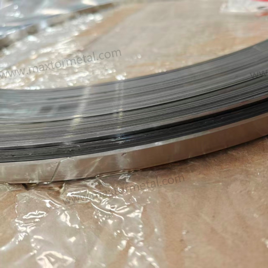
Nota tecnica: If your specification for slotted grid blades requires documented fillet radius verification, EDM process records, and heat-treat batch traceability, see Maxtor Metal’s reference page on industrial blade strip steel in beveled reels for supply specifications and documentation standards applicable to precision slotted blade geometries.
Questo articolo esamina in sequenza ogni elemento di tale duplice strategia: la meccanica che causa la frattura sul fondo cava, come la geometria del raccordo riduce in modo quantificabile il fattore Kt, quali controlli di integrità dell'elettroerosione (EDM) e della rettifica sono richiesti, come vengono selezionati i parametri di rinvenimento in base al grado di acciaio e quali punti di controllo di verifica chiudono il ciclo prima che la lama entri in servizio.
Perché il fondo cava è sempre il primo punto in cui si rompe una lama a griglia
Stress Concentration at Slot Bottoms
In a slotted blade under bending or cyclic cutting loads, stress is not distributed uniformly across the cross-section. It concentrates sharply at geometric discontinuities — and no feature on a slotted blade creates a sharper discontinuity than a tight slot root.
The theoretical stress concentration factor Kt relates the peak local stress σ max to the nominal applied stress σ nom:
Kt = σ max / σ nom
For a rectangular slot in a finite plate, Kt is strongly influenced by the ratio of the root radius R to the slot half-width B (or depth T, depending on the reference model). When R approaches zero — as it does with a square-cornered slot — Kt climbs toward singularity. Even at R = 0.05 mm, Kt values of 8–12 are common in tight-slot geometries at industrial blade scales. At those multipliers, a nominal bending stress of 300 MPa becomes a local stress exceeding 2,400 MPa — well above the fracture toughness threshold for most high-carbon tool steels in the hardened-and-lightly-tempered condition.
The slot bottom is therefore not just a stress concentration — it is the single most failure-critical feature in the tool design. Every process decision downstream of design — EDM strategy, grinding pass depth, tempering protocol, final inspection — must be evaluated in the context of what it does to that slot root.
Crack Initiation Sources in Slots
Even with adequate fillet geometry, cracks can initiate at slot bottoms when surface or subsurface defects provide nucleation sites. The three most consequential defect sources in slotted blade manufacture are:
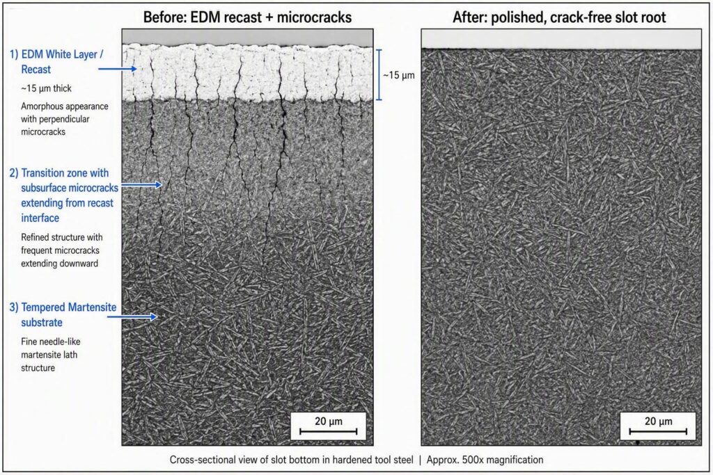
1. EDM recast (white) layer. Wire-EDM and sinker-EDM are standard processes for producing slots in hardened or semi-hardened tool steel. Both leave a resolidified, amorphous surface layer typically 2–25 µm thick. This layer is harder and more brittle than the base matrix — Vickers hardness values above 1,100 HV are common — and it contains tensile residual stresses and microcracks from the rapid resolidification thermal cycle. These microcracks are structural initiators under cyclic load. If left in place, they can propagate into the substrate within the first few thousand blade strokes.
2. Grinding-induced microcracks. Aggressive grinding after EDM — particularly with insufficient coolant delivery or excessive wheel speed — generates localized heat that causes surface temper, re-hardening, or micro-cracking. In the slot root geometry, where wheel access is restricted, coolant starvation is a persistent process risk.
3. Quench-induced residual tensile stress. During hardening, differential thermal contraction between the blade surface and core — particularly in the thin-wall regions around slots — generates residual tensile stresses. Without adequate stress-relief tempering, these stresses add directly to applied service stresses, reducing the effective fracture margin.
Role of Residual Tensile Stress
Residual stress is invisible to the inspector who uses only a hardness tester and a visual check. But it is fully additive to applied stress in the fracture-mechanics sense. A slot bottom carrying 150 MPa of residual tensile stress from quench shrinkage, combined with a 300 MPa applied bending stress and a Kt of 6, experiences a local stress state of approximately:
σ local ≈ Kt × (σ applied + σ residual) = 6 × 450 MPa = 2,700 MPa
Most high-alloy tool steels in service condition have plane-strain fracture toughness (KIC) between 20 and 35 MPa·m⁰·⁵ — but the range is wide because it spans different grades and heat-treat states.
For reference: D2 (1.2379) at HRC 58–62 typically shows KIC of 18–22 MPa·m⁰·⁵; M2 (1.3343) at HRC 62–65 is typically 20–25 MPa·m⁰·⁵; H13 (1.2344) at HRC 44–50 (lower hardness, higher toughness application) can reach 28–38 MPa·m⁰·⁵. When selecting a blade grade for a slotted geometry application, the KIC value at the intended service hardness — not an average range — is the relevant design input.
Progettazione del raggio di raccordo (Raggio di fondo cava)
Why R≥0.2 mm Reduces Kt
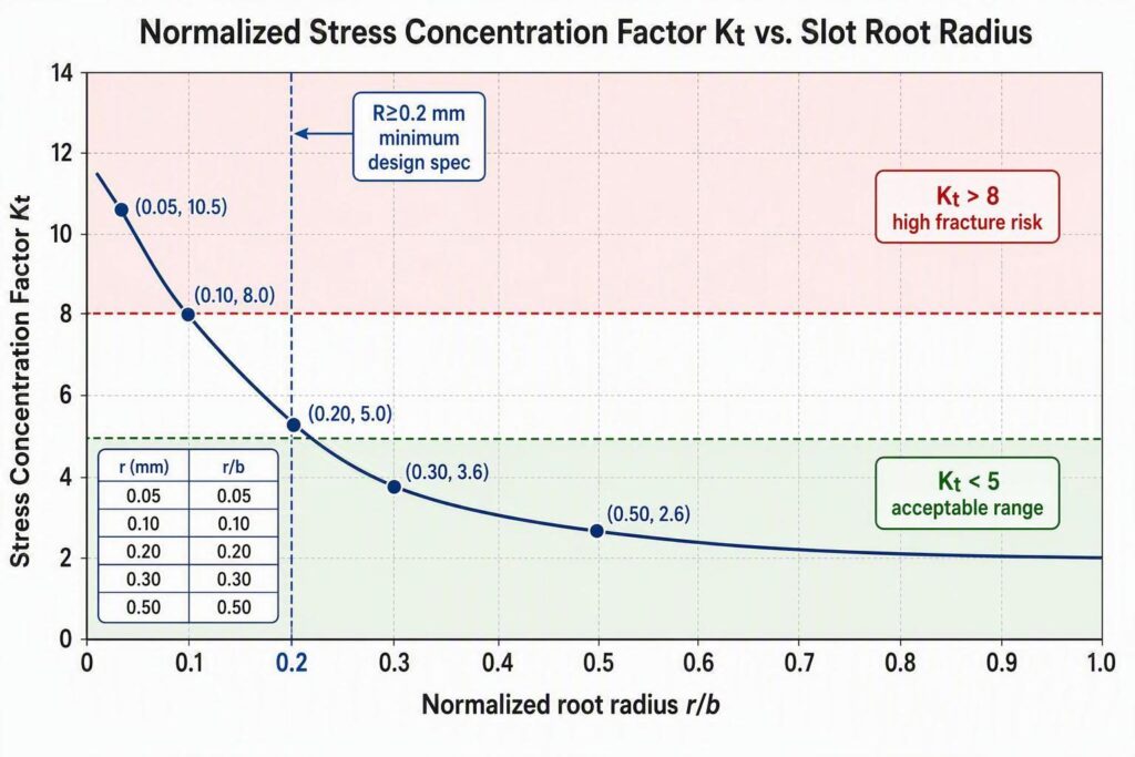
The relationship between fillet radius and Kt is nonlinear: the benefit is largest in the lower radius range, meaning the transition from R0.05 mm to R0.2 mm delivers a larger Kt reduction than the transition from R0.5 mm to R1.0 mm.
Using normalized stress concentration charts from Pilkey & Pilkey, Peterson’s Stress Concentration Factors (3rd ed., Wiley, 2008) for a slot in a finite-width plate under in-plane loading:
| Slot Root Radius r (mm) | Approximate Kt (typical slot geometry) |
|---|---|
| 0.05 | 10–12 |
| 0.10 | 7–8 |
| 0.20 | 4.5–5.5 |
| 0.30 | 3.5–4.0 |
| 0.50 | 2.5–3.0 |
The move from R0.05 mm to R0.20 mm cuts Kt roughly in half. If the material’s fracture resistance is held constant, halving Kt more than doubles the load-carrying capacity before crack initiation. Alternatively, at equivalent loads, halving Kt can extend fatigue life by an order of magnitude or more, depending on the fatigue crack growth exponent for the specific steel grade.
R0.2 mm is therefore a practical engineering minimum, not an arbitrary specification. It is the radius below which Kt rises sharply enough that even modest process variation — residual stress, surface defects, minor EDM recast remnants — pushes the slot bottom into reliable fracture territory.
Selecting Radius and Tolerances
Selecting the target radius requires balancing three competing constraints:
- Stress concentration reduction — a larger R is always mechanically beneficial.
- Slot dimensional function — the slot must still guide the strip or lock the grid pattern correctly. A root that is too large can interfere with a mating feature or alter the spring rate of thin blade webs.
- Manufacturability — the radius must be achievable and measurable by the processes in use (EDM skim cut, grinding, polishing).
For most industrial grid blade geometries, a target of R0.20 ± 0.05 mm is achievable with wire-EDM skim cuts followed by stone polishing, and is tight enough to maintain slot function while achieving the required Kt reduction. In thicker blades with deeper slots, R0.30–0.50 mm may be practical and should be evaluated where slot function permits.
Specify the tolerance unilaterally on engineering drawings: the minimum radius is the structural requirement; the maximum is a fit/function constraint. A notation of R0.20 min / R0.30 max makes this explicit and avoids the common shop-floor ambiguity of “rounding out the corner” without a defined upper limit.
Measuring and Verifying Radii
Slot root radii in the R0.2–R0.5 mm range require instrument-grade measurement. Acceptable methods include:
- Optical profilometry (non-contact): Resolves radii to ±0.005 mm; suitable for 100% inspection of critical slots.
- Radius gauge / ball gauge comparison: Adequate for in-process go/no-go at ±0.05 mm tolerance; fast and low-cost for line use.
- Coordinate measuring machine (CMM) with small-radius probe: ±0.003 mm achievable; recommended for first-article and PPAP documentation.
- Scanning electron microscopy (SEM) cross-section: Used for root-cause failure investigation, not routine inspection.
All measurement data must be recorded against the slot ID and correlated to the heat-treat lot. Radius measurement is a first-article requirement on any new tool geometry and a periodic in-process check during production.
Integrità superficiale da EDM (Elettroerosione) e rettifica
EDM Recast Layer and Microcracks
Wire-EDM and sinker-EDM both produce a recast (white) layer that is metallurgically distinct from the underlying steel matrix. The recast layer:
- Is amorphous or fine-grained resolidified material with elevated carbon content.
- Has Vickers hardness typically 950–1,200 HV — harder and more brittle than the tempered martensite below it.
- Contains tensile residual stresses up to 600–1,000 MPa in severe cases.
- Harbors shallow microcracks (depth 1–20 µm) oriented perpendicular to the machined surface.
These microcracks are structurally equivalent to pre-existing flaws in a fracture-mechanics model. At slot bottoms, where applied and residual stresses are already at maximum, even a 5 µm crack can be sufficient to initiate propagation at service loads. Leaving the recast layer in place at slot roots is a latent reliability defect — regardless of how tightly the fillet radius is held.
The thickness of the recast layer is controlled primarily by EDM energy parameters (peak current, pulse duration, open-circuit voltage) and dielectric flushing conditions. Rough-cut passes typically leave 15–25 µm; fine-cut passes leave 3–8 µm. The goal of a well-designed EDM strategy is to minimize recast thickness on the final pass and then remove what remains by mechanical means.
Skim Cuts and Post-EDM Polishing
The standard process for recast removal at slot bottoms is a two-stage approach:
Stage 1 — EDM skim cuts. After the rough-cut slot form is established, perform one or two additional EDM passes at reduced energy (lower peak current, longer pulse-off time). These skim cuts remove the recast layer from the previous pass, replacing it with a thinner layer typically below 3 µm. The fillet radius is refined in the final skim pass to approach the target R≥0.2 mm.
Stage 2 — Mechanical polishing. Post-EDM polishing at the slot root using fine-grit abrasive stones (600–1,200 grit) or flexible abrasive tools removes the residual skim-cut recast layer and introduces compressive surface stress. Polishing depth of 5–10 µm is typically sufficient. The polished surface should show tempered martensite structure under metallographic examination at 500×, with no visible white layer remaining.
Nital etch (2–4% nitric acid in ethanol) on a representative cross-section is the standard checkpoint: recast appears as an unetched white band, which must be absent at the slot root in production-released blades. For critical slots, the etch check should be performed on a first-article coupon machined from the same lot and EDM program as production blades.
Grinding Burn Detection and Control
Post-EDM grinding — whether to correct fillet form or to finish adjacent surfaces — carries a risk of thermal damage at the slot root. Grinding burn causes:
- Surface softening (over-tempering) in the most common low-heat case.
- Re-hardening (formation of untempered martensite) in severe heat cases.
- Reversal of residual stress to tensile, adding to the existing stress state.
- Micro-cracking in the re-hardened zone.
All of these conditions reduce fracture resistance. The slot bottom is especially vulnerable because coolant access is restricted by slot geometry, and high-alloy tool steel’s lower thermal diffusivity means heat dissipation into the bulk is slower than in carbide or HSS.
Grinding burn controls for slot operations include:
- Reduced depth of cut: ≤0.005 mm per pass for finishing passes near slot roots.
- Flood coolant delivery at the tool-work interface, not general-area flooding.
- Friable abrasive wheel grades (e.g., seeded-gel alumina) that release worn grains before heat buildup.
- Acoustic emission or spindle-power monitoring as real-time thermal load indicators.
Nital etch per ISO 14104 (surface temper etch inspection after grinding) is the industry-standard acceptance method for burn detection, applied on first-article and periodic production coupons. Barkhausen noise analysis provides a quantitative, non-destructive production gate for any lot that required post-EDM grinding near slot roots.
Rinvenimento termico per l'ottimizzazione della resilienza
Double Tempering Parameters by Steel Grade
High-carbon, high-chromium cold-work tool steels used in slotted grid blades — including D2 (equivalent to JIS G4404 SKD11, DIN EN ISO 4957 grade 1.2379, ASTM A681 Grade D2), H13, and ledeburitic grades such as M2 — require a structured double-temper protocol to achieve the toughness required at slot bottoms. Single-temper cycles are insufficient for two reasons: they do not fully decompose retained austenite, and they leave secondary martensite (formed from that retained austenite during cool-down) in an untempered, brittle state.
Double tempering protocol by grade:
| Grado di acciaio | First Temper | Soak Time | Second Temper | Soak Time | Target HRC |
|---|---|---|---|---|---|
| D2 / 1.2379 / SKD11 | 180–200 °C | 2 h | 180–200 °C | 2 h | 58–62 |
| M2 / 1.3343 | 540–560 °C | 2 h | 540–560 °C | 2 h | 62–65 |
| D3 / 1.2080 | 200–220 °C | 2 h | 200–220 °C | 2 h | 60–63 |
| 8% Cr steels (1.2379 mod.) | 190–210 °C | 2 h | 190–210 °C | 2 h | 59–62 |
The first temper tempers as-quenched martensite and drives partial decomposition of retained austenite into secondary martensite. The second temper then tempers that secondary martensite. Air cooling between tempers to below 50 °C is required to allow the retained-austenite transformation to complete before the second soak begins.
Temperature uniformity within the furnace load is critical: a ±5 °C gradient is the accepted maximum for tool steel tempering. Loads that exceed this produce hardness variation exceeding ±1 HRC within the lot — which translates directly to variation in slot-bottom fracture toughness.
Managing Retained Austenite and Cryo
For D2-type steels austenitized at the upper end of the recommended range (1,030–1,060 °C) to achieve higher dissolution of primary eutectic carbides (M₇C₃) and better wear resistance, retained austenite (RA) content after quench can reach 15–25 vol%. At these RA levels, double tempering alone may not reduce RA to the ≤5 vol% target for high-toughness applications at stress concentrations.
Cryogenic treatment — cooling to −75 °C (dry ice/solvent) or −196 °C (liquid nitrogen), inserted between quench and first temper — drives additional RA transformation before the martensite is tempered. The result is reduced RA (typically to <3 vol% after cryo + double temper), more homogeneous hardness, improved dimensional stability, and measurably better toughness at stress-concentrated features. Cryo is recommended for D2-type slotted blades austenitized above 1,040 °C when XRD measurements indicate >10 vol% RA after quench.
For a detailed framework on how retained austenite control — including XRD-based verification per ASTM E975 and the heat-treatment window for 440C-class blade strip steel — is specified and documented in a supplier qualification program, see Validating 440C Dicer Replacement Blades at HRC 56–58.
At Maxtor Metal, double-temper cycles are executed under SPC control with continuous furnace temperature data logging. Each production lot is charted against ±5 °C control limits for both soak temperature and time-at-temperature. Barkhausen noise screening is applied at the slot-root inspection zone as a post-temper release gate — catching any lot in which a temperature excursion or retained-austenite anomaly has shifted the subsurface stress state out of specification before that lot reaches assembly. This documented process architecture is what separates a blade built to engineering specification from one built to approximate practice.
Come verificare che la geometria della radice della cava e la metallurgia rientrino effettivamente nelle specifiche
Metallography and Nital Etch Checkpoints
Metallographic cross-sectioning at slot root locations is the ground-truth verification method. First-article and periodic production coupons are prepared as follows:
- Sectioning: Transverse cut through the slot root at mid-length.
- Mounting and polishing: Standard metallographic preparation to 0.05 µm alumina finish.
- Nital etch (2–4%): Reveals martensitic structure, recast white layer, grinding burn zones, and carbide distribution.
- Examination at 200×, 500×, 1,000×: Check for zero recast white layer at the slot root, tempered martensite morphology consistent with the target HRC range, uniform primary carbide distribution with no grain-boundary clustering, and no micro-cracks in the root zone.
Retained austenite quantification by X-ray diffraction (XRD) — per ASTM E975 — is performed on first-article and after any hardening process change. Production release target: ≤5 vol%.
For the incoming material verification side of this traceability chain — reading tool steel MTCs, verifying chemistry acceptance bands by grade, and linking heat numbers to coil tags — see Reading Tool Steel MTC for Strip Blades: A Practical QA Checklist.
Barkhausen and Dye Penetrant Screens
Barkhausen noise analysis (BNA) is a non-destructive magnetic method sensitive to near-surface residual stress and microstructure in ferromagnetic steels. At slot bottoms, BNA detects tensile residual stress elevation (reduced emission amplitude relative to a reference), grinding burn (altered martensite morphology shifts emission spectrum), and subsurface re-hardening zones not visible on the polished surface.
BNA probes are miniaturized to fit slot access geometry. Calibration is performed against a reference set of coupons with known residual stress states confirmed by XRD. Production accept/reject criteria are expressed as Barkhausen amplitude relative to a calibrated baseline: deviations >±15% trigger hold-and-investigate. SAE ARP4462 (Barkhausen Noise Inspection for Detecting Grinding Burns in High Strength Steel Parts) provides a recognized calibration and acceptance framework.
Dye penetrant inspection (DPI) — per ASTM E165 / ISO 3452 — is applied after final polishing and before coating or assembly. DPI is sensitive to surface-open cracks ≥1 µm in width and provides 100% production coverage where sectioning is destructive. Any indication in the slot root zone is cause for rejection.
PPAP-Style Documentation and Metrics
A PPAP-adapted control framework for tooling blades establishes the control plan, measurement system validation (MSA), and production metrics required to sustain slot-root quality:
| Document / Record | Content | Frequenza |
|---|---|---|
| First-article inspection report (FAIR) | CMM radius, hardness traverse, metallography, XRD RA, BNA baseline | Per new tool geometry |
| Control plan | Process parameters and in-process checks for EDM, grinding, tempering | Per blade family |
| SPC charts | Tempering temperature, fillet radius, hardness, BNA amplitude | Per production lot |
| Nital etch record | Photomicrograph archive of slot root cross-section, signed and dated | Per lot (coupon sample) |
| DPI log | Pass/fail per blade serial or lot | 100% production |
| Corrective action log | NCR linkage, root cause, and response action | Per rejection event |
SPC control limits for slot root radius are set at ±0.03 mm around nominal (e.g., 0.20–0.26 mm for an R0.23 mm nominal target). Process capability index Cpk ≥ 1.33 is the production release criterion. Lots falling below Cpk 1.33 on radius or hardness are placed on hold pending engineering review.
Caso cliente anonimizzato: Rottura della lama a griglia per cubettatrice sul fondo cava
The following case comes from a real dicer-blade failure investigation, shared anonymously with the customer’s consent. Identifying details — the processor’s identity, the machine brand, and the exact production line — are withheld at the customer’s request, and the before/after figures have been rounded and normalized to protect commercially sensitive production data. Even so, the mechanism, measurement sequence, and outcome all come from what actually happened on this line, and they show how the principles above play out when slot-root geometry is the dominant cause of grid blade snapping.
Production Scenario
An anonymous poultry processor on a high-throughput food-cutting line experienced repeated failures of its dicer grid/crosscut strip blades. The machine was a commercial rotary dicer of the ~3,000 kg/h class, processing frozen-tempered chicken for further food manufacturing. Typical machines in this class support poultry dicing across roughly 4.8–76 mm, depending on product thickness, feeding method, and machine condition.
This application ran at approximately:
- Product: frozen-tempered chicken
- Dice size: approximately 10–20 mm
- Blade material: Acciaio inossidabile 440C
- Target hardness: HRC 56–58
- Blade thickness: approximately 1.5–2.0 mm
- Production: multiple shifts per day
- Failure mode under investigation: grid blade snapping at the bottom of the locating slots
The critical detail is that the blade rarely failed because the cutting edge had worn out. The disruptive failure was a sudden fracture through the strip at a slot bottom — the same failure mode discussed throughout this article.
Original Blade Failure
The original grid blade used a relatively sharp slot-bottom transition, with nominal drawing geometry of approximately R0–0.10 mm. Because the broken blades appeared brittle, the maintenance team initially assumed a material or hardness problem.
During an initial failure review covering the documented fracture events recorded over the investigation period, approximately 70–85% of confirmed fractures were found to initiate in or immediately adjacent to the slot-bottom transition. (The exact sample count is withheld at the customer’s request; the percentage range reflects the bounds of the observed distribution across multiple documentation records.)
The typical sequence was:
- slot-bottom damage → small crack → cyclic crack growth → sudden blade fracture
The cutting edge itself could still appear serviceable immediately before failure. A dicer knife operates under repeated mechanical loading rather than a single static load, so a small geometric discontinuity readily becomes a fatigue initiation site — consistent with the general engineering guidance to use the largest practical fillet radius the functional geometry permits.
First Attempt: Reducing Hardness
Before touching geometry, the processor tried lowering the blade hardness from approximately HRC 58–60 to HRC 55–57, leaving the slot geometry unchanged.
The result reduced catastrophic snapping only slightly, while creating a new problem: edge wear increased, cut quality deteriorated earlier, sharpening/replacement frequency rose, and slot-bottom cracking was still observed. The attempt demonstrated an important principle — reducing hardness can change the failure response without eliminating the stress concentration that initiates the crack. The team therefore returned to the HRC 56–58 target and investigated the geometry.
Measurement Sequence
Step 1 — Map the fracture locations. Every failed grid blade was tagged by machine position, blade orientation, slot number, production hours, product condition, and fracture location. The purpose was to test whether fractures were random. They were not — the same slot-bottom geometry appeared repeatedly in the failure records.
Step 2 — Inspect the slot-bottom radius. Representative blades were checked with an optical comparator or toolmaker’s microscope. Measured radii were approximately R0.05–0.12 mm rather than a consistent larger radius, and some slot bottoms showed localized grinding marks. This matters because a drawing dimension alone does not describe the fatigue condition of a small radius: a nominal R0.10 mm radius with a grinding notch behaves differently from a smooth R0.10 mm radius.
Step 3 — Inspect the fracture origin. Broken blades were examined at low magnification for crack initiation location, grinding marks, local notches, impact evidence, deformation around the slot, and material defects. The recurring finding was that the fracture path tracked the slot-bottom transition rather than occurring randomly through the cutting edge — making a geometry change more logical than further hardness adjustment.
Geometry Modification
The trial retained 440C stainless steel at HRC 56–58. The primary design change was the slot-bottom radius:
- Slot-bottom radius: R0–0.10 mm → controlled R0.20 mm
The objective was not to make the radius “as large as possible” in isolation. The team used the largest radius that could be accommodated without interfering with blade engagement, adjacent components, grid spacing, product clearance, mounting geometry, or required dice dimensions. R0.20 mm should therefore be read as the design target for this application, not a universal dicer specification. The underlying rule is better stated as: use the largest practical slot-bottom radius that the blade geometry and machine clearance allow — consistent with the general principle that increasing a fillet radius reduces local stress concentration wherever geometry permits.
Grinding Process Control
The radius change alone was not considered sufficient. Grinding was standardized to avoid creating a new notch inside the radius. The inspection checklist included:
- Verify slot width
- Verify slot-bottom radius
- Check for visible grinding grooves
- Check for local undercutting
- Inspect the transition between slot wall and bottom
- Verify blade thickness
- Verify hardness on the qualification batch
- Inspect the first production run after installation
This reinforces a point made earlier: a nominal R0.20 mm radius is not automatically fatigue-resistant if the manufacturing process leaves a sharp grinding groove inside the radius.
For the regrind lifecycle framework that governs how many re-sharpenings a blade can sustain before slot-bottom geometry becomes a disqualifying factor, see Rettifica delle Lame Industriali a Nastro: Soglie di Affilatura, Criteri di Rottamazione e Modello di Costo del Ciclo di Vita.
Customer Case Results
Rounded, normalized figures from this customer’s production records:
| Metrico | Original design | R0.20 mm blades |
|---|---|---|
| Materiale | 440C | 440C |
| Durezza | HRC 56–58 | HRC 56–58 |
| Slot-bottom radius | R0–0.10 mm | R0.20 mm |
| Typical blade life | 70–100 h | 150–190 h |
| Premature snapping | Linea di base | ↓ approximately 55–65% |
| Emergency grid changes | Linea di base | ↓ approximately 50–60% |
| Tempo di inattività non pianificato | Linea di base | ↓ approximately 45–55% |
| Slot-bottom cracks during the trial period | Recurrent | None observed |
The most important observation was not the increase in average life — it was the change in failure mode. Before the modification, the maintenance team frequently had to respond to an unexpected broken grid blade. Afterward, routine wear and planned replacement became more significant than sudden slot-bottom fracture.
If your failure log shows that emergency grid-blade changes — rather than scheduled replacements — are the primary contributor to line downtime, the OEE model in OEE and Profit Gains from Reducing Coil Change Frequency provides a quantified framework for converting unplanned downtime reduction into a measurable OEE gain.
Example Downtime Calculation
At the customer’s baseline, the line logged approximately 6 emergency grid-blade failures per 1,000 operating hours, each requiring roughly 20–30 minutes of unplanned intervention. Using the 25-minute midpoint:
- 6 × 25 min = 150 min / 1,000 h
With emergency events down by approximately 55% after the change:
- 6 × (1 − 0.55) ≈ 2.7 events → 2.7 × 25 min ≈ 68 min / 1,000 h
The resulting saving was roughly 82 minutes of unplanned downtime per 1,000 operating hours. This is a normalized projection from the customer’s own baseline and post-change records; individual lines will vary with product mix and operating discipline.
Operator Behavior
The investigation also surfaced a human factor. In the early stage, operators sometimes kept running the machine after noticing an unusual sound or a small crack during inspection, risking a small fatigue crack growing into a complete break. The revised procedure introduced a simple rule: any visible crack at the slot bottom = remove and quarantine the blade. Operators were also instructed to inspect slot bottoms, blade seating, abnormal contact marks, product buildup, and evidence of impact. This is another reason the improvement should not be attributed to the R0.20 mm radius alone.
Process Limitations
The result should be interpreted within its operating window. It is most applicable to 440C dicer grid/crosscut strip blades at HRC 56–58, cutting frozen-tempered poultry, with controlled blade installation, normal production loading, and no significant metal contamination or abnormal impact. It should not be read as evidence that R0.20 mm is optimal for every dicer blade. A different blade thickness, slot width, dice size, material, heat treatment, machine, product temperature, or mounting method could require a different radius — cutting capacity and results depend on product condition, feeding method, machine condition, and knife configuration.
Case Conclusion
This anonymized frozen-tempered poultry dicing investigation identified repeated grid-blade fractures at the bottom of locating slots. The original slot geometry used a relatively sharp R0–0.10 mm transition, and replacement blades were made from 440C stainless steel at approximately HRC 56–58. An initial attempt to reduce hardness did not eliminate the problem and increased edge wear.
The subsequent work retained the HRC 56–58 material condition but increased the slot-bottom radius to a controlled R0.20 mm and tightened control of grinding damage and blade inspection. On this customer’s line, typical blade life increased from approximately 70–100 operating hours to 150–190 hours. Emergency grid-blade changes fell by approximately 50–60%, while unplanned downtime associated with blade snapping fell by approximately 45–55%. No slot-bottom cracks were observed during the follow-up period.
The result should not be interpreted as a universal “R0.20 mm doubles blade life” rule. The improvement came from controlling slot geometry together with grinding quality, blade hardness, installation, and operator inspection. The practical design rule is to use the largest slot-bottom radius that the dicer geometry and clearance allow, while avoiding grinding notches or undercuts at the radius transition.
Domande Frequenti
Qual è il raggio di raccordo minimo della cava per prevenire la rottura delle lame a griglia?
R: R0,2 mm rappresenta il minimo ingegneristico pratico per la maggior parte delle geometrie di lame industriali con cave. Al di sotto di questo valore, il fattore di concentrazione degli sforzi Kt aumenta drasticamente —fino a valori compresi tra 7 e 12— e, in combinazione con le tipiche variazioni di processo nelle tensioni residue e nella finitura superficiale, crea sistematicamente le condizioni per l'innesco di una frattura fragile sul fondo cava. Raggi maggiori (R0,3–0,5 mm) offrono un ulteriore margine di sicurezza e dovrebbero essere valutati ovunque la funzione della cava lo consenta.
D: Perché le lame intagliate si rompono sul fondo della cava anziché sul tagliente?
R: Il fondo della cava concentra uno sforzo elastico molte volte superiore allo sforzo nominale applicato in presenza di carichi ciclici e di flessione. Il tagliente, pur essendo soggetto a sforzo di contatto, beneficia durante il funzionamento di una geometria di contatto a compressione. La radice della cava è un concentratore geometrico di tensioni che accumula anche tensioni residue di trazione derivanti da elettroerosione (EDM) e tempra, rendendola il punto di innesco della frattura più probabile.
D: In che modo lo strato fuso da EDM causa cricche nelle lame in acciaio per utensili?
R: Lo strato di rifusione da EDM (strato bianco) è una struttura amorfa e risolidificata più dura della martensite di base —tipicamente 950–1.200 HV— che presenta tensioni residue di trazione e microcricche superficiali dovute al rapido ciclo di solidificazione. Dal punto di vista della meccanica della frattura, tali microcricche costituiscono difetti preesistenti. Sotto carico ciclico nella radice di una cava a elevata concentrazione di sforzi, esse si propagano nel substrato e possono innescare una frattura rapida già nelle prime ore di funzionamento se non rimosse prima della messa in servizio della lama.
D: Che cos'è il doppio rinvenimento e perché è necessario per le lame in acciaio per utensili con cave?
R: Il doppio rinvenimento prevede due cicli completi di rinvenimento (permanenza ad alta temperatura + raffreddamento in aria a temperatura ambiente + nuova permanenza). Il primo ciclo rinviene la martensite di tempra e decompone parzialmente l'austenite residua in martensite secondaria. Il secondo ciclo rinviene tale martensite secondaria. Un singolo rinvenimento lascia la martensite secondaria non rinvenuta e fragile: una carenza critica nei punti soggetti a concentrazione degli sforzi, come il fondo cava. Il doppio rinvenimento è una pratica standard prevista dalle specifiche ASTM A681 D2 e JIS G4404 SKD11 per utensili con cave ad elevata tenacità richiesta.
D: Come si individuano le bruciature di rettifica all'interno di una cava troppo stretta per le sonde standard?
R: L'analisi del rumore di Barkhausen (BNA) mediante sonde miniaturizzate adattate per l'accesso alle cave è il metodo non distruttivo più sensibile disponibile. La BNA rileva le variazioni superficiali nella struttura dei domini magnetici causate da danno termico, ritempra o tensioni residue di trazione — tutti segnali caratteristici delle bruciature di rettifica. L'attacco con Nital secondo ISO 14104 su sezioni metallografiche fornisce la conferma distruttiva sul primo pezzo e su campioni di produzione periodici.
D: Qual è il livello di austenite residua accettabile dopo la tempra delle lame intagliate in acciaio tipo D2?
R: Il target di rilascio per la produzione dopo tempra e doppio rinvenimento è ≤5% in volume di austenite residua, misurato tramite XRD secondo la norma ASTM E975. Gli acciai tipo D2 austenitizzati al di sopra dei 1.040 °C possono trattenere il 15–25% in volume dopo la tempra. Quando l'austenite residua supera il 10% in volume, si raccomanda un trattamento criogenico a −75 °C / −196 °C, inserito tra la tempra e il primo rinvenimento, per favorire un'ulteriore trasformazione prima dell'inizio del rinvenimento.
Quali controlli non distruttivi devono coprire le lame scanalate a griglia prima della spedizione?
Una sequenza completa di ispezione di produzione dovrebbe includere: analisi del rumore di Barkhausen sulle zone della radice della scanalatura per individuare bruciature da rettifica e anomalie di tensione residua; controllo con liquidi penetranti (DPI) secondo ASTM E165 / ISO 3452 per cricche affioranti in superficie; e verifica del raggio tramite profilometria ottica o CMM. Il test di durezza Rockwell C è un controllo di processo, non un sostituto dei metodi sopra indicati. Il DPI garantisce una copertura del 100% della lama; il BNA e i controlli del raggio rappresentano i principali criteri di qualità per l'integrità strutturala della radice della scanalatura.
Maxtor Metal fornisce ai clienti il pacchetto completo di documentazione NDT — inclusi i report di ampiezza BNA per zona di scanalatura, i registri superato/non superato DPI per matricola lama e i report di raggio CMM o profilometria — formattati per audit dei fornitori e verifiche in stile PPAP.
D: Come si impostano i limiti di controllo SPC per il raggio di raccordo della scanalatura in un programma di produzione lame?
R: Impostare il raggio nominale nel punto medio dell'intervallo di tolleranza funzionale. Definire i limiti di controllo e monitoraggio a ±0,03 mm attorno al valore nominale. Calcolare il Cpk dai dati di capacità del primo articolo (FAI) e richiedere un Cpk ≥ 1,33 come criterio di rilascio della produzione. Validare il sistema di misurazione (profilometria ottica o CMM) tramite uno studio Gauge R&R prima di avviare l'SPC per confermare che la variazione di misurazione non gonfi le stime di variazione del processo.
Conclusione
La rottura delle lame a griglia sul fondo della scanalatura non è una modalità di guasto casuale. È il risultato deterministico della coesistenza, nello stesso punto dell'utensile, di concentrazione degli sforzi, difetti superficiali e tenacia insufficiente.
Raccordi più ampi (R≥0,2 mm) riducono il fattore Kt di circa il 50% rispetto alle geometrie con angoli retti o stretti, abbattendo direttamente il picco di tensione sulla radice della scanalatura e prolungando la vita utile limitata da frattura. Il doppio rinvenimento — con parametri calibrati sulla specifica granatura dell'acciaio e sul contenuto di austenite residua — converte una microstruttura fragile da tempra in una matrice incrudita e tenace, in grado di assorbire l'energia di deformazione che altrimenti guiderebbe la propagazione delle cricche attraverso l'anima della lama.
Geometria e metallurgia da sole non sono sufficienti se non viene garantita l'integrità del processo. Gli strati di fusione residui (recast layer) lasciati dall'EDM devono essere rimossi meccanicamente nella sequenza di taglio di finitura (skim-cut) e lucidatura. Le operazioni di rettifica vicino alla radice della scanalatura devono essere rigorosamente controllate per prevenire bruciature e verificate tramite l'analisi del rumore di Barkhausen. Le tensioni residue devono essere gestite attraverso un adeguato controllo della velocità di tempra e un rinvenimento di distensione, senza essere ignorate confidando unicamente nella specifica di durezza.
L'elemento finale è la verifica sistematica: sezioni trasversali con attacco nital, screening BNA, controllo con liquidi penetranti e registrazioni di processo monitorate via SPC creano una catena di qualità documentata dalla specifica del raggio della scanalatura fino alla consegna. La standardizzazione di queste specifiche e controlli nell'ambito dell'intero programma di produzione lame trasforma l'affidabilità della lama da un risultato che si scopre durante l'uso in una caratteristica ingegnerizzata e verificata prima del primo utilizzo.
Maxtor Metal provides customers specifying precision slotted grid blades with batch-level documentation covering slot-root radius measurement records (CMM or optical profilometry), EDM skim-cut and nital etch verification, double-temper batch records with continuous furnace data logs, XRD-based retained austenite results, and Barkhausen noise screening reports at slot-root zones. Customers running formal supplier qualification programs can request the full documentation package before first shipment to validate that slot-root geometry and heat-treat parameters are controlled to engineering specification, not estimated from process experience.
Informazioni sull'autore
Jesse Xu — Ingegnere senior della qualità, QA (Controllo Qualità), Maxtor Metal
Jesse Xu is a Senior Quality Engineer with 15 years of experience in industrial blade manufacturing and quality assurance. His work focuses on failure analysis: determining whether blade failures such as edge chipping and premature wear originate from heat-treatment process deviations or from material segregation (carbide/banding) issues. He holds the ASQ Certified Quality Engineer (CQE) credential, is an ISO 9001 Lead Auditor, and is certified to ASNT NDT Level II.
Informativa e contatti
This article is published by Maxtor Metal, a manufacturer and supplier of custom, precision-ground industrial blades. It is provided for technical education and product explanation; because it references Maxtor Metal products, readers should be aware of a potential commercial interest. Technical claims are referenced to publicly available standards (ISO, ASTM, SAE) and established engineering literature, and readers are encouraged to verify specifications against their own application requirements.
For questions about this article, blade design specifications, or technical support, please reach out via our pagina dei contatti.

 English
  Spanish
  Italian
  French
  Portuguese
  Russian
  German
  Arabic
  Hindi
Hindi  Vietnamese
  Indonesian
  Japanese
  Korean