

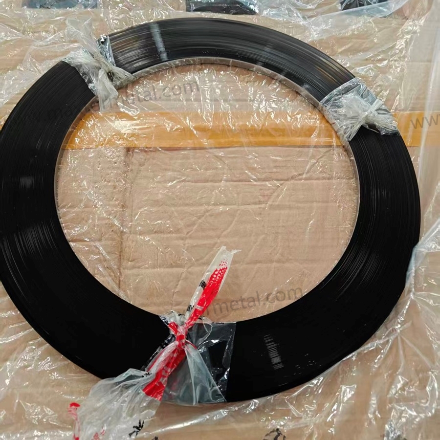
Resumen rápido: La reducción de la frecuencia de cambio de bobina mejora el OEE principalmente al recortar el tiempo de inactividad planificado, lo que impacta directamente en la Disponibilidad. Las ganancias secundarias se reflejan en el Rendimiento (menos períodos de aceleración tras los reinicios) y en la Calidad (menos ventanas de defectos asociadas a los empalmes). El efecto es cuantificable mediante cuatro variables: tasa de consumo de fleje, longitud de la bobina, tiempo de cambio por parada y desperdicio generado por cambio. En un ejemplo práctico con un consumo de 2,000 m por turno, pasar de bobinas de 100 m a 500 m recupera más de 3 horas de Disponibilidad y aproximadamente $3,700 en valor de oportunidad de rendimiento por turno.
Las líneas de corte y longitudinales (slitting) alimentadas por bobina generalmente no pierden OEE porque alguien "se olvidó de trabajar rápido". Pierden OEE porque la línea se ve obligada a detenerse, a menudo repetidamente, para los cambios de bobina, el enhebrado y la estabilización.
Si busca operar con ventanas de producción más largas y estables, la palanca más rápida suele ser reducir la frecuencia de cambio de bobinas. Por ello, muchos equipos comienzan auditando los cambios como una pérdida de Disponibilidad OEE dentro del marco de OEE (el OEE se calcula típicamente como Disponibilidad × Rendimiento × Calidad, según se define en ISO 22400-2:2021 — Definiciones de KPI para la gestión de operaciones de fabricación.
In practice, coil length and consistency matter as much as changeover technique. If your strip supply is stable enough to support longer runs, you can often plan fewer interruptions per shift while still maintaining tight dimensional control.
Nota de ingeniería: Si la especificación de suministro de su bobina debe alinearse con los requisitos de calificación del fleje de cuchilla (incluyendo la longitud de la bobina, la tolerancia dimensional y la trazabilidad del tratamiento térmico), consulte la página de referencia de Maxtor Metal sobre acero en fleje para cuchillas industriales en bobinas biseladas de Maxtor Metal para especificaciones de factor de forma y controles de consistencia a largo plazo.
- Por qué reducir la frecuencia de cambio de bobinas mejora la Disponibilidad, la mano de obra y los residuos
- Qué cubre este modelo: cálculo de OEE, mano de obra, merma por empalme, valor de rendimiento
- Datos de entrada necesarios: metros/turno, minutos/cambio, metros de merma/cambio, personal, tarifas, velocidad, rendimiento
- Guía rápida: qué ingresará, qué obtendrá y cuándo se aplica este modelo
Datos de entrada de la calculadora rápida (copiar/pegar)
| Aporte | Símbolo en las fórmulas | Unidad | Notas / dónde obtenerlo |
|---|---|---|---|
| Consumo de fleje por turno | metros_por_turno | m/turno | Desde el MES, registro de uso de bobinas o planilla de control |
| Longitud de la bobina | metros_por_bobina | m/bobina | Especificación del proveedor / inspección de recepción |
| Tiempo de cambio (interno) | minutos_por_cambio | min/cambio | A partir de un estudio de tiempos en video o registro de tiempos de inactividad |
| Tamaño del equipo de trabajo (efectivo) | tamaño_del_equipo | personas | Utilice el personal efectivo si el trabajo se realiza en paralelo |
| Merma por cambio | metros_de_desecho_por_cambio | m/cambio | Merma por cola de empalme + enhebrado |
| Velocidad de línea (estado estable) | velocidad_de_linea_m_por_min | m/min | Utilice la velocidad de funcionamiento estable |
| Rendimiento de reinicio / rendimiento de primer paso (first-pass yield) | rendimiento | 0–1 | Mida la ventana posterior al cambio por separado si es necesario |
| Valor de contribución (opcional) | valor_por_metro | $/m | Prefiera el margen de contribución, no los ingresos |
Consejo: Si su línea no es el cuello de botella, convierta los “metros perdidos” en “tiempo disponible perdido” y valórelo utilizando el margen de contribución por hora en lugar de $/m.
Cómo una menor frecuencia de cambios de bobina impulsa la disponibilidad de OEE, y por qué el cálculo es más simple de lo que piensa
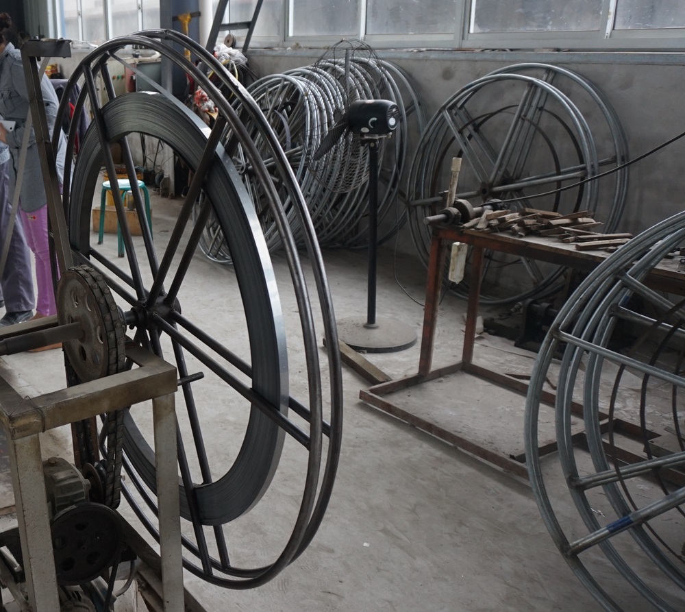
Vínculos entre Disponibilidad, Rendimiento y Calidad
Reducir los cambios de bobina mejora principalmente la Disponibilidad—often tracked as pérdida de Disponibilidad OEE—because fewer changeovers means fewer planned stops inside scheduled production time.
It can also lift Actuación y Calidad in small but real ways:
- Actuación: fewer restarts means fewer ramp-up periods, fewer “micro-stops” while stabilizing tension, and less speed derating immediately after a splice.
- Calidad: each splice or threading event can create a small window of higher defect risk—mis-tracking, burr changes, edge waviness, or dimensional drift until tension and guide alignment settle.
Conclusión clave: If you want a model that management accepts, keep the OEE logic clean: changeovers hit Availability directly. This article’s equations primarily quantify Availability losses and recovery from coil changes. Performance and Quality often improve too (fewer restarts, fewer defect windows), but those secondary gains are usually smaller and more site-specific—so measure them in a pilot using the same data dictionary and accounting rules before claiming total OEE uplift.
Downtime and labor equations
Use these as a practical starting point. Keep units consistent (minutes, meters, pieces).
Model boundaries (read before you use the formulas)
- “Lost meters” assumes the line is the constraint. The equation
lost_meters = downtime_min × line_speed × yieldonly reflects opportunity value if the line can actually convert recovered time into saleable output. - Separate internal vs external changeover work. If prep can happen while running (tools, next coil staging), treat it as external and do not count it in
minutos_por_cambiofor Availability. - Use an effective crew size. If only one operator is truly blocked during the stop while others continue value-added work, use
crew_size = 1(or a fraction). - Value per meter should be conservative. Prefer contribution margin (or opportunity value) rather than revenue, and document the assumption.
- Restart yield is not always the same as steady-state yield. If defects cluster after changes, measure the post-change window separately and use a lower
rendimientofor that period.
- Change count per shift
changes_per_shift = meters_per_shift / meters_per_coil
(If you need an integer, round up—because partial coils still force a changeover.)
- Downtime per shift from coil changes
downtime_min = changes_per_shift × minutes_per_change
- Labor minutes per shift for changeovers
labor_min = downtime_min × crew_size
- Labor cost per shift (optional)
labor_cost = labor_min/60 × labor_rate_per_hour
This is intentionally simple: it counts the people tied up in the changeover window. If your crew is truly parallelized (one person changes coil while others keep value-added work going), reduce the effective crew size.
Splice scrap and lost throughput value
Two common “hidden” losses are easy to quantify.
- Splice / threading scrap
splice_scrap_m = changes_per_shift × scrap_m_per_change
If scrap is measured by weight instead of meters:
splice_scrap_kg = splice_scrap_m × kg_per_meter
- Lost throughput value from downtime
If your line has a stable selling value per meter (or a contribution margin per meter), you can estimate the value of time lost:
lost_meters = downtime_min × line_speed_m_per_min × yieldlost_value = lost_meters × value_per_meter
Where rendimiento is the fraction of output that becomes saleable product in that operating window. If you don’t have a clean value-per-meter, substitute contribution margin per hour or a conservative “opportunity value” rate.
Comparativa de bobinas de 100 m vs 500 m (frecuencia de cambio de bobina)
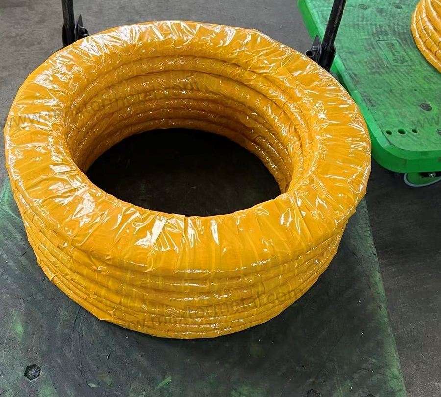
Assumptions and formula setup
This section shows how la frecuencia de cambio de bobinas changes when you move from short coils to long coils, using the same line consumption rate.
The point of this comparison isn’t that 500 m is always better. The point is to expose the math so you can plug in your own plant data.
We’ll compare the impact of moving from 100 m coils to 500 m coils on:
- number of coil changes per shift
- changeover downtime
- changeover labor
- splice scrap
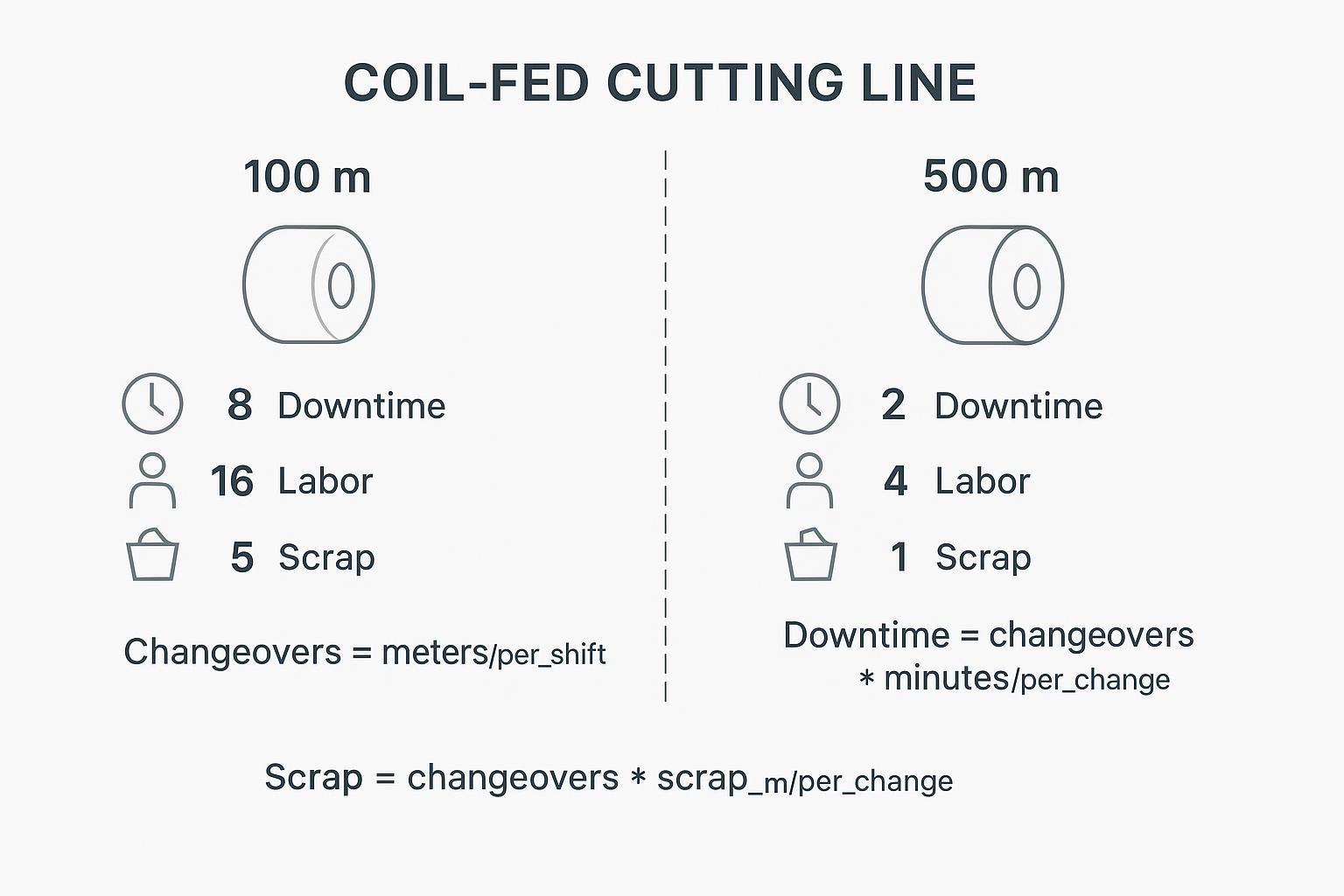
Worked example with conservative inputs
Assume a line consumes:
meters_per_shift = 2,000 mminutes_per_change = 12 minscrap_m_per_change = 3 mcrew_size = 2line_speed_m_per_min = 25 m/min(during steady running)yield = 0.98value_per_meter = $0.80(use contribution value, not revenue, if you can)
Case A: 100 m coils
changes_per_shift = 2,000 / 100 = 20downtime_min = 20 × 12 = 240 min(4.0 hours)labor_min = 240 × 2 = 480 min(8.0 labor-hours)splice_scrap_m = 20 × 3 = 60 mlost_meters = 240 × 25 × 0.98 = 5,880 mlost_value = 5,880 × $0.80 = $4,704 per shift
Case B: 500 m coils
changes_per_shift = 2,000 / 500 = 4downtime_min = 4 × 12 = 48 minlabor_min = 48 × 2 = 96 min(1.6 labor-hours)splice_scrap_m = 4 × 3 = 12 mlost_meters = 48 × 25 × 0.98 = 1,176 mlost_value = 1,176 × $0.80 = $940.80 per shift
Delta (100 m → 500 m)
- Changeovers: -16 per shift
- Falta del tiempo: -192 min per shift
- Labor time: -384 labor-min per shift (6.4 labor-hours)
- Splice scrap: -48 m per shift
- Throughput opportunity value: -$3,763 per shift (using the assumptions above)
These numbers look dramatic because the model assumes coil changes are true line stops and your line speed is meaningfully higher than “changeover pace.” If your line runs slower, or changeovers are partly externalized, the deltas shrink—but the direction usually stays the same.
Sensitivity levers and break-even notes
The economics of longer coils depend on a few levers you can sanity-check quickly:
- Minutes per change: If your changeover is 5 minutes instead of 12, the benefit is smaller—but still meaningful when changes are frequent.
- Meters per shift (consumption rate): Higher consumption makes coil length more valuable because you “burn through” small coils quickly.
- Merma por cambio: Even modest splice scrap becomes significant when it happens 15–30 times per shift.
- Line speed during steady-state: Faster lines pay a higher opportunity cost for every stop.
- Yield during restart: If quality dips after a change (tracking, burr, surface marks, dimensional drift), your real value loss can exceed the simple downtime estimate.
A practical break-even check is to compare:
- added material/handling cost of longer coils (including storage, crane time, and any risk controls) versus
- recovered value from reduced downtime + reduced labor + reduced scrap.
Qué condiciones deben cumplirse para que las bobinas más largas realmente mejoren el OEE
Handling, tension, cores, and storage
Longer coils reduce changeovers, but they raise the bar for handling discipline y tension stability.
Key constraints to review before increasing coil length:
- Coil weight vs your crane and lifting fixtures (including sling angles and WLL)
- Mandrel and core spec compatibility (ID/OD, expansion range, core crush resistance)
- Brake capacity and unwind torque control (especially during acceleration/deceleration)
- Closed-loop tension control (dancer response, load-cell feedback, web/strip guide stability)
- Storage space, rack rating, and floor loading
When the strip steel itself is part of your stability problem (edge variation, thickness drift, residual stress), longer coils can amplify the pain: you’ll run longer before you realize the batch is unstable.
This is where supplier-side process control matters in a very practical way. When discussing coil length and quality control for blade strip supply, it’s reasonable to ask for evidence of heat treatment consistency y dimensional tolerances that hold over long, continuous runs—the same controls that determine whether a validated material grade like 440C will perform predictably across an extended coil. For a detailed framework on how those supplier-side controls are specified and verified for blade strip steel, see Validación de cuchillas de repuesto para picadoras en 440C a HRC 56–58. Maxtor Metal provides thickness tolerance records, periodic hardness sampling logs, and heat-treatment batch documentation formatted for audit-ready supplier review.
Safety, SOP, and training updates
Longer or heavier coils change the risk profile of a coil-fed line. Treat this as a controlled change: update standard work, re-train operators, and verify that handling limits and guarding assumptions still hold.
At a minimum, refresh (or add) the following:
- Training and competency: define who is qualified to run coil changes, who can operate lifting equipment, and what “sign-off” looks like after retraining.
- Lift plan and fixtures: approved fixtures only, WLL verification, exclusion zones, and clear hand signals/spotter rules.
- Lockout/tryout: isolate stored energy in brakes, pinch rolls, and tension systems before threading or clearing jams.
- Start-up recipe: documented tension/brake setpoints and a defined ramp-up sequence to reduce restart variability.
- First-meter validation: what to inspect right after restart (tracking, edge condition, burr changes, surface marks, and any dimensional checks).
For general material handling and storage guidance, see OSHA’s Materials Handling and Storage (OSHA 2236).
Use this as a lightweight standard-work checklist. Adjust to your machine’s guarding and interlock rules.
Before stop (external work)
- Next coil verified: ID/OD, core spec, edge protection intact
- Lifting plan confirmed: approved fixtures, WLL check, exclusion zone
- Tools and consumables staged: splice materials, knives, wrenches, gauges
- Correct unwind “recipe” ready: brake/torque setpoints, dancer/load-cell targets
During stop (internal work)
- Lockout/tryout per SOP for stored energy (brakes, pinch rolls, tension system)
- Coil head alignment and threading path verified (avoid twist and mis-tracking)
- Splice quality check: alignment, bonding, and tail-out management
After restart (first-meter verification)
- Tension stability: confirm dancer/load-cell response and steady tracking
- Edge/quality check: burr change, edge waviness, surface marks
- Dimensional check: width/thickness drift as applicable
- Record any ramp-up micro-stops and re-tune only via defined parameters (avoid “tribal” tweaks)
Any move to longer/heavier coils should trigger a short SOP refresh and competency check. For general handling and storage guidance, see OSHA’s “Materials Handling and Storage (OSHA 2236)” booklet: https://www.osha.gov/sites/default/files/publications/OSHA2236.pdf
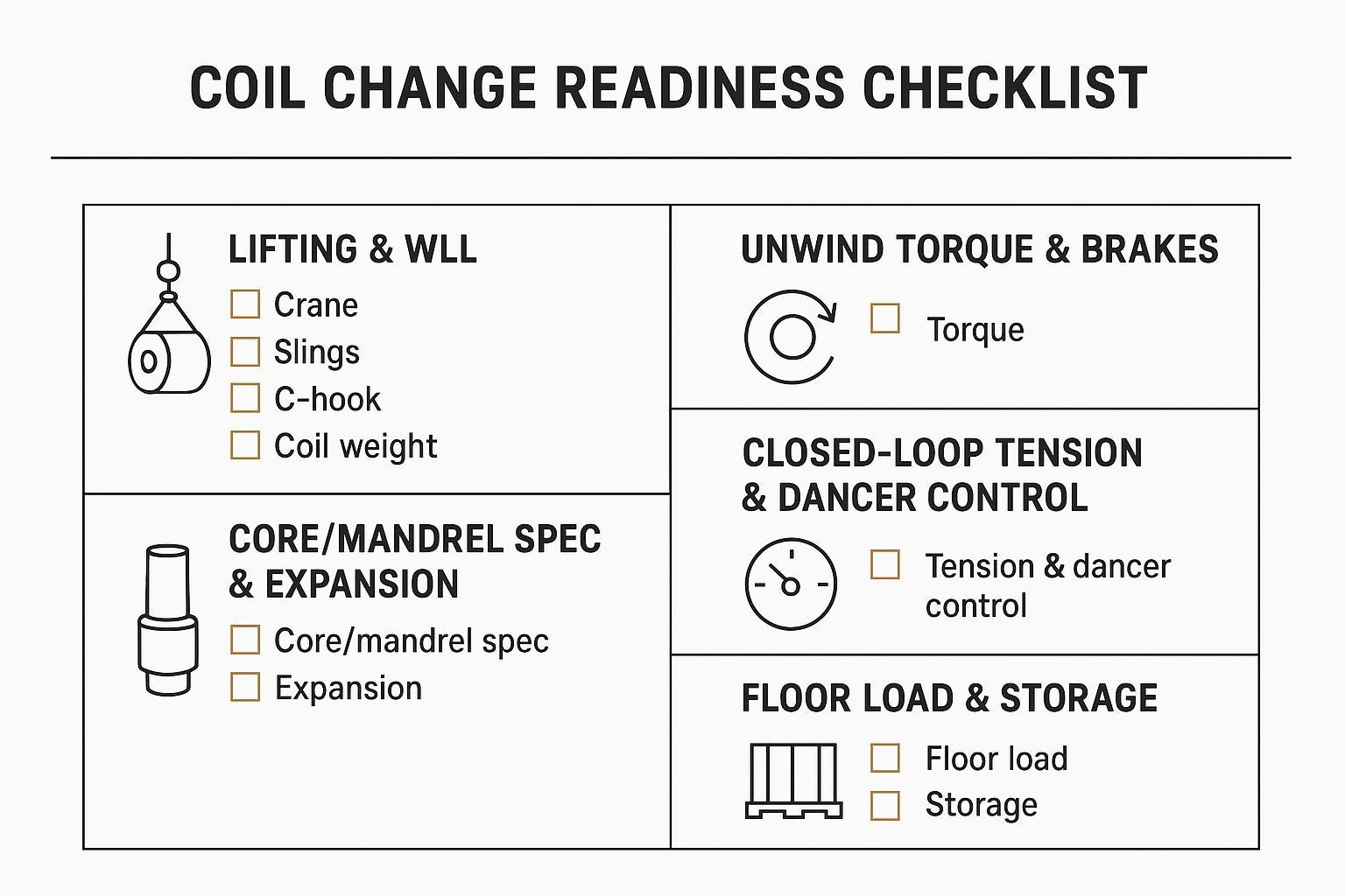
Update (or add) the following to standard work:
- Lifting plan: approved fixtures, WLL verification, exclusion zones, tag lines, and “hands-off” rules
- Lockout/tryout: isolate stored energy in brakes, pinch rolls, and tension systems before threading
- Threading method: defined path, guarding/interlocks, and safe hand positions
- Tension setpoints: start-up recipe and verification checks (what “stable” looks like)
- First-piece / first-meter validation: what to inspect after a change (tracking, edge condition, burr, surface)
Integration with auto-splicing and SMED
Reducing coil change frequency is one lever. Reducing the time and variability of the remaining changes is the other.
Two practical integrations:
- Auto-splicing (optional upgrade path): Auto-splicing can reduce the effective impact of coil changes by externalizing parts of the work and reducing restart variability. In many plants, it is a capital and integration decision (equipment capability, material compatibility, safety/guarding, and validation requirements), so it is not quantified in the simple equations above. Treat it as a next-step option after you baseline changeover time, scrap per change, and restart yield.
- SMED: The core SMED idea is to convert internal work (machine stopped) to external work (machine running), then standardize what remains. The method was developed by Shigeo Shingo and is documented in detail in A Revolution in Manufacturing: The SMED System. Productivity Press, 1985 (Primary source for SMED methodology.).
A simple SMED starter checklist for coil-fed lines:
- Pre-stage the next coil (ID verified, core verified, edge protected)
- Standardize threading tools and torque settings
- Use visual marks for alignment and strip path
- Parallelize the crew: one on mechanical change, one on verification and documentation
Caso piloto: Línea de fleje de acero para cuchillas 440C (anonimizado)
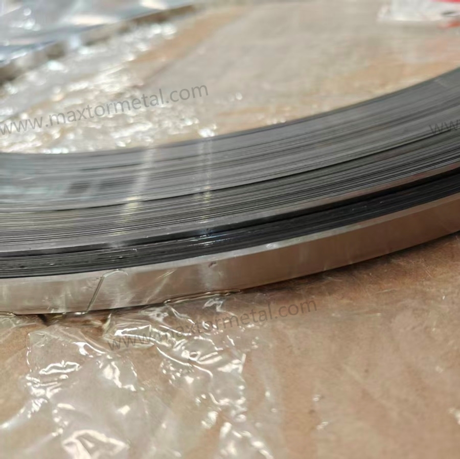
This anonymized case shows how a blade strip producer improved OEE by reducing coil change frequency while keeping product specs stable.
Project background
- Product: 440C blade strip steel, supplied to food-cutting blades and industrial band-knife makers
- Goal: reduce changeovers by increasing coil length (not by simply pushing rolling speed)
- Duration: ~5 weeks
- Data ownership and anonymization: This dataset was collected by Maxtor Metal’s technical team during a joint supplier qualification and process optimization project with the customer. Customer-identifying details have been anonymized with permission.
Preconditions (held constant)
- Same steel grade, thickness, width, and heat-treatment process
- Same crew/team; standardized changeover training
- No new equipment added (process + changeover workflow optimization only)
- First-coil validation performed each shift
- OEE accounting rules unchanged
Método de medición
Data dictionary (what each metric means)
| Data field | Definition (what to record) | Unidad | Typical source |
|---|---|---|---|
| metros_por_turno | Actual strip consumed during the shift | m/turno | MES + coil usage log |
| minutos_por_cambio | Time from changeover start to stable production (exclude external prep when possible) | min/cambio | Video time study + downtime log |
| metros_de_desecho_por_cambio | Scrap length tied to the splice/threading window (tail-out + threading scrap) | m/cambio | Measurement at splice + scrap log |
| changes_per_shift | Count of coil changes in the shift | count/shift | Operator record + downtime log |
| planned_downtime_min | Sum of planned stop minutes tied to coil changes | min/shift | Downtime log |
| availability_delta | Change in Availability points vs baseline | points | OEE report (same accounting rules) |
| oee_delta | Change in overall OEE points vs baseline | points | OEE report (same accounting rules) |
Note: In this pilot, “stable production” was defined as reaching the normal running window where tension, tracking, and quality checks passed the shift’s first-meter validation.
Per shift:
- record actual strip consumption (m/shift)
- time each changeover from start to stable production (min/change)
- measure scrap length around the splice/threading window (m/change)
- count changes per shift and sum planned downtime
- compute Availability and overall OEE deltas
Línea de base (antes)
| Artículo | Base |
|---|---|
| Longitud de la bobina | 1,000–1,200 m/coil |
| Blade strip consumption | 2,600–3,100 m/shift |
| Coil changes | 2–3 / shift |
| Tiempo de cambio | 16–20 min/change |
| Scrap generated | 7–10 m/change |
Video review suggested ~60% of stoppage time was not the physical coil swap itself, but delays such as finding lifting fixtures, aligning the coil head, waiting for confirmation, and re-stabilizing tension—this pattern is commonly addressed by SMED-style analysis (separating internal vs external work and standardizing what remains).
First improvement attempt (coil length only)
Coil length was increased by approximately 30% (from the 1,000–1,200 m baseline to ~1,300–1,550 m) without changes to the unwind parameters or changeover workflow. Change count per shift dropped as expected, but the team recorded:
- Higher inertia with larger OD — unwind tension fluctuated ±15–20% during the first 8–12 minutes after a change (vs ±5% at baseline)
- Slight strip snaking during the first ~20 minutes after a change, requiring operator intervention
- Scrap per change increased from the 7–10 m baseline to 11–15 m, partially offsetting the reduction in change count
- Net Availability improvement: near zero — fewer stops, but longer restart windows per stop
The team rejected this approach and concluded that coil length increases must be paired with unwind parameter re-tuning and standardized changeover work. The lesson: coil length is a system variable, not an isolated lever.
Final improvement (coil length + process + standard work)
Actions taken:
- increased coil length by ~35–45%
- re-tuned unwind parameters
- pre-staged tools and fixtures
- standardized coil-head positioning before stop
- used a checklist for changeover + restart verification
Results:
| Artículo | Antes | Después |
|---|---|---|
| Longitud de la bobina | 1,000–1,200 m | 1,400–1,700 m |
| Blade strip consumption | 2,600–3,100 m/shift | ~unchanged |
| Tiempo de cambio | 16–20 min/change | 11–14 min/change |
| Merma por cambio | 7–10 m | 4–6 m |
Improvement summary
| Métrica | Mejora |
|---|---|
| Coil changes per shift | ↓ ~25–35% |
| Planned downtime | ↓ ~35–45% |
| Changeover scrap | ↓ ~30–45% |
| Disponibilidad | + ~2–4 points |
| Overall OEE | + ~3–6 points |
Operator behaviors that mattered
High-performing crews typically:
- prepped the next coil ~10 minutes in advance
- confirmed fixtures and lifting plan before stopping
- loaded the correct unwind tension recipe early
- performed immediate first-meter checks after restart
Lower-performing crews tended to:
- search for tools after the line stopped
- delay first-coil checks
- rely on ad-hoc tension tuning
Even on the same equipment, the difference between shifts was often ~2–4 min/change.
Applicability limits
This approach is most effective when:
- production is stable (same grade/spec for long runs)
- coil weight/OD increases are within handling limits
- the unwind system can control higher inertia reliably
If your schedule frequently changes grade/width/spec, the benefits of longer coils may be offset by SKU changeovers—so combine coil length strategy with SMED, scheduling discipline, and standardized work rather than relying on coil length alone.

FAQ:
P: ¿Cómo afecta la frecuencia de cambio de bobina al OEE?
Cada cambio de bobina es una parada planificada dentro del tiempo de producción programado, lo que reduce directamente la Disponibilidad del OEE. También genera una ventana de reinicio donde el Rendimiento (aceleración de velocidad, estabilización de tensión) y la Calidad (defectos adyacentes al empalme, deriva dimensional) pueden disminuir. El efecto combinado convierte a la frecuencia de cambio de bobina en una de las palancas del OEE con un retorno de inversión más rápido en líneas alimentadas por bobina, ya que acumula tres pérdidas recuperables: tiempo de inactividad, mano de obra y desperdicio por empalmes.
P: ¿Cuál es un objetivo realista para el tiempo de cambio en una línea de fleje de cuchillas alimentada por bobina?
Basándose en los datos piloto de este artículo, un punto de referencia de 16–20 min por cambio es común antes de la optimización tipo SMED. Tras estandarizar el trabajo de preparación externa, preposicionar los utillajes y verificar la receta de desenrollado antes de la parada, el mismo equipo logró 11–14 min por cambio (una reducción de aproximadamente el 25–35%) sin añadir equipos. Las líneas con capacidad de empalme automático pueden reducir aún más el tiempo de cambio interno, pero la mayor ganancia individual suele provenir de convertir el tiempo reactivo de "buscar y encontrar" en trabajo externo preposicionado.
P: ¿Cómo calculo la pérdida de Disponibilidad del OEE debida a los cambios de bobina?
Utilice: tiempo_inactividad_min = (metros_por_turno / metros_por_bobina) × minutos_por_cambio. Divídalo entre el tiempo de producción programado para obtener el impacto en la Disponibilidad en forma de porcentaje. Por ejemplo, 20 cambios/turno × 12 min/cambio = 240 min de tiempo de inactividad planificado. En un turno de 8 horas (480 min), eso representa una pérdida del 50% en Disponibilidad solo por los cambios de bobina, antes de contabilizar cualquier parada no planificada.
For grid-blade lines where slot-bottom fractures are a recurring unplanned-stop source, see Stopping Grid Blade Snapping at Slot Bottoms for the geometry and metallurgical controls that reduce snap-related line interruptions.
P: ¿Afecta la longitud de la bobina a la calidad del fleje o al rendimiento de la cuchilla?
La longitud de la bobina en sí no influye en la calidad del fleje; lo importante es si el control de proceso del proveedor se mantiene a lo largo de toda la bobina. Las bobinas más largas amplifican cualquier deriva dimensional o inconsistencia en el tratamiento térmico: se procesa más material antes de detectar el problema. Por ello, el aumento de la longitud de la bobina debe acompañarse de una revisión de la documentación del proveedor y no tratarse puramente como una decisión logística. Específicamente para el acero en fleje para cuchillas, la tolerancia de espesor a lo largo de la bobina y el muestreo periódico de dureza son los dos indicadores de control de proceso más importantes que se deben solicitar al proveedor.
P: ¿Cuándo una bobina más larga no mejora el OEE?
Existen tres escenarios comunes donde el beneficio es limitado o negativo: (1) su programa de producción cambia de grado, ancho o especificación con frecuencia; los cambios de SKU compensan las ganancias de hacer menos cambios de bobina; (2) su sistema de desenrollado no puede controlar de manera confiable la mayor inercia de las bobinas con un diámetro exterior (OD) más grande, lo que genera inestabilidad en el reinicio y borra el ahorro de tiempo de inactividad; (3) su línea no es la restricción: si las operaciones de aguas abajo son el cuello de botella, recuperar tiempo de Disponibilidad en la línea de bobinas no se traduce en un valor de rendimiento adicional.
P: ¿Qué documentación debo solicitar a un proveedor de fleje de acero para cuchillas al cambiar a bobinas más largas?
Como mínimo: registros de tolerancia dimensional (espesor y ancho) muestreados a lo largo de toda la longitud de la bobina (no solo en los extremos), registros de lotes de tratamiento térmico vinculados a los números de lote de la bobina y registros de muestreo de dureza. Para aplicaciones de cuchillas en contacto con alimentos, también son relevantes los registros de pasivado y acabado superficial (Ra ≤ 0,8 µm). Maxtor Metal proporciona este paquete de documentación, estructurado para programas de auditoría de proveedores, a los clientes que califican el suministro de bobinas para aplicaciones de fleje de cuchillas.
For a step-by-step guide on how to read and verify these documents at incoming inspection — including EN 10204 3.1 certificate structure, chemistry cross-check against ASTM A681/ISO 4957, and 9-point hardness mapping — see the Tool Steel MTC Reading & QA Checklist for Strip Blades.
Conclusión
- Key gains: fewer changeovers, higher Availability, lower setup labor, less splice scrap
- Next steps: plug in plant data, validate with a short pilot, review handling and safety limits
Reducing coil change frequency is a clean OEE play because it attacks a visible loss bucket: planned downtime for changeovers. The ROI often survives conservative assumptions because you’re stacking three effects—Availability time back, fewer labor-minutes tied up in non-value-added work, and fewer splice-related scrap events.
If you want this to hold up in a technical review, treat coil length as a process capability question, not only a purchasing question. Longer stable runs require consistent heat treatment and tight dimensional control over the whole coil—which means your supplier’s QC documentation is part of the equation, not just the strip price.
Maxtor Metal supports customers running formal coil supply validation programs with batch-level documentation: dimensional tolerance records across coil length, heat-treatment consistency data, and hardness sampling logs formatted for audit-ready review. If your internal review requires a concrete long-coil supply spec as a reference point, the acero en fleje para cuchillas industriales en bobinas biseladas de Maxtor Metal product page is the relevant starting point.
Once coil change frequency is optimized, the next operational lever is blade lifecycle management. A structured regrind program — with measurable scrap/regrind thresholds and proactive sharpening intervals — can reduce annual knife consumable costs by 45–60%. See the Regrinding Industrial Strip Blades: Sharpening vs Scrap Guide for the full decision framework.
Referencias
Notas de transparencia
- Última actualización: 2026-07-11
- Aviso legal: This article includes a product example from Maxtor Metal for illustration. The OEE model and the pilot methodology can be applied with any qualified coil supplier.
- How the pilot data was measured: The pilot section summarizes an anonymized 5-week field trial with consistent OEE accounting rules, per-change time studies, and measured scrap length around the splice/threading window. In this context, changeover time means from changeover start to stable production (exclude external prep where possible), and scrap per change means tail-out + threading scrap measured around the splice/threading window.
- Nota de seguridad: Always follow your site’s safety procedures, lifting plans, and equipment OEM instructions when changing coils or tuning tension systems.
- ISO. ISO 22400-2:2021 — Automation systems and integration — Key performance indicators (KPIs) for manufacturing operations management — Part 2: Definitions and descriptions. https://www.iso.org/standard/54497.html
- Shingo, S. A Revolution in Manufacturing: The SMED System. Productivity Press, 1985. (Primary source for SMED methodology.) https://books.google.com.pe/books?id=ooXVVIfqEQwC&printsec=frontcover
- OSHA. “Materials Handling and Storage (OSHA 2236).” https://www.osha.gov/sites/default/files/publications/OSHA2236.pdf
- OSHA. “OSHA procedures for safe weight limits when manually lifting (Standard Interpretations).” https://www.osha.gov/laws-regs/standardinterpretations/2013-06-04-0
- ASME. ASME B30.20 — Below-the-Hook Lifting Devices. American Society of Mechanical Engineers. https://www.asme.org/codes-standards/find-codes-standards/b30-20-hook-lifting-devices
Tommy Tang es un ingeniero de ventas sénior en Maxtor Metal with 12 years of experience supporting industrial customers with custom blade and blade strip supply, including coil-fed cutting and slitting applications. He holds Ingeniería Informática, Educación médica continua, Cinturón Verde Six Sigma, y PMP credentials, and focuses on helping engineers and technical buyers reduce downtime risk through material selection, dimensional consistency, and audit-friendly quality control.

 English
  Spanish
  Italian
  French
  Portuguese
  Russian
  German
  Arabic
  Hindi
Hindi  Vietnamese
  Indonesian
  Japanese
  Korean