

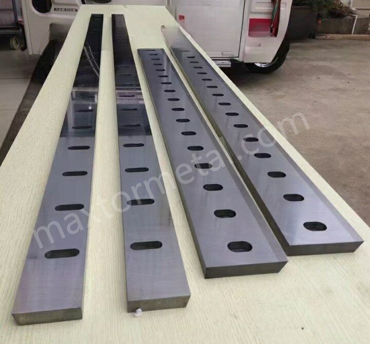
要約(Quick Answer): 超硬(タングステンカーバイド)ろう付けシャーブレードは、AHSS(超高張力鋼)ラインにおいて従来のD2(SKD11相当)刃具の2〜3.5倍の刃先寿命を実現します。そのROI(投資対効果)の源泉は、刃物本体の initial cost ではなく、刃具交換(段取り)回数の削減とエッジ不安定化に伴う歩留まりロス(不良廃棄)の抑制にあります。この寿命倍率を実際の量産ラインで維持できるか否かは、適切な刃先クリアランス管理と、再研磨時における刃先幾何形状の正確な復元管理の2点にかかっています。
ウルトラハイスループットなAHSS/UHSS(超高張力鋼)加工ラインの停止原因は、単に刀具が「切断できない」ことにあるわけではありません。刃先のチッピング(欠け)、バリ高さのばらつき、負荷時のクリアランス変動、再研磨形状の不均一といった微小な不安定要素が、静かにライン停止(ダウンタイム)、歩留まり低下(スクラップ)、そしてOEE(設備総合効率)の損失へと繋がるのです。
本ガイドは、AHSS(超高張力鋼)対応のシャーリング・シャーライン(Cut-to-Length)およびギロチンシャー設備を運用(または導入検討)されている生産・保全責任者、プロセスエンジニア、ならびに工程技術購買担当者様向けに作成されています。超硬(タングステンカーバイド)ろう付け刃具の導入評価において重要なのは、単なる「刃物寿命〇〇倍」といった表面的な数値を追うことではありません。鋼種構成(材種ミックス)、刃具交換段取り時間、そして再研磨のターンアラウンド(運用サイクル)時間までを網羅した、現場で再現性の高いROI算定モデルを構築することにあります。
一般的なせん断刃の構成と注文形式については、以下から始めてください。 Maxtor Metal せん断刃 ページにアクセスし、以下のモデルとチェックポイントを使用して、特定の製品ラインへの適合性と経済性を検証してください。.
- このガイドの対象者とAHSS/UHSSの状況
- 超高スループットにおけるブレードの選択とメンテナンスの変化
- タングステンカーバイドインレイ加工されたせん断刃が、寿命、バリ制御、および総所有コスト(TCO)に及ぼす影響
AHSS(超高張力鋼)のせん断加工では、高強度に伴う発熱や凝着(アブレシブ/アドヒーシブ摩耗)の激化、ならびに設備系の公差累積(設備のたわみ・クランプ力・平行度)の影響増大により、適正な「切断条件の許容幅(Cutting window)」が極めて狭くなります。WorldAutoSteelのAHSS加工ガイドラインによると、適正クリアランス(刃先隙間)は鋼材強度に比例して拡大し、普通鋼(マイルドスチール)の板厚比約6%から、引張強度1400 MPaを超える超高張力鋼では約16%以上まで増大します。また、AHSSでは普通鋼と異なり「バリ高さ」が刃物摩耗の判定指标として信頼しにくいため、エッジ品質(剪断面形状)の直接監視がより重要であると指摘されています。
超高スループット環境で求められるのは、単に「より硬い」刃具を使うことではありません。計画的なメンテナンス期間中も刃先の安定性を維持できる体系的な dynamic system — すなわち、予測可能な再研磨インターバル、適切に管理された刃先処理(Edge Prep)、そしてロット間の形状変動(漂移)を防ぐQC(品質管理)フィードバック機構こそが不可欠です。
タングステンカーバイドを象嵌したせん断刃は、主に3つの実用的な理由から評価されることが多い。
- 最先端の耐摩耗性 (特に勾配や路面状況が変化する場合)
- バリ取りを長期的に行う (刃先が鈍くなるにつれてドリフトが少なくなる)
- 総所有コスト(TCO)の削減 段取り替え、再研磨、スクラップを考慮すると
技術ノート:タングステンカーバイド象嵌せん刃は、D2またはH13合金鋼本体にろう付けされたタングステンカーバイド刃先を一体化した精密切削工具であり、切削面において工具鋼の靭性とカーバイドの耐摩耗性を兼ね備えています。AHSSおよびUHSSせん断ラインでは、この構造により、再研磨間の刃先安定性が向上し、様々なグレードや表面条件下におけるバリのずれが低減されます。ただし、クリアランス制御、アライメント、および再研磨後の形状復元が維持されていることが前提となります。[→ Maxtor Metalせん断刃の技術概要を参照してください。]
超硬(タングステンカーバイド)ろう付けシャーブレードの性能ベンチマーク
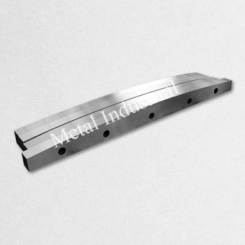
D2鋼/高バナジウム鋼に対する寿命増加率
超硬合金を組み込んだブレードは、現在の故障モードが エッジブレイクダウン (微細な欠け、エッジの摩耗の加速、バリの不安定性)が、単発的な機械的衝突ではなく発生する。.
普遍的な「X倍の寿命」という主張に頼るのではなく、植物で測定可能な2つの指標でベンチマークを設定しましょう。
- 鋭利な刃先1本あたりのメートル(またはトン) 品質基準に達するまで
- トリガーまでの時間安定性 異なるグレードの鋼材を混在させる場合(HSLA鋼からAHSS鋼に切り替えた際に、同じブレードが2つの異なる工具のように動作してはならない)
D2鋼や高バナジウム工具鋼と比較する有効な方法は、上位2~3種類の鋼種と、1つの「最悪ケース」条件(コーティング材、表面スケールの増加、または最もバリに敏感な下流工程)で、制御されたパイロット試験を実施することです。このガイドの後半で説明するROIモデルを使用すると、観測された寿命比率をメートル/トンあたりのコストに変換できます。.
象嵌の深さ、エッジの仕上げ、マイクロホーニングのターゲット
AHSSラインの場合、エッジは2つの役割を同時に果たす必要があります。つまり、摩耗や接着による摩耗に耐えつつ、脆性による欠けを防ぐのに十分な強度を維持しなければなりません。.
結果に大きく影響する3つの要因は以下のとおりです。
- 象嵌の深さ: 一般的に、インレイが深いほど、インレイの限界に達するまでに必要な再研磨回数が多くなります。.
- エッジ仕上げ切削面の表面仕上げは、摩擦、発熱、および接着に影響を与える。.
- マイクロホーニング制御されたマイクロホーニングは「刃先の脆さ」を軽減し、特に刃の長さ全体にわたってクリアランスが完全に均一でない場合に、刃先の安定性を向上させることができます。.
最適な目標値は、厚み、強度、そしてラインがバリ制限型か形状制限型かによって異なります。重要なのは、再研磨によってマイクロホーニングが徐々にずれてバリの挙動が変わってしまうことを防ぐため、合格基準を明確に定めることです(品質管理の項を参照)。.
一般的な目安として、ギロチン式およびCTL式せん断刃の場合、インレイの幅は3~6mm程度が一般的です。インレイの深さは、刃の厚さの許容値と必要な再研磨サイクルの総数によって決まります。.
Maxtor Metalでは、超硬合金を象嵌したせん断刃は、象嵌形状と研磨後の表面仕上げの記録が文書化されて製造されており、工場で確立されたマイクロホーニングと切削面の仕様が再研磨サイクル全体を通して追跡可能であることを保証しています。.
再研磨間隔トリガーと典型的なカウント数
軟鋼の場合、バリの高さは摩耗に伴って上昇することが多く、バリの発生を容易に判断できる要因となります。一方、AHSS(超高張力鋼)の場合、WorldAutoSteelのAHSSガイドラインでは、工具の摩耗が進んでもバリの高さは比較的一定に保たれる可能性があるため、より広い範囲でバリの発生を検知できる設定の方が安全であると指摘しています。.
使用 2つのトリガー: 1つ エッジ品質 そして1つは リスク.
- エッジ品質トリガー(下流工程で最も厳しくペナルティを課す項目を選択してください):
- 破砕帯の粗さのずれ
- 不均一な研磨/破断遷移
- バリのずれに関連する目に見える微細な欠けや線状の跡
- リスク発生の引き金:
- 位置合わせの不具合による切り替え時間の増加
- 公差を維持するために調整頻度を増やす
- グレード変更後にスクラップ発生件数が急増した。
これらのトリガーセットは、次のような一般的な検索クエリに直接対応します。 せん断刃の再研磨間隔 また、オペレーターが介入すべきタイミングを標準化するのに役立ちます。.
一般的な再研磨回数は、インレイの深さ、刃の厚み許容値、および各サイクルで形状がどれだけ正確に復元されるかによって異なります。実用的なポイントは、予想されるサイクル数の範囲を予測できる必要があるということです。 前に ROIモデルはそれに依存しているため、あなたはコミットする必要があります。.
段取り(セットアップ)と損傷・不具合対策
投資対効果(ROI)の成否は、主にセットアップにかかっています。不安定なセットアップで高性能ブレードを使用しても、高価な消耗品となってしまいます。.
あなたの最大の不満は AHSSせん断におけるバリ制御 連続して加工する場合、通常最も重要な 2 つのレバーは、(1)端から端までクリアランスの均一性を維持すること、および(2)再研磨後にエッジの準備状態を一定に保つことです。一定の周期(コイル数またはシフト)でエッジゾーンの外観をサンプリングし、調整頻度と再研磨イベントとの相関関係を調べます。.
薄肉AHSSおよびステンレス鋼のクリアランス目標
薄いAHSSとステンレス鋼の場合は、 厚さに対するクリアランスの割合, 次に、実際のクランプ条件下で、それがエンドツーエンドで一貫していることを確認します。.
WorldAutoSteelの AHSSガイドライン クリアランスは強度とともに一般的に増加する(高強度領域では約6%から約16%+まで)ことを議論し、また、クリアランスが小さすぎても大きすぎても、それぞれ異なる破壊モードが発生することを警告する。.
まず、具体的な目標値を設定し(その後、試し切りとエッジ検査で検証する):
- AHSSせん断刃のクリアランス: で始める 厚さ10~16% より高い強度が必要な場合は範囲を指定し、エッジの外観やひび割れ感受性に基づいて調整してください。.
- ステンレス鋼(薄板): しばしば必要とする 軟鋼よりも高いクリアランス 二重せん断や過度の加工硬化を避けるため、エッジゾーンの外観とバリの発生状況で検証する。.
重要なポイントAHSSの場合、バリの高さだけを「クリアランスが適切」の指標として扱わないでください。切削エッジゾーン全体の挙動と安定性を長期的に監視してください。.
位置合わせ、すくい角、均一なクランプ
AHSS(人文社会科学)の分野において、もし一つだけ変更を加えるとしたら、以下の点にしてください。 平行度とクランプの均一性を品質変数として扱い、保守変数として扱わない。.
- 位置合わせ:刃の両端だけでなく、刃の長さに沿った複数の点で平行度を確認してください。.
- すくい角:使用する材料の種類に合わせて適切なすくい角を選択してください。極端な角度は力を軽減できますが、薄い材料の変形パターンが変わる可能性もあります。.
- クランプ:不均一なクランプは局所的なクリアランスのスパイクを生み出します。これらのスパイクは、チッピングが始まる場所であり、バリのずれが「不可解」になる場所でもあります。“
熱、接着、およびエッジ準備戦略
AHSSとステンレス鋼は、2つの問題を増幅させる。 熱 そして 接着.
- 熱:負荷の増加と摩擦によって局所的な軟化が生じ、摩耗が加速する可能性があります。また、刃先が鋭利すぎる場合、熱によって微細な欠けが発生するリスクも高まります。.
- 付着性:特にステンレス鋼は「付着」しやすく、塗り広げられることがあります。これにより、有効なクリアランスが変化し、エッジマーキングの原因となる可能性があります。.
行動を安定させる傾向のある、エッジ準備戦略:
- 繊細なカミソリの刃ではなく、制御されたマイクロホーニングを使用する
- 再研磨後も切削面の仕上げを一定に保つ
- 接着力が主な問題である場合は、表面の状態と清掃方法に重点を置く(接着層は形状変化となる)。
再研磨プロトコルおよび品質管理(QC)基準
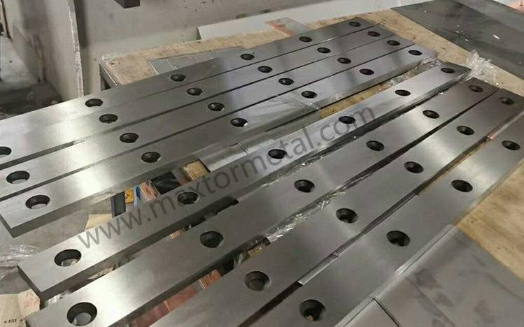
象嵌の制限、再研磨のステップ数、および許容される総サイクル数
超硬合金の象嵌により、再研磨の質問は「何回研げるか?」から「何回研げるか?」に変わります。 インレイシステムに妥協する前に?”
プロトコルでは以下を定義する必要があります。
- 最小残存インレイ深さ(停止点)
- 再研磨1回あたりの最大許容厚さ減少量
- 刃先加工(マイクロホーニング)をサイクル全体にわたって維持する方法
- 刃が「再研磨可能」か「廃棄」かを判断するためのルール(ひび割れ、ろう付けの健全性に関する問題、形状の歪みなど)
各再研磨サイクル後の厚み減少を補正するために使用されるシム計算方法については、以下を参照してください。 再研磨による厚み減少補正とシムスタックガイド.
形状復元、表面粗さ(Ra)、および合格基準
再研磨の投資対効果は、形状復元が適切に行われた場合にのみ有効です。.
推奨される受入基準のカテゴリ:
- 幾何学
- 刃先の直線性
- 全長にわたる平行性
- 一貫した面取り形状(「角が丸くなる」ようなずれがない)
- 表面仕上げ
- 切削面の仕上げは、管理可能で再現性のあるものでなければならない(Ra値または同等の表面粗さ測定法を追跡する)。
- 境界条件
- 設定したしきい値を超えるマイクロチップ埋め込みは行いません
- 一貫したマイクロホーニング(「毎回よりシャープになる」というずれを許容しない)
Maxtor Metalの研磨後受入プロトコルは、上記の3つのカテゴリ(形状、表面仕上げ、エッジ状態)すべてを網羅しており、各再研磨バッチごとに追跡可能な検査記録が返却されます。.
図面における端部要件の文書化に関しては、技術製品文書において未定義の端部要件を示すための標準規格はISO 13715:2017です。たとえ直接この記号体系を使用しない場合でも、社内の受入基準を認知された標準規格に合わせることで、各工程、サプライヤー、再生材供給業者間の曖昧さを軽減できます。.
Maxtor Metalは、工程内品質管理チェックによる超硬合金象嵌ブレードの製造をサポートし、追跡可能な検査記録付きの再研磨サービスを提供することで、形状とバッチの一貫性を維持するのに役立ちます。.
文書、MTC、およびバッチ整合性チェック
AHSSラインの場合、調達リスクは変動の中に隠れていることが多い。 同じ 部品番号は、製造ロットによって挙動が異なる。.
各バッチの実用的なドキュメントパックには、以下が含まれるべきです。
- MTC / 材料トレーサビリティ ベース本体および該当する場合はインレイ材
- 硬度/熱処理に関する証拠(該当する場合)
- 主要寸法(厚さ、真直度、平行度)に関する検査報告書
- 再研磨履歴ログ(サイクル数、除去された材料、研磨後の検査)
これは必ずしも官僚的な手続きである必要はありません。重要なのは、バリのずれや欠けが見られた際に、根本原因の究明作業を迅速に行うことです。つまり、設定の問題と製造ロットのばらつきを切り離して考えることができるのです。.
TCO(総保有コスト)およびROI(投資対効果)算出モデル
入力、計算式、償却ロジック
以下のTCO構造は、Maxtor Metalが高スループットAHSSラインとのコストに関する議論をどのように捉えているかを反映しています。つまり、ブレードの価格ではなく、1メートルあたりの総コストです。.
有用な ROI モデルは「ブレード寿命」を 1メートルあたりのコスト (または 1トンあたりのコスト)さらに、高スループットラインで一般的に発生するコスト、つまりダウンタイムと不良品のコストも加算されます。.
これは実用的な基盤となるものです 剪断刃の総所有コスト 比較すると、あらゆる前提条件(寿命、再研磨回数、段取り替え時間)を同じ単位に押し込めてしまうからです。.
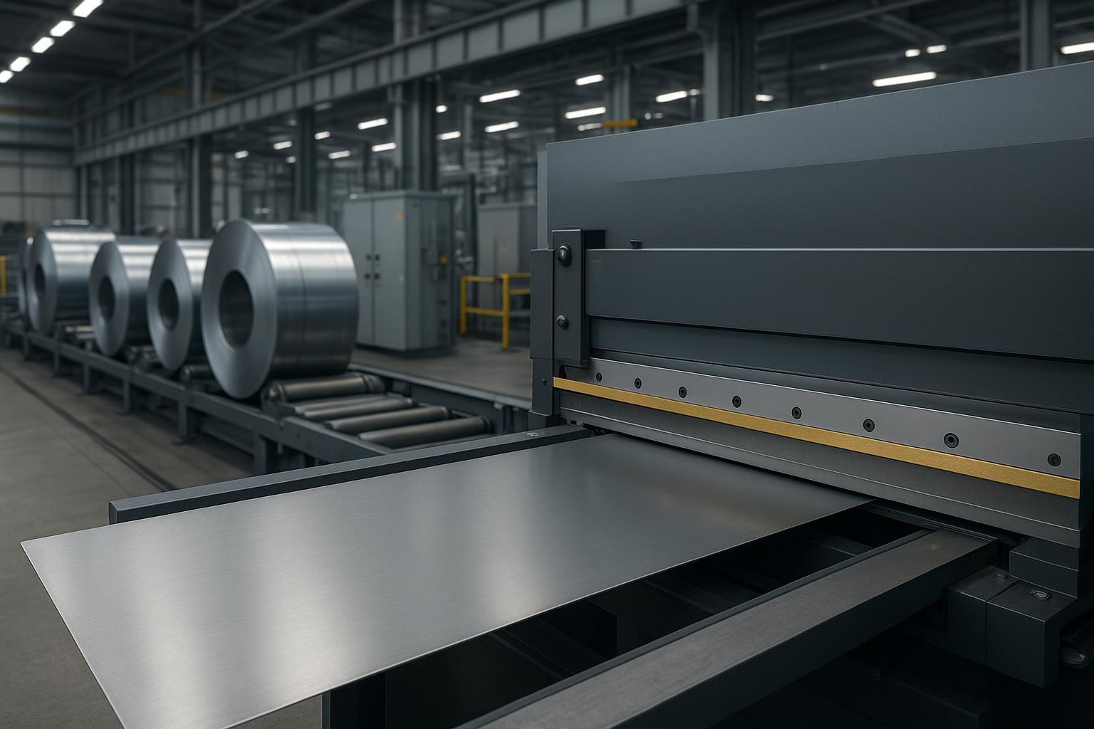
これらの入力を定義します。
Cブレードブレードセット1セットの購入費用N_エッジ:セットあたりの使用可能なエッジ数(該当する場合は反転/回転を含む)L_edge:再研磨/交換間の刃先1本あたりのメートル(またはトン)N_regrinds: スクラップになるまでに達成可能な再研磨の総回数(インレイの制限値+形状公差によって制限される)C_再研磨: 再研磨サイクルあたりのコストT_changeイベントごとの切り替え時間(時間)C_ダウンタイム: フル稼働時のダウンタイムコスト(1時間あたり)C_scrap:1トンあたり(または1メートルあたり)のスクラップ/再加工コストS_scrap:切断刃先の不安定性に起因する不良率(割合)
シンプルな償却構造:
- ブレードの償却費(メートル当たり)
コピー&ペースト可能なROI計算テンプレート
Excelに簡単に移行できるテンプレートが必要な場合は、この表から始めて、独自の行データを入力してください。単位は統一してください(メートル、 または 各列にトン)が並んでいます。.
| 入力 | シンボル | あなたの価値 | 単位/注記 |
|---|---|---|---|
| ブレードセットの購入費用 | Cブレード | 1セットあたり$ | |
| セットあたりの使用可能なエッジ | N_エッジ | カウント(反転/回転を含む) | |
| エッジごとの寿命をトリガーする | L_edge | メートル/辺またはトン/辺 | |
| スクラップになる前の再粉砕総量 | N_regrinds | 個数(インレイ+許容誤差の範囲内) | |
| サイクルあたりの再研磨コスト | C_再研磨 | 再研磨1回あたり$ | |
| イベントごとの切り替え時間 | T_change | 時間/イベント | |
| ダウンタイムコスト | C_ダウンタイム | $/時間(フル稼働時) | |
| スクラップコスト | C_scrap | $/トンまたは$/メートル | |
| 切断刃の不安定性による不良率 | S_scrap | 分数(例:0.009 = 0.9%) | |
| 出力 | 式 | 結果 | 注記 |
| — | — | — | — |
| ブレードセットの総寿命 | 合計_m | N_edges × L_edge × (N_regrinds + 1) | メートルまたはトンを常に使用する |
| ブレードの償却費(単位当たり) | ブレード1枚あたりのコスト(メートル単位) | C_ブレード / 合計m | $/メートルまたは$/トン |
| 単位当たりの再粉砕コスト | 1メートル当たりの再研磨費用 | (C_regrind × N_regrinds) / Total_m | $/メートルまたは$/トン |
| ユニットあたりのダウンタイムコスト | メートル当たりのコスト削減額 | (T_change × C_downtime × (N_regrinds + 1)) / Total_m | 簡略化しました。予定外のイベントがあれば追加してください。 |
| 単位当たりのスクラップコスト | スクラップ費用(メートル当たり) | S_scrap × C_scrap | 必要に応じて単位を変換してください。 |
| 単位当たりの総コスト | TCO_per_m | 上記のすべての費用の合計 | ベースラインと超硬合金インレイを比較 |
このレイアウトにより、ベースラインシナリオと超硬合金象嵌シナリオの両方で同じモデルを簡単に実行し、差分(総所有コスト削減、回収期間、投資収益率)を計算できます。.
刃1メートルあたりのコスト = 刃のコスト / (刃の枚数 × 刃の長さ × (再研ぎの回数 + 1))- 1メートルあたりの再研磨費用
1メートルあたりの再研磨コスト = (再研磨コスト × 再研磨回数) / (エッジ数 × エッジ長 × (再研磨回数 + 1))
- メーターあたりのダウンタイムコスト (段取り替え+再研磨)
1メートルあたりのコスト = (変更時間 × ダウンタイム × イベント総数) / 総メートル数
次に、スクラップを追加します。
スクラップコスト(mあたり)= S_scrap × C_scrap(単位変換は一貫性を保つ)
ROIの比較は、以下の差分です。
ROI = (TCO_baseline - TCO_carbide) / Investment_delate
プレースホルダーを含む、メートル/トンあたりのコスト例
以下は計算例です 例 計算結果の挙動を示すためにサンプル値を使用しています。数値を実際のデータに置き換えてください。.
仮定する:
C_blade = $6,000セットあたりN_edges = 2L_edge = 200,000 mN_regrinds = 6C_regrind = $450
生涯を通じて1セットあたりの総メートル数:
Total_m = N_edges × L_edge × (N_regrinds + 1) = 2 × 200,000 × 7 = 2,800,000 m- ブレードの償却費(メートル当たり):
$6,000 / 2,800,000 = $0.00214/m
- 再研磨費用(メートル当たり):
($450 × 6) / 2,800,000 = $0.00096/m
主なコストがダウンタイムである場合、切り替え時間によって投資対効果(ROI)が大きく変動するでしょう。.
ダウンタイム入力例:
T_change = 0.5時間イベントごとC_downtime = $3,000/時間イベント総数 = 7(初回+再研磨6回)
メーターあたりのダウンタイムコスト:
($3,000 × 0.5 × 7) / 2,800,000 = $0.00375/m
この簡単な例は、「ブレード単価」が必ずしも決定的な要素ではない理由を示しています。切り替え時間と安定性イベントは.
ギャップ制御、グレードミックス、および再粉砕SLAに対する感度
通常、以下の3つの感度調整機能が支配的になります。
- ギャップ制御(クリアランスの均一性)
- ギャップコントロールが不十分だと、刃こぼれを引き起こし、早期の再研磨を余儀なくされることで、せっかくの寿命延長効果が帳消しになってしまう可能性があります。.
- 路盤の配合(強度+路面状態)
- 加工対象がより高強度のAHSS(高強度鋼板)になったり、表面の摩耗性が高くなったりする場合は、エッジの安定性がより重要になります。.
- 再生研磨SLA(納期+品質の一貫性)
- 研磨作業が遅かったり、一貫性がなかったりすると、予備部品の在庫要件が増加し、形状ずれが発生する可能性が高まります。.
財務的に分かりやすい感度分析結果を1つだけ作成したい場合は、以下の項目のみを変更して、3つのシナリオ(保守的/予想/楽観的)の下でTCOをモデル化します。
L_edge(人生)T_change(切り替え時間)S_scrap(エッジの不安定性に起因する破片)
過学習を起こさずに感度を簡潔に示す方法は、高スループットラインにおける総所有コスト(TCO)を左右する一般的な前提条件のみを変化させることである。.
| シナリオ | エッジあたりの寿命 L_edge | 切り替え時間 T_change | エッジ不安定性スクラップ S_scrap | それが表すもの |
|---|---|---|---|---|
| 保守的 | パイロットバンドの下限 | 観測された変化の上限値 | エッジ関連のスクラップの上限 | セットアップ時のずれ、表面状態の粗さ、再研磨の所要時間の遅延 |
| 期待される | パイロットバンドの中央値 | 中央値の変更 | 中央値のスクラップ帰属 | 通常の作業ペースとグレード構成 |
| 楽観的 | パイロットバンドの上限 | 下限値切り替え(ベストプラクティスSOP) | 下限スクラップ帰属 | 厳密なクリアランス制御 + 一貫した再研磨 + 安定した材料 |
結果を発表する際は、 範囲 (単一の数値ではなく)1メートル/トンあたりの総所有コスト(TCO)と、回避できたダウンタイム分数を示します。これにより、単一の投資収益率(ROI)の数値よりも、ビジネスケースの信頼性が高まります。.
導入・運用プレイブック(実践ガイド)
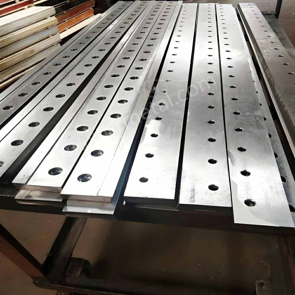
切り替え、検査、および再粉砕物流に関する標準作業手順書(SOP)
以下の3つの標準作業手順書(SOP)は、すべてのパイロット運用環境に適用され、本格的な生産に移行する前に確定しておく必要があります。.
バリしきい値バンド、エッジ使用順序、監査対応ログテンプレートなど、ギロチン式せん断刃に適用可能な測定ベースの回転および再研磨決定SOPの完全な詳細については、以下を参照してください。 4枚刃リバーシブルブレードの回転スケジュールと再研磨基準に関する標準作業手順書(SOP).
パイロットテスト結果:3つの匿名化事例サマリー
投資対効果(ROI)に関する決定を最も迅速に正当化する方法は、小規模で管理されたパイロット試験を実施し、その結果を工場で既に追跡している単位(再研磨間のコイル数、バリの安定性、セットアップ介入、不良品/再加工、OEE時間など)で報告することです。.
以下は、超硬合金を象嵌したブレードが最初に効果を発揮する場所を示す、匿名化された3人のパイロットです。 構造, これは約束ではありません。結果は、グレードの配合、クリアランス管理、クランプの再現性、および再粉砕の一貫性によって異なります。.
パイロットケース1 — DP980におけるAHSS CTL
コンテクスト
- 材質:DP980(980~1000MPa)
- 厚さ:1.2~2.0 mm
- ライン:コイル・トゥ・レングス(CTL)
- コイルの状態:酸洗・油処理済み、軽度のミルスケールあり
- 刃:超硬合金象嵌刃:D2鋼本体+ろう付けされた超微細WC刃、Maxtor Metal社製
ベースライン構成と炭化物埋め込み構成の比較
- ベースラインブレード:D2工具鋼、硬度60~61HRC
- 超硬合金象嵌ブレード:D2鋼(硬度59~60HRC)本体+ろう付けされた極細WCエッジ
- 超硬合金の幅:4mm
- 刃先硬度:約89 HRA
トリガーと測定
- ベースラインで約40~50個のコイルを巻いた後にトリガーが作動します。
- バリの高さが0.10mmに近づく
- ブレードクリアランス調整頻度の増加
- 初回の検査をより頻繁に行う
- 測定手順:
- コイルあたり:50倍の工具顕微鏡を使用して左/中央/右で測定したバリの高さ
- 10コイルごとに、最大バリ、クリアランス、エッジ半径を記録します。
パイロット試験の結果
| KPI | ベースラインD2 | WC象嵌 |
|---|---|---|
| 刃の寿命 | 1.0× | 2.9× |
| 再研磨間のコイル | 48 | 138 |
| 平均的なバリ | 0.082 mm | 0.039 mm |
| 予期せぬセットアップイベント | 月5回 | 月2回 |
| スクラップ | 1.8% | 0.9% |
| OEE | 84.1% | 87.6% |
| 再生SLA | — | 5営業日 |
このパイロットが教えてくれたこと
- DP980の研磨性の高さが、刃先の摩耗安定性を最重要課題とした。.
- 当初D2で使用されていたクリアランス設定をそのまま維持したところ、局所的な微細な欠けが発生した。クリアランスをわずかに最適化することで、安定した動作が回復した。.
パイロットケース2 — 大量のミルスケールが付着したギロチンライン
コンテクスト
- 材質:熱間圧延AHSS
- 厚さ:4~8mm
- ライン:油圧式ギロチン
- 表面:厚いミルスケール
- 刃:超硬合金象嵌刃:H13鋼本体+ろう付けされた超微細WC刃、Maxtor Metal社製
ベースライン構成と炭化物埋め込み構成の比較
- ベースラインブレード:改良型H13
- 超硬合金象嵌ブレード:H13鋼本体+ろう付けタングステンカーバイド刃;二重焼き戻し
トリガーと測定
- スケールによる摩耗はバリを増加させ、頻繁なセットアップ調整を余儀なくさせた。.
- 測定:
- シフトごとに、バリ、刃先半径、刃の温度をチェックする。
- 毎週:直線性と平面性を確認する
パイロット試験の結果
| KPI | 前に | 後 |
|---|---|---|
| 刃の寿命 | 1.0× | 2.1× |
| 毎月のブレード交換 | 4 | 2 |
| セットアップ時間 | 月150分 | 月70分 |
| リワーク | 2.4% | 1.3% |
| エッジの欠け | 時々 | 大幅に減少 |
| 再生SLA | — | 7暦日 |
このパイロットが教えてくれたこと
- ミルスケールは依然として主要な摩耗原因であった。超硬合金は耐摩耗性を向上させたが、スケールを除去しない場合、寿命の延長効果は酸洗・油処理条件下よりも低かった。.
パイロットケース3 — 大量生産自動車CTL
コンテクスト
- 材質:CP780 + DP780
- 厚さ:1.6~2.5mm
- ライン:高速CTL
- 年間生産量:60,000トン以上
- 刃:超硬合金象嵌刃:D2鋼本体+ろう付けされた超微細WC刃、Maxtor Metal社製
ベースライン構成と炭化物埋め込み構成の比較
- ベースラインブレード:プレミアムD2
- 超硬合金仕様:微細粒WC、真空ろう付け
- 研削後の表面粗さ目標:Ra ≤ 0.2 μm
トリガーと測定
- 高頻度での作業には計画的な週ごとの停止が必要となり、バリが下流の溶接品質に影響を与え始めた。.
- 測定:
- 最初のピース:バリの高さ
- 20コイルごとに顕微鏡検査、クリアランス、エッジ半径
- 再研磨のたびに:平面度、平行度、厚み
パイロット試験の結果
| KPI | 前に | 後 |
|---|---|---|
| 刃の寿命 | 1.0× | 3.4× |
| 再研磨間隔 | 2週間 | 7週間 |
| マックスバー | 0.11 mm | 0.05 mm |
| 計画的なメンテナンス | 月9時間 | 月4時間 |
| 顧客の優位性に関する主張 | 四半期に3回 | 四半期あたり0~1回 |
| 推定総所有コスト | ベースライン | 約18%の削減(ブレード償却費+再研磨費+交換費用;上記のTCOモデルを使用して計算) |
| 再生SLA | — | 3~4営業日 |
このパイロットが教えてくれたこと
- 固定回転数と再研磨スケジュール、および再取り付けチェック(平行度とクリアランス)により、取り付け時のばらつきが工具の差異を覆い隠すことを防ぎました。約18%のTCO削減は、主に再研磨間隔の延長(2週間→7週間)と計画ダウンタイムの削減(月9時間→月4時間)によるもので、このスループットレベルではブレード償却費の寄与は小さくなっています。.
コピーできるシンプルなパイロット記録
パイロット版の内容を1枚のシートにまとめて、財務部門と制作部門が同じ言語でコミュニケーションできるようにしましょう。
- グレード + 厚さ範囲 + 表面状態
- メートル/トン/コイル単位でトリガー(エッジ品質+リスクトリガー)
- イベントごとの切り替え時間(中央値と最悪値 10%)
- 切断刃の不安定性に起因する不良品/再加工
- 再粉砕SLA(日数)および再粉砕後の受入結果
- パイロットテスト中のクリアランス設定、クランプの再現性、および設定変更に関する注意事項
刃は消耗品ではなく、管理された工程の一部として扱ってください。
- 段取り替え手順書:トルクパターン、クランプ検査、平行度検証ポイント
- 検査手順書:(単に「見た目がくすんでいる」だけでなく)エッジ品質に関する具体的なトリガーを定義し、それに基づいて対策を講じる。
- 再生材物流に関する標準作業手順書:タグ付け、サイクルカウント、および再生材受入後の検査
OEEと品質に関するデータ収集、ダッシュボード、KPI
測定しなければ、投資対効果(ROI)を正当化することはできない。.
実践的なKPI:
- エッジあたりのメートル/トン数でトリガーする
- 再研磨サイクル数の分布(期待される範囲に常に収まっていますか?)
- 切り替え時間(中央値+最悪値 10%)
- バリやエッジの問題に関連する不良品/再加工イベント
- OEE損失時間(一般的な「メンテナンス」ではなく、せん断作業に起因するもの)
ダッシュボードは複雑である必要はありません。再研磨イベントとOEE時間、スクラップを関連付けたシンプルな週次レポートがあれば、超硬合金入りブレードが費用対効果を発揮しているかどうかを検証するのに十分です。.
超硬チップおよびろう付けに関するサプライヤー評価とSLA基準
超硬合金象嵌ブレードの場合、サプライヤーの評価は、 再現性 材料と同じくらい。.
主な基準:
- 象嵌の完全性と一貫性(工程管理および検査の証拠)
- 文書化された幾何公差と検査方法
- 再研磨能力と規定の制限(停止ルールとは?)
- SLAの明確化:納期、緊急対応オプション、および一貫性への取り組み
- トレーサビリティ:MTCとバッチ記録
Before committing to carbide-inlaid blades, confirm that the failure driver is not a correctable material-selection issue at the tool steel level. If your current blade is conventional EAF-melted D2 with coarse carbide banding rather than ESR-refined stock, a grade or refining practice change may extend life before a full carbide upgrade is needed. The comparative framework — carbide microstructure, failure mode analysis, and hardness recommendations for D2 vs SKD11 — is covered in the D2 vs SKD11 tool steel selection guide for shearing blades.
FAQs:
T: Berapa celah potong (clearance) awal yang harus saya gunakan untuk AHSS pada mesin potong guillotine?
A: 板厚に対する百分率(%)で設定したクリアランスから開始し、試切削と剪断面(エッジ)の品質確認を行って最適化してください。WorldAutoSteelのAHSS加工ガイドラインによると、適正クリアランスは普通鋼(マイルドスチール)の約6%から、極高強度鋼では16%以上まで拡大します。実際のAHSS切断現場では、鋼種(ハイテン材のグレード)や板厚に応じて10〜16%の範囲内に設定されるケースが多く見られます。
Q:AHSS(超高張力鋼)のせん断加工において、なぜ「バリ高さ」は刃物摩耗の判定指標として不適切(不十分)なのですか?
A: AHSSは刃先が摩耗していても、バリ高さ自体は比較的一定のまま維持される特性があるためです。実際の量产現場では、剪断面の形態(せん断面/破断面の均一性)、刃先の微小崩れ(マイクロチッピング)、および鋼種(ハイテン材のグレード)切り替え時における切断断面的品質の安定性を判断基準として、研磨や交換のアクションを起こすのが確実です。
Q:タングステンカーバイド(超硬)ろう付け剪断刃を使用すれば、常にバリは低減しますか?
A: 必ずしもそうとは限りません。刃先の状態を長期間維持することでバリの安定性を向上させることはできますが、バリの発生自体はクリアランスの均一性、芯出し(アライメント)、クランプ力、および再研磨時の形状復元精度に大きく依存します。
Q:超硬(タングステンカーバイド)ろう付け剪断刃は何回くらい再研磨が可能ですか?
A: 超硬層の厚み(ろう付け深さ)、1サイクルあたりの研磨量(許容研磨代)、および研磨後の形状復元精度によって異なります。残りの超硬層の厚み、形状公差、および割れ・欠けなどの構造的リスク(インテグリティー)の兆候に基づいて明確な「研磨限界基準(Stop Rule)」を設定し、その基準値に対して実際の再研磨回数を管理・追跡するのが確実です。
Q:AHSS(超高張力鋼)用シャーブレード(剪断刃)を購入する際、要求すべきQC(品質管理)ドキュメントは何ですか?
A: 必修項目として:ミルシート/ミルミル表示(MTC:ミルテストレポート)、主要寸法(板厚/直線性/平行度)の検査成績書、および再研磨履歴管理ログの3点です。図面上で刃先・エッジ処理要件(かえり/面取り等)を指示する際は、ISO 13715:2017 規格を引用参照することで、指示の曖昧さを大幅に軽減できます。
Q:シャーメス(剪断刃)の「1メートルあたりの加工コスト(Cost per meter)」はどのように算出しますか?
A: TCO(総所有コスト)を「刃物償却費」「再研磨費用」「ライン停止損失(ダウンタイム)」「スクラップ発生損失/OEE」の各要素に分解して計算します。計算式 Total_m = N_刃数 × L_刃长 × (N_研磨回数 + 1) を用いて総剪断メートル数(Total_m)を算出し、各コスト要素を Total_m で除算します。最後に、標準刃(ベースライン)と超硬ろう付け刃(Carbide-Inlaid)の試算シナリオを比較・検証します。
Q:刃物材質の選定以外で、最も大きなROI(投資対効果)改善のレバー(要因)は何ですか?
A: 刃物交換・段取り替え時間(Changeover time)と、不安定事象(突発的な再研磨、手動微調整、スクラップの急増)の発生回数です。超硬ろう付け刃(Carbide-Inlaid)によって現場での介入回数が削減できれば、ROIはまずこのライン停止損失の削減において顕著に現れます。
Q:せん断面/切断面の品質(Cut-edge quality)と、後工程における成形性リスク(Formability risk)をどのように関連付ければよいですか?
A: 穴広げ試験(Hole Expansion Test / ISO 16630等)に代表される規格試験は、薄板・帯鋼(Sheet/Strip)の端面割れ感度(Edge crack sensitivity)を定量化するために設計されています。
参考規格: ISO 16630:2017参照。本規格は、端面/切断面の成形性(Edge formability)を評価するために広く用いられる「穴広げ試験方法(Hole expansion test method)」を規定しています。
結論
防御可能な意思決定チェックポイント
AHSS/UHSSラインで超硬合金象嵌ブレードのスケールアップを行う前に、これを実用的な「合格/不合格」判定レンズとして使用してください。
- あなたの制約介入は、その実現を目的としたものですか? ダウンタイム時間と安定性に関する事象(計画外の再研磨、クリアランス調整、スクラップの大量発生など)がコストの大部分を占める場合、超硬合金を組み込んだブレードは通常、明確な投資回収経路を示します。.
- クリアランスとクランプを再現性よく維持できますか? 平行度と均一なクランプがずれると、高級な刃先は高価な消耗品になってしまう。.
- 再現性のある再研磨ループはありますか? 投資対効果(ROI)は、一貫した形状復元(平面度/平行度/エッジ処理)と、生産ペースに合った再研磨SLAにかかっています。.
- あなたのトリガーはAHSSの現実と一致していますか? AHSSでは、バリの高さだけでは誤解を招く可能性があるため、エッジ品質トリガーとリスクトリガーを組み合わせて介入を実施してください。 前に スクラップの釘。.
- 性能向上は、バッチ処理と再粉砕のサイクルに起因するものと考えられますか? シリアル番号やバッチ番号によるトレーサビリティがなければ、設定のずれとバッチ間のばらつきを区別することは難しい。.
Maxtor Metalは、このガイドに記載されている品質管理構造に準拠した再生材の受入基準テンプレートとトレーサビリティ文書を提供できます。.
実装に向けた次のステップ
- 短時間の、制御されたパイロット試験を実施する 上位2~3グレードに加え、最悪のケース(コーティング、スケール、バリに敏感な下流工程など)を想定します。トリガーとなるコイル数/トン数/メートル数、切り替え時間、およびエッジ関連のスクラップを記録します。.
- パイロットデータをメートル/トン当たりのコストに変換する TCOモデル(償却費+再研磨費+ダウンタイム+廃棄費用)を用いて、実際に業績に影響を与える前提条件について、保守的シナリオ、想定シナリオ、楽観的シナリオを作成する。.
- 再生材と品質管理の受入基準を確定する (形状、表面仕上げ、マイクロホーニング/エッジ処理、トレーサビリティ)そのため、試用したツールを再注文することができます。.
超硬合金象嵌せん断刃の見積依頼書および図面チェックリスト
見積依頼書にこのチェックリストを添付することで、やり取りの手間を減らし、仕様の不備を防ぐことができます。
- アプリケーションとラインコンテキスト:CTLまたはギロチン切断;コイル/シートの厚さ範囲;グレード構成;表面状態(酸洗/油処理、スケール、コーティング)
- ブレードセットの詳細:セットあたりの数量、使用可能なエッジ/回転角度、既存の部品番号、取り付け穴のパターンと公差
- 幾何学的要件長さ/幅/厚さ、真直度、平面度、平行度、面取り角度、すくい角(該当する場合)
- エッジ加工の要件マイクロホーニング目標値(または許容範囲)、切削面の表面粗さ目標値(指定されている場合はRa値)
- 超硬インレイの要件象嵌の幅/深さ、ろう付け方法の要件、象嵌の最小残存量に関する停止ルール
- 運用目標クリアランス%の開始点と調整手順、バリの閾値(使用する場合)、検査頻度
- ドキュメントパック: EN 10204 3.1 / MTC(ヒート番号トレーサビリティ付き)、硬度レポート(HRC/HRA)、寸法検査レポート、熱処理記録、再研磨履歴ログ
- サービス要件:再粉砕SLA(日数);再粉砕後の受入検査;シリアル化/バッチラベル付け
バリのずれ、欠け、段取り替え時間によって生産ラインが制限されている場合、超硬合金を組み込んだブレードと、厳格な段取り替え/品質管理を組み合わせることで、費用対効果の高いアップグレードが可能になります。もし最大の損失が上流工程のばらつきやクランプの再現性の低さから生じている場合は、まずそれらを修正し、その後、同じパイロット生産と総所有コスト(TCO)の枠組みを用いて再評価してください。.
著者: ナンシー・ウー、上級製造エンジニア、PE(生産技術)、Maxtor Metal(工業用刃物選定、CNC研削プログラミング、再研削工程管理において12年の経験)。.
資格: SME – CMfgE、PMP、シックスシグマブラックベルト、ASMインターナショナル認定資格。.
材料に関する専門知識: D2、M2、H13、粉末冶金鋼、および炭化タングステン(製造特性およびコーティング挙動)。.
方法論: このガイドは、確立されたAHSSせん断に関するガイダンス(WorldAutoSteelのAHSS関連資料を含む)と、工場におけるROI計算(メートル/トン当たりのコスト)および現場パイロットレポートを組み合わせたものです。パイロット試験の性能は、管理されたグレードミックス、明確なトリガー、および一貫した測定ルーチンを使用して、自社の生産ラインで検証する必要があります。.
Maxtor Metalに依頼できる品質およびトレーサビリティに関するシグナル (サンプルドキュメントパック)
- 受入検査:EN 10204 3.1 / MTC、ヒート番号トレーサビリティ、必要に応じたPMI、化学組成の抜き取り検査、大型ビレットに対するオプションの超音波検査
- 熱処理:真空熱処理、複数回の焼き戻しサイクル、バッチ硬度サンプリングおよび均一性記録(本体はHRC、超硬合金はHRA)
- 寸法検査:厚さ/幅/長さ、平面度、真直度、平行度、穴の位置、エッジ角度;長尺せん断刃については全長検査
- 表面およびエッジ:指定されている場合はRa(表面粗さ)の記録、研削パターン検査、エッジホーニング検査、100%目視検査
- 一般的に使用される機器:デジタルマイクロメーター、ハイトゲージ、花崗岩定盤、ダイヤルゲージ、表面粗さ計、ロックウェル硬度計、光学顕微鏡、精密定規;大型部品のCMMスポットチェック
- 出荷報告書:寸法検査報告書、硬度報告書、必要に応じて初回品検査(FAI)、材料証明書、熱処理証明書、表面仕上げ記録(顧客要求による)
- トレーサビリティ:固有のブレードシリアル番号、バッチ番号、材料加熱番号、研削バッチ、熱処理バッチ、記録保存期間(例:5年以上)
- NCR管理:隔離とNCR記録、根本原因分析(5つのなぜ/フィッシュボーン図)、MRB処理(再加工/再製造/廃棄)、CAPA、および更新されたトレーサビリティによる再加工後の完全な再検査

 English
  Spanish
  Italian
  French
  Portuguese
  Russian
  German
  Arabic
  Hindi
Hindi  Vietnamese
  Indonesian
  Japanese
  Korean