

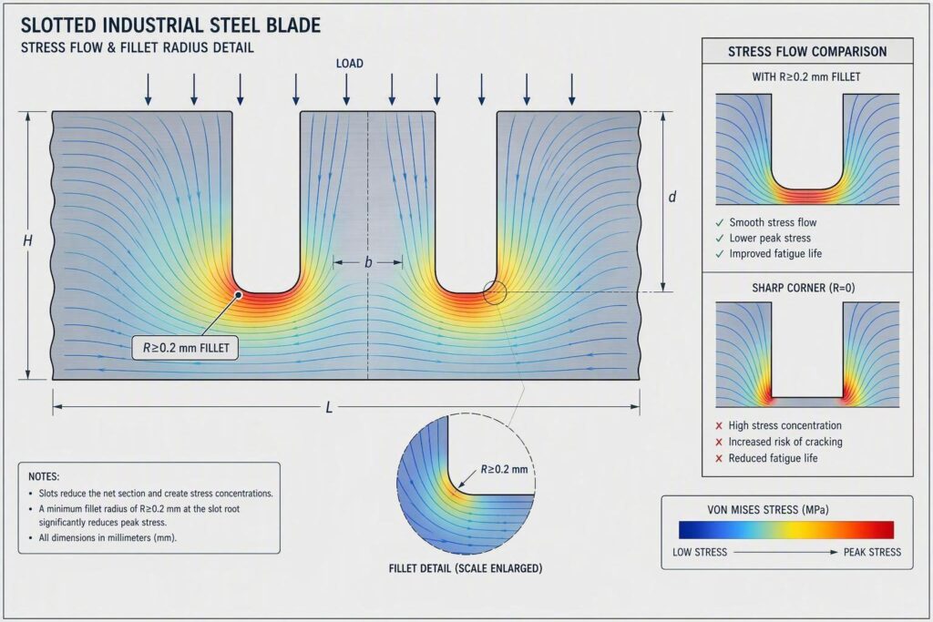
クイックサマリー: スリット溝底におけるグリッド刃(スリット刃)の折損は、3つの要因の相乗効果によって引き起こされます。それは、鋭角スリットによる高い弾性応力集中(Kt 7〜12)、クラックの発生源となる表面欠陥(EDM放電変質層や研削やけど)、および基材の靭性(高靱性)不足です。主要な工学的対策としては、溝底R半径をR≥0.2 mmに規定すること(これによりR0.05 mm形状と比較して応力集中係数Ktが約半分に低減します)、セカンドカット(スキンカット)や研磨によるEDM変質層(白层)の完全除去、および鋼種に応じた適切な2回焼き戻し(ダブル・テンパー)熱処理管理を組み合わせることが挙げられます。硬度HRC 56〜58のダイサー用スリット刃の適用事例では、溝底RをR0.20 mmに管理することで、突発的な刃物交換を約55〜65%削減し、計画外の設備停止時間を約45〜55%削減することに成功しました。
グリッドスリット刃の折損は、高速スリット切断およびグリッドカット工程において、最も生産を阻害し、かつ原因が误解されやすいトラブル(失效形式)の一つです。刃物がスリットの溝底で破断すると、計画外の設備停止、初回合格率(FPY)の低下、そしてコイル条材に対する二次的な structural/quality 不具合の波及といった致命的な影響が即座に発生します。連続コイル加工ラインを統括する製造マネージャーや方々にとって、たった1回の刃物折損事故が数時間に及ぶ修繕出戻り作業を引き起こし、月間の利益率を圧迫するスクラップ(歩留まり悪化)損害を発生させます。
その根本原因は、設計段階で組み込まれた応力集中、あるいは検出されなかった工程上の欠陥(加工欠陥)であるケースがほとんどです。スリット(溝)付き刃物において、溝底は刃物本体の中で最も高い応力が加わる部位となります。適切な幾何学形状の管理と金属組織の十分な靭性が確保されていない場合、遅かれ早かれ破断(クラック)が発生することになります。
解決策は二条の工学(エンジニアリング)戦略にあります。第一に、スリットR部(溝底)の応力集中係数(Kt)を確実に低減させるため、溝底R半径をR≥0.2 mmに規定し検証すること。第二に、そのR形状周辺の基材靭性を最大限に高めるため、精密に調整された2回焼き戻し(ダブル・テンパー)熱処理を適用することです。これら両戦略を支えるのが、工具・刃物の we Procurement(調達)時に見落とされがちな3つの工程管理です。それは、EDM放電変質層の完全除去、厳格な研削やけど(研削熱損傷)の防止、 processing 最終検査前の残留応力除去(ストレスリリーフ)の徹底です。
技術ノート: If your specification for slotted grid blades requires documented fillet radius verification, EDM process records, and heat-treat batch traceability, see Maxtor Metal’s reference page on 面取り加工された工業用ブレード用鋼帯(リール入り) for supply specifications and documentation standards applicable to precision slotted blade geometries.
本記事では、この二条の戦略の各要素を順次解説します。溝底における破断の機構(メカニズム)、溝底R形状が応力集中係数(Kt)を定量的に低減させる仕組み、ワイヤ放電加工(EDM)および研削加工における品質管理基準、鋼種に応じた焼き戻し(テンパー)条件の選定方法、そして刃物が実稼働に入る前の最終検証チェックポイントについて網羅します。
なぜスリット溝底はグリッド刃(網目状切断刃)が最も折損しやすい部位なのか
Stress Concentration at Slot Bottoms
In a slotted blade under bending or cyclic cutting loads, stress is not distributed uniformly across the cross-section. It concentrates sharply at geometric discontinuities — and no feature on a slotted blade creates a sharper discontinuity than a tight slot root.
The theoretical stress concentration factor Kt relates the peak local stress σ max to the nominal applied stress σ nom:
Kt = σ max / σ nom
For a rectangular slot in a finite plate, Kt is strongly influenced by the ratio of the root radius r to the slot half-width b (or depth t, depending on the reference model). When r approaches zero — as it does with a square-cornered slot — Kt climbs toward singularity. Even at r = 0.05 mm, Kt values of 8–12 are common in tight-slot geometries at industrial blade scales. At those multipliers, a nominal bending stress of 300 MPa becomes a local stress exceeding 2,400 MPa — well above the fracture toughness threshold for most high-carbon tool steels in the hardened-and-lightly-tempered condition.
The slot bottom is therefore not just a stress concentration — it is the single most failure-critical feature in the tool design. Every process decision downstream of design — EDM strategy, grinding pass depth, tempering protocol, final inspection — must be evaluated in the context of what it does to that slot root.
Crack Initiation Sources in Slots
Even with adequate fillet geometry, cracks can initiate at slot bottoms when surface or subsurface defects provide nucleation sites. The three most consequential defect sources in slotted blade manufacture are:
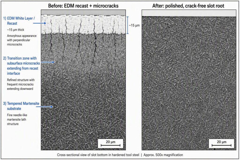
1. EDM recast (white) layer. Wire-EDM and sinker-EDM are standard processes for producing slots in hardened or semi-hardened tool steel. Both leave a resolidified, amorphous surface layer typically 2–25 µm thick. This layer is harder and more brittle than the base matrix — Vickers hardness values above 1,100 HV are common — and it contains tensile residual stresses and microcracks from the rapid resolidification thermal cycle. These microcracks are structural initiators under cyclic load. If left in place, they can propagate into the substrate within the first few thousand blade strokes.
2. Grinding-induced microcracks. Aggressive grinding after EDM — particularly with insufficient coolant delivery or excessive wheel speed — generates localized heat that causes surface temper, re-hardening, or micro-cracking. In the slot root geometry, where wheel access is restricted, coolant starvation is a persistent process risk.
3. Quench-induced residual tensile stress. During hardening, differential thermal contraction between the blade surface and core — particularly in the thin-wall regions around slots — generates residual tensile stresses. Without adequate stress-relief tempering, these stresses add directly to applied service stresses, reducing the effective fracture margin.
Role of Residual Tensile Stress
Residual stress is invisible to the inspector who uses only a hardness tester and a visual check. But it is fully additive to applied stress in the fracture-mechanics sense. A slot bottom carrying 150 MPa of residual tensile stress from quench shrinkage, combined with a 300 MPa applied bending stress and a Kt of 6, experiences a local stress state of approximately:
σ local ≈ Kt × (σ applied + σ residual) = 6 × 450 MPa = 2,700 MPa
Most high-alloy tool steels in service condition have plane-strain fracture toughness (KIC) between 20 and 35 MPa·m⁰·⁵ — but the range is wide because it spans different grades and heat-treat states.
For reference: D2 (1.2379) at HRC 58–62 typically shows KIC of 18–22 MPa·m⁰·⁵; M2 (1.3343) at HRC 62–65 is typically 20–25 MPa·m⁰·⁵; H13 (1.2344) at HRC 44–50 (lower hardness, higher toughness application) can reach 28–38 MPa·m⁰·⁵. When selecting a blade grade for a slotted geometry application, the KIC value at the intended service hardness — not an average range — is the relevant design input.
溝底R(フィレット半径)の構造設計
Why R≥0.2 mm Reduces Kt
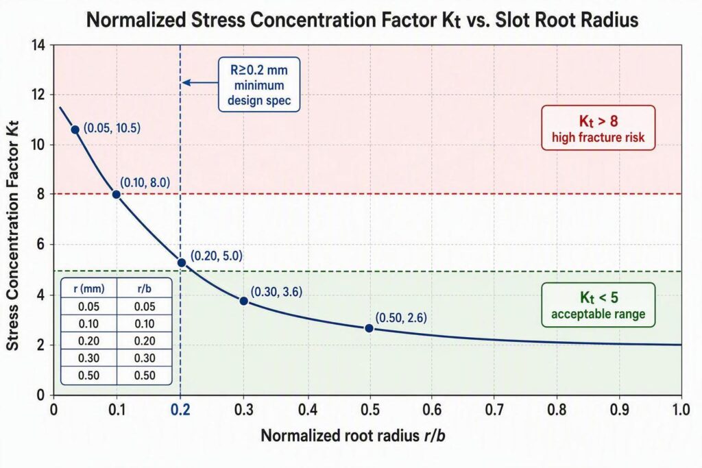
The relationship between fillet radius and Kt is nonlinear: the benefit is largest in the lower radius range, meaning the transition from R0.05 mm to R0.2 mm delivers a larger Kt reduction than the transition from R0.5 mm to R1.0 mm.
Using normalized stress concentration charts from Pilkey & Pilkey, Peterson’s Stress Concentration Factors (3rd ed., Wiley, 2008) for a slot in a finite-width plate under in-plane loading:
| Slot Root Radius r (mm) | Approximate Kt (typical slot geometry) |
|---|---|
| 0.05 | 10–12 |
| 0.10 | 7–8 |
| 0.20 | 4.5–5.5 |
| 0.30 | 3.5–4.0 |
| 0.50 | 2.5–3.0 |
The move from R0.05 mm to R0.20 mm cuts Kt roughly in half. If the material’s fracture resistance is held constant, halving Kt more than doubles the load-carrying capacity before crack initiation. Alternatively, at equivalent loads, halving Kt can extend fatigue life by an order of magnitude or more, depending on the fatigue crack growth exponent for the specific steel grade.
R0.2 mm is therefore a practical engineering minimum, not an arbitrary specification. It is the radius below which Kt rises sharply enough that even modest process variation — residual stress, surface defects, minor EDM recast remnants — pushes the slot bottom into reliable fracture territory.
Selecting Radius and Tolerances
Selecting the target radius requires balancing three competing constraints:
- Stress concentration reduction — a larger r is always mechanically beneficial.
- Slot dimensional function — the slot must still guide the strip or lock the grid pattern correctly. A root that is too large can interfere with a mating feature or alter the spring rate of thin blade webs.
- Manufacturability — the radius must be achievable and measurable by the processes in use (EDM skim cut, grinding, polishing).
For most industrial grid blade geometries, a target of R0.20 ± 0.05 mm is achievable with wire-EDM skim cuts followed by stone polishing, and is tight enough to maintain slot function while achieving the required Kt reduction. In thicker blades with deeper slots, R0.30–0.50 mm may be practical and should be evaluated where slot function permits.
Specify the tolerance unilaterally on engineering drawings: the minimum radius is the structural requirement; the maximum is a fit/function constraint. A notation of R0.20 min / R0.30 max makes this explicit and avoids the common shop-floor ambiguity of “rounding out the corner” without a defined upper limit.
Measuring and Verifying Radii
Slot root radii in the R0.2–R0.5 mm range require instrument-grade measurement. Acceptable methods include:
- Optical profilometry (non-contact): Resolves radii to ±0.005 mm; suitable for 100% inspection of critical slots.
- Radius gauge / ball gauge comparison: Adequate for in-process go/no-go at ±0.05 mm tolerance; fast and low-cost for line use.
- Coordinate measuring machine (CMM) with small-radius probe: ±0.003 mm achievable; recommended for first-article and PPAP documentation.
- Scanning electron microscopy (SEM) cross-section: Used for root-cause failure investigation, not routine inspection.
All measurement data must be recorded against the slot ID and correlated to the heat-treat lot. Radius measurement is a first-article requirement on any new tool geometry and a periodic in-process check during production.
EDM(ワイヤ放電加工)変質層と研削加工面の健全性(Surface Integrity)
EDM Recast Layer and Microcracks
Wire-EDM and sinker-EDM both produce a recast (white) layer that is metallurgically distinct from the underlying steel matrix. The recast layer:
- Is amorphous or fine-grained resolidified material with elevated carbon content.
- Has Vickers hardness typically 950–1,200 HV — harder and more brittle than the tempered martensite below it.
- Contains tensile residual stresses up to 600–1,000 MPa in severe cases.
- Harbors shallow microcracks (depth 1–20 µm) oriented perpendicular to the machined surface.
These microcracks are structurally equivalent to pre-existing flaws in a fracture-mechanics model. At slot bottoms, where applied and residual stresses are already at maximum, even a 5 µm crack can be sufficient to initiate propagation at service loads. Leaving the recast layer in place at slot roots is a latent reliability defect — regardless of how tightly the fillet radius is held.
The thickness of the recast layer is controlled primarily by EDM energy parameters (peak current, pulse duration, open-circuit voltage) and dielectric flushing conditions. Rough-cut passes typically leave 15–25 µm; fine-cut passes leave 3–8 µm. The goal of a well-designed EDM strategy is to minimize recast thickness on the final pass and then remove what remains by mechanical means.
Skim Cuts and Post-EDM Polishing
The standard process for recast removal at slot bottoms is a two-stage approach:
Stage 1 — EDM skim cuts. After the rough-cut slot form is established, perform one or two additional EDM passes at reduced energy (lower peak current, longer pulse-off time). These skim cuts remove the recast layer from the previous pass, replacing it with a thinner layer typically below 3 µm. The fillet radius is refined in the final skim pass to approach the target R≥0.2 mm.
Stage 2 — Mechanical polishing. Post-EDM polishing at the slot root using fine-grit abrasive stones (600–1,200 grit) or flexible abrasive tools removes the residual skim-cut recast layer and introduces compressive surface stress. Polishing depth of 5–10 µm is typically sufficient. The polished surface should show tempered martensite structure under metallographic examination at 500×, with no visible white layer remaining.
Nital etch (2–4% nitric acid in ethanol) on a representative cross-section is the standard checkpoint: recast appears as an unetched white band, which must be absent at the slot root in production-released blades. For critical slots, the etch check should be performed on a first-article coupon machined from the same lot and EDM program as production blades.
Grinding Burn Detection and Control
Post-EDM grinding — whether to correct fillet form or to finish adjacent surfaces — carries a risk of thermal damage at the slot root. Grinding burn causes:
- Surface softening (over-tempering) in the most common low-heat case.
- Re-hardening (formation of untempered martensite) in severe heat cases.
- Reversal of residual stress to tensile, adding to the existing stress state.
- Micro-cracking in the re-hardened zone.
All of these conditions reduce fracture resistance. The slot bottom is especially vulnerable because coolant access is restricted by slot geometry, and high-alloy tool steel’s lower thermal diffusivity means heat dissipation into the bulk is slower than in carbide or HSS.
Grinding burn controls for slot operations include:
- Reduced depth of cut: ≤0.005 mm per pass for finishing passes near slot roots.
- Flood coolant delivery at the tool-work interface, not general-area flooding.
- Friable abrasive wheel grades (e.g., seeded-gel alumina) that release worn grains before heat buildup.
- Acoustic emission or spindle-power monitoring as real-time thermal load indicators.
Nital etch per ISO 14104 (surface temper etch inspection after grinding) is the industry-standard acceptance method for burn detection, applied on first-article and periodic production coupons. Barkhausen noise analysis provides a quantitative, non-destructive production gate for any lot that required post-EDM grinding near slot roots.
高靭性を引き出す焼き戻し(テンパー)热处理
Double Tempering Parameters by Steel Grade
High-carbon, high-chromium cold-work tool steels used in slotted grid blades — including D2 (equivalent to JIS G4404 SKD11, DIN EN ISO 4957 grade 1.2379, ASTM A681 Grade D2), H13, and ledeburitic grades such as M2 — require a structured double-temper protocol to achieve the toughness required at slot bottoms. Single-temper cycles are insufficient for two reasons: they do not fully decompose retained austenite, and they leave secondary martensite (formed from that retained austenite during cool-down) in an untempered, brittle state.
Double tempering protocol by grade:
| 鋼種 | First Temper | Soak Time | Second Temper | Soak Time | Target HRC |
|---|---|---|---|---|---|
| D2 / 1.2379 / SKD11 | 180–200 °C | 2 h | 180–200 °C | 2 h | 58~62 |
| M2 / 1.3343 | 540–560 °C | 2 h | 540–560 °C | 2 h | 62–65 |
| D3 / 1.2080 | 200–220 °C | 2 h | 200–220 °C | 2 h | 60–63 |
| 8% Cr steels (1.2379 mod.) | 190–210 °C | 2 h | 190–210 °C | 2 h | 59–62 |
The first temper tempers as-quenched martensite and drives partial decomposition of retained austenite into secondary martensite. The second temper then tempers that secondary martensite. Air cooling between tempers to below 50 °C is required to allow the retained-austenite transformation to complete before the second soak begins.
Temperature uniformity within the furnace load is critical: a ±5 °C gradient is the accepted maximum for tool steel tempering. Loads that exceed this produce hardness variation exceeding ±1 HRC within the lot — which translates directly to variation in slot-bottom fracture toughness.
Managing Retained Austenite and Cryo
For D2-type steels austenitized at the upper end of the recommended range (1,030–1,060 °C) to achieve higher dissolution of primary eutectic carbides (M₇C₃) and better wear resistance, retained austenite (RA) content after quench can reach 15–25 vol%. At these RA levels, double tempering alone may not reduce RA to the ≤5 vol% target for high-toughness applications at stress concentrations.
Cryogenic treatment — cooling to −75 °C (dry ice/solvent) or −196 °C (liquid nitrogen), inserted between quench and first temper — drives additional RA transformation before the martensite is tempered. The result is reduced RA (typically to <3 vol% after cryo + double temper), more homogeneous hardness, improved dimensional stability, and measurably better toughness at stress-concentrated features. Cryo is recommended for D2-type slotted blades austenitized above 1,040 °C when XRD measurements indicate >10 vol% RA after quench.
For a detailed framework on how retained austenite control — including XRD-based verification per ASTM E975 and the heat-treatment window for 440C-class blade strip steel — is specified and documented in a supplier qualification program, see HRC 56~58での440Cダイサー交換用ブレードの検証.
At Maxtor Metal, double-temper cycles are executed under SPC control with continuous furnace temperature data logging. Each production lot is charted against ±5 °C control limits for both soak temperature and time-at-temperature. Barkhausen noise screening is applied at the slot-root inspection zone as a post-temper release gate — catching any lot in which a temperature excursion or retained-austenite anomaly has shifted the subsurface stress state out of specification before that lot reaches assembly. This documented process architecture is what separates a blade built to engineering specification from one built to approximate practice.
溝底根元(スロットルート)のR形状精度および金属組織(金相)が規格内にあることを検証する方法
Metallography and Nital Etch Checkpoints
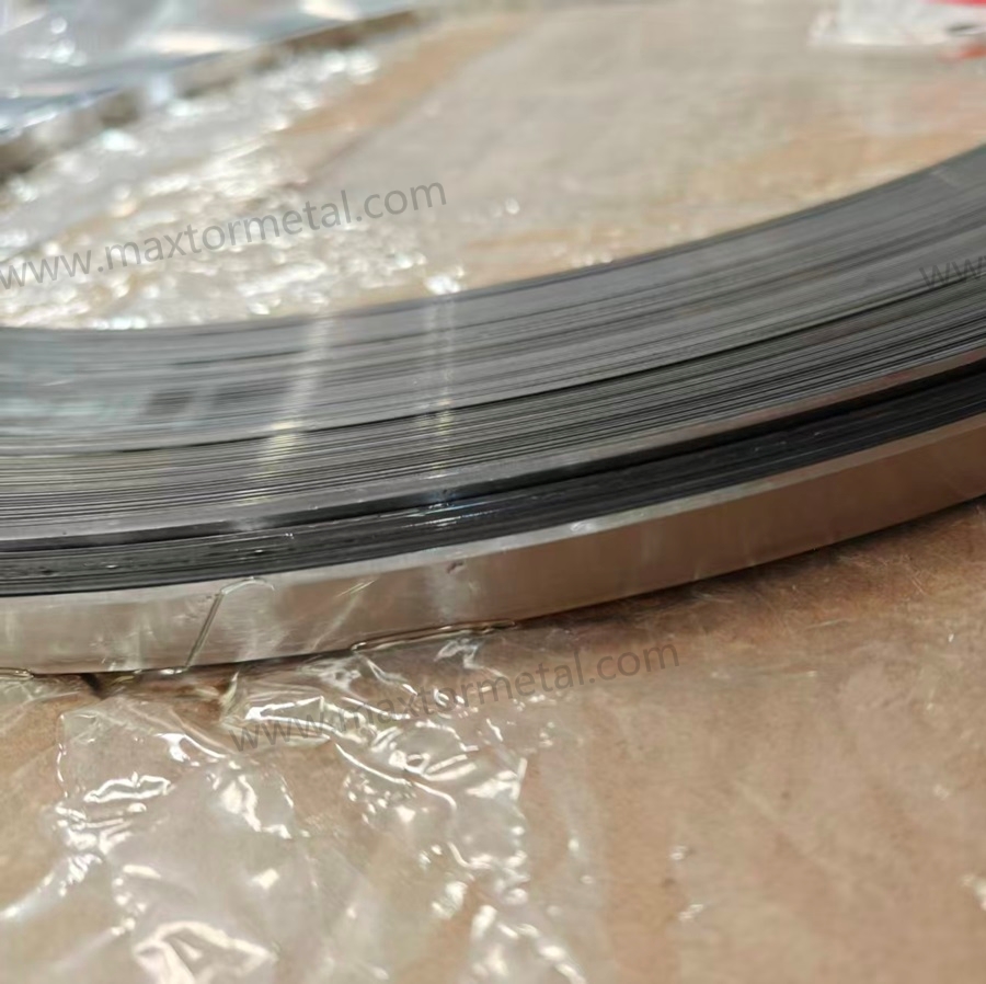
Metallographic cross-sectioning at slot root locations is the ground-truth verification method. First-article and periodic production coupons are prepared as follows:
- Sectioning: Transverse cut through the slot root at mid-length.
- Mounting and polishing: Standard metallographic preparation to 0.05 µm alumina finish.
- Nital etch (2–4%): Reveals martensitic structure, recast white layer, grinding burn zones, and carbide distribution.
- Examination at 200×, 500×, 1,000×: Check for zero recast white layer at the slot root, tempered martensite morphology consistent with the target HRC range, uniform primary carbide distribution with no grain-boundary clustering, and no micro-cracks in the root zone.
Retained austenite quantification by X-ray diffraction (XRD) — per ASTM E975 — is performed on first-article and after any hardening process change. Production release target: ≤5 vol%.
For the incoming material verification side of this traceability chain — reading tool steel MTCs, verifying chemistry acceptance bands by grade, and linking heat numbers to coil tags — see Reading Tool Steel MTC for Strip Blades: A Practical QA Checklist.
Barkhausen and Dye Penetrant Screens
Barkhausen noise analysis (BNA) is a non-destructive magnetic method sensitive to near-surface residual stress and microstructure in ferromagnetic steels. At slot bottoms, BNA detects tensile residual stress elevation (reduced emission amplitude relative to a reference), grinding burn (altered martensite morphology shifts emission spectrum), and subsurface re-hardening zones not visible on the polished surface.
BNA probes are miniaturized to fit slot access geometry. Calibration is performed against a reference set of coupons with known residual stress states confirmed by XRD. Production accept/reject criteria are expressed as Barkhausen amplitude relative to a calibrated baseline: deviations >±15% trigger hold-and-investigate. SAE ARP4462 (Barkhausen Noise Inspection for Detecting Grinding Burns in High Strength Steel Parts) provides a recognized calibration and acceptance framework.
Dye penetrant inspection (DPI) — per ASTM E165 / ISO 3452 — is applied after final polishing and before coating or assembly. DPI is sensitive to surface-open cracks ≥1 µm in width and provides 100% production coverage where sectioning is destructive. Any indication in the slot root zone is cause for rejection.
PPAP-Style Documentation and Metrics
A PPAP-adapted control framework for tooling blades establishes the control plan, measurement system validation (MSA), and production metrics required to sustain slot-root quality:
| Document / Record | Content | 頻度 |
|---|---|---|
| First-article inspection report (FAIR) | CMM radius, hardness traverse, metallography, XRD RA, BNA baseline | Per new tool geometry |
| Control plan | Process parameters and in-process checks for EDM, grinding, tempering | Per blade family |
| SPC charts | Tempering temperature, fillet radius, hardness, BNA amplitude | Per production lot |
| Nital etch record | Photomicrograph archive of slot root cross-section, signed and dated | Per lot (coupon sample) |
| DPI log | Pass/fail per blade serial or lot | 100% production |
| Corrective action log | NCR linkage, root cause, and response action | Per rejection event |
SPC control limits for slot root radius are set at ±0.03 mm around nominal (e.g., 0.20–0.26 mm for an R0.23 mm nominal target). Process capability index Cpk ≥ 1.33 is the production release criterion. Lots falling below Cpk 1.33 on radius or hardness are placed on hold pending engineering review.
匿名化顧客導入事例:ダイサー(サイコロ状切断機)用スリット刃の溝底折損トラブル改善案
The following case comes from a real dicer-blade failure investigation, shared anonymously with the customer’s consent. Identifying details — the processor’s identity, the machine brand, and the exact production line — are withheld at the customer’s request, and the before/after figures have been rounded and normalized to protect commercially sensitive production data. Even so, the mechanism, measurement sequence, and outcome all come from what actually happened on this line, and they show how the principles above play out when slot-root geometry is the dominant cause of grid blade snapping.
Production Scenario
An anonymous poultry processor on a high-throughput food-cutting line experienced repeated failures of its dicer grid/crosscut strip blades. The machine was a commercial rotary dicer of the ~3,000 kg/h class, processing frozen-tempered chicken for further food manufacturing. Typical machines in this class support poultry dicing across roughly 4.8–76 mm, depending on product thickness, feeding method, and machine condition.
This application ran at approximately:
- Product: frozen-tempered chicken
- Dice size: approximately 10–20 mm
- Blade material: 440Cステンレス鋼
- Target hardness: HRC 56–58
- Blade thickness: approximately 1.5–2.0 mm
- Production: multiple shifts per day
- Failure mode under investigation: grid blade snapping at the bottom of the locating slots
The critical detail is that the blade rarely failed because the cutting edge had worn out. The disruptive failure was a sudden fracture through the strip at a slot bottom — the same failure mode discussed throughout this article.
Original Blade Failure
The original grid blade used a relatively sharp slot-bottom transition, with nominal drawing geometry of approximately R0–0.10 mm. Because the broken blades appeared brittle, the maintenance team initially assumed a material or hardness problem.
During an initial failure review covering the documented fracture events recorded over the investigation period, approximately 70–85% of confirmed fractures were found to initiate in or immediately adjacent to the slot-bottom transition. (The exact sample count is withheld at the customer’s request; the percentage range reflects the bounds of the observed distribution across multiple documentation records.)
The typical sequence was:
- slot-bottom damage → small crack → cyclic crack growth → sudden blade fracture
The cutting edge itself could still appear serviceable immediately before failure. A dicer knife operates under repeated mechanical loading rather than a single static load, so a small geometric discontinuity readily becomes a fatigue initiation site — consistent with the general engineering guidance to use the largest practical fillet radius the functional geometry permits.
First Attempt: Reducing Hardness
Before touching geometry, the processor tried lowering the blade hardness from approximately HRC 58–60 to HRC 55–57, leaving the slot geometry unchanged.
The result reduced catastrophic snapping only slightly, while creating a new problem: edge wear increased, cut quality deteriorated earlier, sharpening/replacement frequency rose, and slot-bottom cracking was still observed. The attempt demonstrated an important principle — reducing hardness can change the failure response without eliminating the stress concentration that initiates the crack. The team therefore returned to the HRC 56–58 target and investigated the geometry.
Measurement Sequence
Step 1 — Map the fracture locations. Every failed grid blade was tagged by machine position, blade orientation, slot number, production hours, product condition, and fracture location. The purpose was to test whether fractures were random. They were not — the same slot-bottom geometry appeared repeatedly in the failure records.
Step 2 — Inspect the slot-bottom radius. Representative blades were checked with an optical comparator or toolmaker’s microscope. Measured radii were approximately R0.05–0.12 mm rather than a consistent larger radius, and some slot bottoms showed localized grinding marks. This matters because a drawing dimension alone does not describe the fatigue condition of a small radius: a nominal R0.10 mm radius with a grinding notch behaves differently from a smooth R0.10 mm radius.
Step 3 — Inspect the fracture origin. Broken blades were examined at low magnification for crack initiation location, grinding marks, local notches, impact evidence, deformation around the slot, and material defects. The recurring finding was that the fracture path tracked the slot-bottom transition rather than occurring randomly through the cutting edge — making a geometry change more logical than further hardness adjustment.
Geometry Modification
The trial retained 440C stainless steel at HRC 56–58. The primary design change was the slot-bottom radius:
- Slot-bottom radius: R0–0.10 mm → controlled R0.20 mm
The objective was not to make the radius “as large as possible” in isolation. The team used the largest radius that could be accommodated without interfering with blade engagement, adjacent components, grid spacing, product clearance, mounting geometry, or required dice dimensions. R0.20 mm should therefore be read as the design target for this application, not a universal dicer specification. The underlying rule is better stated as: use the largest practical slot-bottom radius that the blade geometry and machine clearance allow — consistent with the general principle that increasing a fillet radius reduces local stress concentration wherever geometry permits.
Grinding Process Control
The radius change alone was not considered sufficient. Grinding was standardized to avoid creating a new notch inside the radius. The inspection checklist included:
- Verify slot width
- Verify slot-bottom radius
- Check for visible grinding grooves
- Check for local undercutting
- Inspect the transition between slot wall and bottom
- Verify blade thickness
- Verify hardness on the qualification batch
- Inspect the first production run after installation
This reinforces a point made earlier: a nominal R0.20 mm radius is not automatically fatigue-resistant if the manufacturing process leaves a sharp grinding groove inside the radius.
For the regrind lifecycle framework that governs how many re-sharpenings a blade can sustain before slot-bottom geometry becomes a disqualifying factor, see 産業用ストリップナイフの再研磨:研削・再研磨の閾値、破棄(スクラップ)基準、およびライフサイクルコストモデル.
Customer Case Results
Rounded, normalized figures from this customer’s production records:
| メトリック | オリジナルデザイン | R0.20 mm blades |
|---|---|---|
| 材料 | 440C | 440C |
| 硬度 | HRC 56–58 | HRC 56–58 |
| Slot-bottom radius | R0–0.10 mm | R0.20 mm |
| Typical blade life | 70–100 h | 150–190 h |
| Premature snapping | ベースライン | ↓ approximately 55–65% |
| Emergency grid changes | ベースライン | ↓ approximately 50–60% |
| 予期せぬダウンタイム | ベースライン | ↓ approximately 45–55% |
| Slot-bottom cracks during the trial period | Recurrent | None observed |
The most important observation was not the increase in average life — it was the change in failure mode. Before the modification, the maintenance team frequently had to respond to an unexpected broken grid blade. Afterward, routine wear and planned replacement became more significant than sudden slot-bottom fracture.
If your failure log shows that emergency grid-blade changes — rather than scheduled replacements — are the primary contributor to line downtime, the OEE model in コイル交換頻度の削減によるOEEと利益の向上 provides a quantified framework for converting unplanned downtime reduction into a measurable OEE gain.
Example Downtime Calculation
At the customer’s baseline, the line logged approximately 6 emergency grid-blade failures per 1,000 operating hours, each requiring roughly 20–30 minutes of unplanned intervention. Using the 25-minute midpoint:
- 6 × 25 min = 150 min / 1,000 h
With emergency events down by approximately 55% after the change:
- 6 × (1 − 0.55) ≈ 2.7 events → 2.7 × 25 min ≈ 68 min / 1,000 h
The resulting saving was roughly 82 minutes of unplanned downtime per 1,000 operating hours. This is a normalized projection from the customer’s own baseline and post-change records; individual lines will vary with product mix and operating discipline.
Operator Behavior
The investigation also surfaced a human factor. In the early stage, operators sometimes kept running the machine after noticing an unusual sound or a small crack during inspection, risking a small fatigue crack growing into a complete break. The revised procedure introduced a simple rule: any visible crack at the slot bottom = remove and quarantine the blade. Operators were also instructed to inspect slot bottoms, blade seating, abnormal contact marks, product buildup, and evidence of impact. This is another reason the improvement should not be attributed to the R0.20 mm radius alone.
Process Limitations
The result should be interpreted within its operating window. It is most applicable to 440C dicer grid/crosscut strip blades at HRC 56–58, cutting frozen-tempered poultry, with controlled blade installation, normal production loading, and no significant metal contamination or abnormal impact. It should not be read as evidence that R0.20 mm is optimal for every dicer blade. A different blade thickness, slot width, dice size, material, heat treatment, machine, product temperature, or mounting method could require a different radius — cutting capacity and results depend on product condition, feeding method, machine condition, and knife configuration.
Case Conclusion
This anonymized frozen-tempered poultry dicing investigation identified repeated grid-blade fractures at the bottom of locating slots. The original slot geometry used a relatively sharp R0–0.10 mm transition, and replacement blades were made from 440C stainless steel at approximately HRC 56–58. An initial attempt to reduce hardness did not eliminate the problem and increased edge wear.
The subsequent work retained the HRC 56–58 material condition but increased the slot-bottom radius to a controlled R0.20 mm and tightened control of grinding damage and blade inspection. On this customer’s line, typical blade life increased from approximately 70–100 operating hours to 150–190 hours. Emergency grid-blade changes fell by approximately 50–60%, while unplanned downtime associated with blade snapping fell by approximately 45–55%. No slot-bottom cracks were observed during the follow-up period.
The result should not be interpreted as a universal “R0.20 mm doubles blade life” rule. The improvement came from controlling slot geometry together with grinding quality, blade hardness, installation, and operator inspection. The practical design rule is to use the largest slot-bottom radius that the dicer geometry and clearance allow, while avoiding grinding notches or undercuts at the radius transition.
よくあるご質問
Q: グリッド刃(スリット刃)の折損を防ぐための最小溝底R半径(フィレット半径)はいくらですか?
A: ほとんどのスリット付き底溝型刀片形状において、実用上の工学最小値は R0.2 mm です。この値を下回ると、応力集中係数 Kt が 7〜12 という高い数値へ急激に跳ね上がり、残留応力や表面粗さ(加工面粗度)の工程ばらつきと相まって、スリット根元(溝底)からの脆性破断(Brittle fracture)を引き起こす条件が定常的に形成されてしまいます。より大きなR半径(R0.3〜0.5 mm)はさらなる安全マージンをもたらすため、溝の機能が許す限り検討・適用すべきです。
Q: なぜスリット付きの刃物(溝付き刀片)は、刃先(刃先線)ではなく溝底から破断するのですか?
A: 溝底には、曲げ荷重や繰返し荷重(変動荷重)がかかった際、公称応力の数倍に達する弾性応力が集中します。刃先も接触応力を受けますが、実働時は圧縮方向の接触形状となるため破断に対しては有利に働きます。一方、スリット根元(溝底)は幾何学的な応力集中部(応力集中源)であり、ワイヤ放電加工(EDM)や高周波・真空淬火(焼き入れ)による残留引張応力も蓄積されやすいため、最も破断(クラック)が発生しやすい起点となります。
Q: 放電加工(EDM)の再凝固層(白層)は、なぜ工具鋼ブレードのクラック(亀裂)を引き起こすのですか?
A: EDM再凝固層(ホワイトレイヤー)は、母材のマルトンサイト組織(マルテンサイト)よりも硬く(通常 950〜1,200 HV)、急冷固化プロセスに起因する残留引張応力と浅いマイクロクラック(微細亀裂)を含んだ非晶質(アモルファス)層です。破壊力学の観点において、これらの微細亀裂は「初期欠陥」として機能します。応力が集中するスリット根元(溝底)で繰返し荷重(変動荷重)を受けると、この亀裂が基材内部へと進展し、刀片の実働初期段階で急速破断(早期折損)を引き起こす原因となります。実稼働投入前にこの層の除去(エッチングや研削)が必須となります。
Q: ダブルテンパー(2回焼き戻し)とは何ですか?なぜスリット付き(溝付き)工具鋼ブレードに必要なのですか?
A: ダブルテンパーとは、2回の完全な焼き戻しサイクル(保持+室温まで空冷+再保持)を行う熱処理工程です。1回目のサイクルで淬火(焼き入れ)直後のマルテンサイトを焼き戻し、残留オーステナイトの一部を二次マルテンサイトへ分解させます。2回目のサイクルでその二次マルテンサイトを焼き戻します。1回のみの焼き戻し(シングルテンパー)では、二次マルテンサイトが未焼き戻しのまま非常に脆い状態で残り、溝底のような応力集中部において致命的な脆化欠陥となります。ASTM A681 D2 や JIS G4404 SKD11 などの規格において、靭性が要求されるスリット付き工具のダブルテンパーは標準仕様( mandatory practice )とされています。
Q: 標準プローブが入らないほど狭い溝の内部で、研削焼け(Grinding burn)を検出するにはどうすればよいですか?
A: 狭溝アクセス用に小型化(ミニチュア化)された専用プローブを用いたバルクハウゼンノイズ解析(BNA)が、最も感度の高い非破壊検査手法です。BNAは熱影響(熱損傷)、再焼き入れ(二次マルテンサイト生成)、または残留引張応力によって生じる表面近傍の磁気ドメイン(磁性体構造)の変化を捉えます。これらはすべて研削焼けの典型的なサインです。また、初回品(初物)や定期的な量産 split クーポン(金属組織試験片)に対し、ISO 14104 に準拠したナイタル腐食液(Nital etch)による金相組織観察(金属組織検査)を行うことで、破壊検査による最終的な確認・検証が可能です。
Q: D2鋼製スリット刃(溝付き刀片)の淬火(焼き入れ)後、許容される残留オーステナイト(Retained Austenite)の比率はどれくらいですか?
A: 淬火およびダブルテンパー(2回焼き戻し)後の出荷合格基準は、ASTM E975 に準拠した X線回折法(XRD)測定で残留オーステナイト(RA)体积分率 ≤5 vol% です。1,040 ℃以上でオーステナイト化されたD2系鋼材は、焼き入れ直後に 15〜25 vol% の残留オーステナイトを含有することがあります。RAが 10 vol% を超える場合、焼き戻し工程に入る前に−75 ℃〜−196 ℃での深冷処理(サブゼロ処理/クリオジェニック処理)を挟み、マルテンサイト変態を促進させることが推奨されます。
出荷前にスロットグリッドブレード(溝付き格子刃)に実施すべき非破壊検査(NDT)は何ですか?
完全な出荷前検査工程には以下が含まれる必要があります:研削焼けおよび残留応力異常を検出するためのスロットルート部におけるバルクハウゼンノイズ解析(BNA)、表面開口欠陥(クラック)を検出するためのASTM E165 / ISO 3452に準拠した浸透探傷試験(DPI)、および光学プロフィロメトリーまたはCMM(三次元測定機)によるR部(コーナー半径)の判定。ロックウェル硬度(HRC)測定は工程管理(process control)工程であり、上記の非破壊検査の代用にはなりません。DPIは刃物全体の100%をカバーし、BNAおよびR部測定はスロットルートの構造的健全性を保証する最重要品質ゲートです。
Maxtor Metalは、スロットゾーンごとのBNA振幅データ、刃物シリアルごとのDPI合否ログ、CMMまたはプロフィロメトリーによるR寸法測定報告書を含む完全なNDTドキュメントパッケージを、サプライヤー監査およびPPAPスタイルの承認に適した形式でお客様に提供します。
Q: 刃物製造工程において、スロットフレットR(溝のすみ肉コーナー半径)のSPC管理限界線はどのように設定しますか?
A: 機能公差幅の中央値に公称R(ノミナル値)を設定します。監視用管理限界は公称値の±0.03 mmに定義します。初物能力データ(初回品判定)からCpkを算出し、量産出荷合格基準としてCpk ≥ 1.33を要求します。測定誤差が工程ばらつきの推定量(推定分散)を膨らませないことを確認するため、SPC運用の開始前にゲージR&R(GR&R)研究を実施し、測定システム(光学プロフィロメトリーまたは三次元測定機/CMM)の妥当性を検証してください。
結論
スロット底面(溝底)における格子刃(グリッドブレード)の折損は、偶発的な破損モードではありません。応力集中、表面欠陥、および靭性不足が工具の同一箇所に共存することを許容した結果生じる、必然的な破壊現象です。
より大きなR部(隅肉コーナー半径 R≥0.2 mm)を確保することで、鋭角なコーナー形状と比較して応力集中係数 Kt を約50%低減し、スロットルート部のピーク応力を直接緩和して破断限界寿命を延長します。鋼種および残留オーステナイト量に合わせた最適条件でのダブルテンパー(2回焼き戻し)は、焼き入れ直後の脆い組織を靭性の高いマトリックスへと変容させ、刃物基部(ウェブ)でのクラック (亀裂) 進展を駆動する歪み能量を効果的に吸収します。
プロセス(加工工程)の健全性が維持されていなければ、形状設計や冶金的アプローチだけでは不十分です。EDM(放電加工)によって生じる改質層・変質層(リキャストレイヤー)は、仕上げカット(スキムカット)および研磨工程で機械的に完全除去する必要があります。スロットルート(溝底)付近の研削加工は、研削焼けを防ぐよう厳密に管理し、バルクハウゼンノイズ解析により評価・検証しなければなりません。残留応力は、適切な焼入れ速度の制御と歪み取り焼き戻し(ストレスリリーフ)によって管理すべきであり、硬度規格を満たしているからといって問題がないと見なしてはなりません。
最後の重要な要素は体系的な検証です。ナイタル腐食断面観察、バルクハウゼンノイズ(BNA)スクリーニング、浸透探傷試験(PT)、およびSPC管理された工程記録により、スロットRの寸法指示から出荷に至るまでのトレーサビリティある品質チェーンが構築されます。刃物製造プログラム全体で一貫してこれらの仕様と検査を標準化することで、刃物の信頼性は「使用中に判明する結果」から「初回使用前に設計・検証された確実な性能」へと進化します。
Maxtor Metal provides customers specifying precision slotted grid blades with batch-level documentation covering slot-root radius measurement records (CMM or optical profilometry), EDM skim-cut and nital etch verification, double-temper batch records with continuous furnace data logs, XRD-based retained austenite results, and Barkhausen noise screening reports at slot-root zones. Customers running formal supplier qualification programs can request the full documentation package before first shipment to validate that slot-root geometry and heat-treat parameters are controlled to engineering specification, not estimated from process experience.
著者について
ジェシー・シュー — 上級品質エンジニア、QA(品質保証)、Maxtor Metal
Jesse Xu is a Senior Quality Engineer with 15 years of experience in industrial blade manufacturing and quality assurance. His work focuses on failure analysis: determining whether blade failures such as edge chipping and premature wear originate from heat-treatment process deviations or from material segregation (carbide/banding) issues. He holds the ASQ Certified Quality Engineer (CQE) credential, is an ISO 9001 Lead Auditor, and is certified to ASNT NDT Level II.
免責事項・技術諮問お問い合わせ
This article is published by Maxtor Metal, a manufacturer and supplier of custom, precision-ground industrial blades. It is provided for technical education and product explanation; because it references Maxtor Metal products, readers should be aware of a potential commercial interest. Technical claims are referenced to publicly available standards (ISO, ASTM, SAE) and established engineering literature, and readers are encouraged to verify specifications against their own application requirements.
For questions about this article, blade design specifications, or technical support, please reach out via our お問い合わせページ.

 English
  Spanish
  Italian
  French
  Portuguese
  Russian
  German
  Arabic
  Hindi
Hindi  Vietnamese
  Indonesian
  Japanese
  Korean