

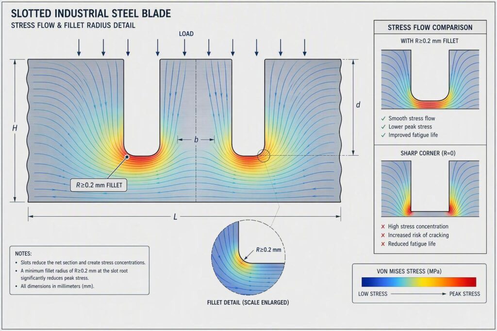
Kurzantwort: Das Brchen von Gittermessern am Nutgrund wird durch das Zusammenspiel dreier Faktoren verursacht: hohe elastische Spannungskonzentration (Kt 7–12 bei scharfkantigen Nuten), Oberflächenfehler als Rissinitiatoren (EDM-Umschmelzschichten, Schleifbrand) sowie unzureichende Zähigkeit des Werkstoffs. Die primäre konstruktive Abhilfe besteht in der Festlegung eines Nutgrundradius von R≥0,2 mm —wodurch der Kt-Wert gegenüber einer R0,05-mm-Geometrie etwa halbiert wird— kombiniert mit der vollständigen Entfernung der EDM-Umschmelzschicht durch Nachschnittpassagen (Skim Cuts) und Polieren sowie einem auf die jeweilige Stahlsorte abgestimmten Doppel-Anlassverfahren. In einem dokumentierten Kundenfall mit Würfelschneider-Gittermessern bei HRC 56–58 reduzierte die Einhaltung eines Nutgrundradius von R0,20 mm die ungeplanten Messeraustausche um ca. 55–65 % und die unplanmäßigen Ausfallzeiten um ca. 45–55 %.
Der Bruch von Gittermessern gehört zu den folgenschwersten und am häufigsten missverstandenen Ausfallursachen bei hochfrequenten Längsteil- (Slitting) und Gitterschneidprozessen. Wenn ein Messer am Nutgrund bricht, sind die Folgen sofort spürbar: ungeplante Stillstandszeiten, Einbußen bei der Erstausbeute (FPY) und eine Kaskade sekundärer Qualitätsprobleme am Band. Für Produktionsleiter und Anlagenspezialisten in kontinuierlichen Bandbearbeitungslinien kann ein einziger Messerbruch stundenlange Korrekturwartungen nach sich ziehen und Ausschusskosten verursachen, die die monatlichen Margen erheblich belasten.
Die Ursache liegt fast immer in einer konstruktiv bedingten Spannungskonzentration —oder einem unentdeckten Prozessfehler. Bei Nutenmessern ist der Nutgrund die Stelle mit der höchsten Spannungsbelastung im gesamten Messerkörper. Ohne präzise Geometriekontrolle und ausreichende gefügetechnische Zähigkeit ist das Auftreten eines Anrisses nur eine Frage der Zeit.
Die Lösung liegt in einer doppelten ingenieurtechnischen Strategie. Erstens: Festlegung und Überprüfung eines Nutgrundradius von R≥0,2 mm, um den elastischen Spannungskonzentrationsfaktor (Kt) am Nutgrund messbar zu reduzieren. Zweitens: Anwendung eines präzise abgestimmten Doppel-Anlassverfahrens bei der Wärmebehandlung, um die Zähigkeit des Werkstoffs im Bereich des Radius zu maximieren. Unterstützt werden beide Strategien durch drei Prozessdisziplinen, die beim Werkzeugeinkauf häufig übersehen werden: die vollständige Entfernung von EDM-Umschmelzschichten, das konsequente Vermeiden von Schleifbrand sowie das Entpannen von Eigenspannungen vor der Endkontrolle.
Technischer Hinweis: If your specification for slotted grid blades requires documented fillet radius verification, EDM process records, and heat-treat batch traceability, see Maxtor Metal’s reference page on Industrieller Klingenbandstahl in abgeschrägten Spulen for supply specifications and documentation standards applicable to precision slotted blade geometries.
Dieser Artikel erläutert nacheinander jedes Element dieser doppelten Strategie: die Bruchmechanik am Nutgrund, wie die Geometrie des Nutgrundradius den Kt-Faktor messbar reduziert, welche Qualitätsprüfungen bei der Drahterosion (EDM) und beim Schleifen erforderlich sind, wie die Anlassparameter nach Stahlgüte ausgewählt werden und welche Prüfpunkte den Qualitätskreis vor der Inbetriebnahme des Messers schließen.
Warum der Nutgrund immer die erste Stelle ist, an der ein Gittermesser bricht
Stress Concentration at Slot Bottoms
In a slotted blade under bending or cyclic cutting loads, stress is not distributed uniformly across the cross-section. It concentrates sharply at geometric discontinuities — and no feature on a slotted blade creates a sharper discontinuity than a tight slot root.
The theoretical stress concentration factor Kt relates the peak local stress σ max to the nominal applied stress σ nom:
Kt = σ max / σ nom
For a rectangular slot in a finite plate, Kt is strongly influenced by the ratio of the root radius R to the slot half-width B (or depth T, depending on the reference model). When R approaches zero — as it does with a square-cornered slot — Kt climbs toward singularity. Even at R = 0.05 mm, Kt values of 8–12 are common in tight-slot geometries at industrial blade scales. At those multipliers, a nominal bending stress of 300 MPa becomes a local stress exceeding 2,400 MPa — well above the fracture toughness threshold for most high-carbon tool steels in the hardened-and-lightly-tempered condition.
The slot bottom is therefore not just a stress concentration — it is the single most failure-critical feature in the tool design. Every process decision downstream of design — EDM strategy, grinding pass depth, tempering protocol, final inspection — must be evaluated in the context of what it does to that slot root.
Crack Initiation Sources in Slots
Even with adequate fillet geometry, cracks can initiate at slot bottoms when surface or subsurface defects provide nucleation sites. The three most consequential defect sources in slotted blade manufacture are:
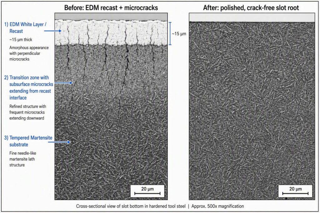
1. EDM recast (white) layer. Wire-EDM and sinker-EDM are standard processes for producing slots in hardened or semi-hardened tool steel. Both leave a resolidified, amorphous surface layer typically 2–25 µm thick. This layer is harder and more brittle than the base matrix — Vickers hardness values above 1,100 HV are common — and it contains tensile residual stresses and microcracks from the rapid resolidification thermal cycle. These microcracks are structural initiators under cyclic load. If left in place, they can propagate into the substrate within the first few thousand blade strokes.
2. Grinding-induced microcracks. Aggressive grinding after EDM — particularly with insufficient coolant delivery or excessive wheel speed — generates localized heat that causes surface temper, re-hardening, or micro-cracking. In the slot root geometry, where wheel access is restricted, coolant starvation is a persistent process risk.
3. Quench-induced residual tensile stress. During hardening, differential thermal contraction between the blade surface and core — particularly in the thin-wall regions around slots — generates residual tensile stresses. Without adequate stress-relief tempering, these stresses add directly to applied service stresses, reducing the effective fracture margin.
Role of Residual Tensile Stress
Residual stress is invisible to the inspector who uses only a hardness tester and a visual check. But it is fully additive to applied stress in the fracture-mechanics sense. A slot bottom carrying 150 MPa of residual tensile stress from quench shrinkage, combined with a 300 MPa applied bending stress and a Kt of 6, experiences a local stress state of approximately:
σ local ≈ Kt × (σ applied + σ residual) = 6 × 450 MPa = 2,700 MPa
Most high-alloy tool steels in service condition have plane-strain fracture toughness (KIC) between 20 and 35 MPa·m⁰·⁵ — but the range is wide because it spans different grades and heat-treat states.
For reference: D2 (1.2379) at HRC 58–62 typically shows KIC of 18–22 MPa·m⁰·⁵; M2 (1.3343) at HRC 62–65 is typically 20–25 MPa·m⁰·⁵; H13 (1.2344) at HRC 44–50 (lower hardness, higher toughness application) can reach 28–38 MPa·m⁰·⁵. When selecting a blade grade for a slotted geometry application, the KIC value at the intended service hardness — not an average range — is the relevant design input.
Konstruktion des Nutgrundradius (Eckenradius-Design)
Why R≥0.2 mm Reduces Kt
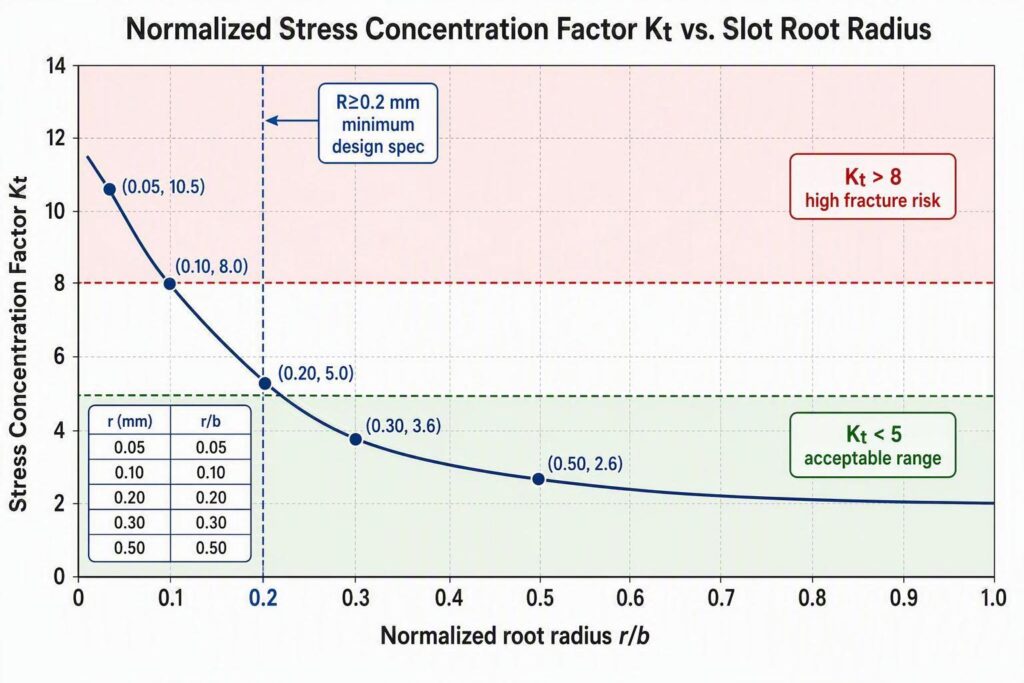
The relationship between fillet radius and Kt is nonlinear: the benefit is largest in the lower radius range, meaning the transition from R0.05 mm to R0.2 mm delivers a larger Kt reduction than the transition from R0.5 mm to R1.0 mm.
Using normalized stress concentration charts from Pilkey & Pilkey, Peterson’s Stress Concentration Factors (3rd ed., Wiley, 2008) for a slot in a finite-width plate under in-plane loading:
| Slot Root Radius r (mm) | Approximate Kt (typical slot geometry) |
|---|---|
| 0.05 | 10–12 |
| 0.10 | 7–8 |
| 0.20 | 4.5–5.5 |
| 0.30 | 3.5–4.0 |
| 0.50 | 2.5–3.0 |
The move from R0.05 mm to R0.20 mm cuts Kt roughly in half. If the material’s fracture resistance is held constant, halving Kt more than doubles the load-carrying capacity before crack initiation. Alternatively, at equivalent loads, halving Kt can extend fatigue life by an order of magnitude or more, depending on the fatigue crack growth exponent for the specific steel grade.
R0.2 mm is therefore a practical engineering minimum, not an arbitrary specification. It is the radius below which Kt rises sharply enough that even modest process variation — residual stress, surface defects, minor EDM recast remnants — pushes the slot bottom into reliable fracture territory.
Selecting Radius and Tolerances
Selecting the target radius requires balancing three competing constraints:
- Stress concentration reduction — a larger R is always mechanically beneficial.
- Slot dimensional function — the slot must still guide the strip or lock the grid pattern correctly. A root that is too large can interfere with a mating feature or alter the spring rate of thin blade webs.
- Manufacturability — the radius must be achievable and measurable by the processes in use (EDM skim cut, grinding, polishing).
For most industrial grid blade geometries, a target of R0.20 ± 0.05 mm is achievable with wire-EDM skim cuts followed by stone polishing, and is tight enough to maintain slot function while achieving the required Kt reduction. In thicker blades with deeper slots, R0.30–0.50 mm may be practical and should be evaluated where slot function permits.
Specify the tolerance unilaterally on engineering drawings: the minimum radius is the structural requirement; the maximum is a fit/function constraint. A notation of R0.20 min / R0.30 max makes this explicit and avoids the common shop-floor ambiguity of “rounding out the corner” without a defined upper limit.
Measuring and Verifying Radii
Slot root radii in the R0.2–R0.5 mm range require instrument-grade measurement. Acceptable methods include:
- Optical profilometry (non-contact): Resolves radii to ±0.005 mm; suitable for 100% inspection of critical slots.
- Radius gauge / ball gauge comparison: Adequate for in-process go/no-go at ±0.05 mm tolerance; fast and low-cost for line use.
- Coordinate measuring machine (CMM) with small-radius probe: ±0.003 mm achievable; recommended for first-article and PPAP documentation.
- Scanning electron microscopy (SEM) cross-section: Used for root-cause failure investigation, not routine inspection.
All measurement data must be recorded against the slot ID and correlated to the heat-treat lot. Radius measurement is a first-article requirement on any new tool geometry and a periodic in-process check during production.
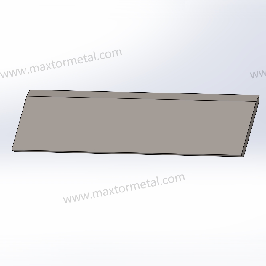
Surface-Integrity bei EDM-Drahterodieren und Schleifbearbeitung
EDM Recast Layer and Microcracks
Wire-EDM and sinker-EDM both produce a recast (white) layer that is metallurgically distinct from the underlying steel matrix. The recast layer:
- Is amorphous or fine-grained resolidified material with elevated carbon content.
- Has Vickers hardness typically 950–1,200 HV — harder and more brittle than the tempered martensite below it.
- Contains tensile residual stresses up to 600–1,000 MPa in severe cases.
- Harbors shallow microcracks (depth 1–20 µm) oriented perpendicular to the machined surface.
These microcracks are structurally equivalent to pre-existing flaws in a fracture-mechanics model. At slot bottoms, where applied and residual stresses are already at maximum, even a 5 µm crack can be sufficient to initiate propagation at service loads. Leaving the recast layer in place at slot roots is a latent reliability defect — regardless of how tightly the fillet radius is held.
The thickness of the recast layer is controlled primarily by EDM energy parameters (peak current, pulse duration, open-circuit voltage) and dielectric flushing conditions. Rough-cut passes typically leave 15–25 µm; fine-cut passes leave 3–8 µm. The goal of a well-designed EDM strategy is to minimize recast thickness on the final pass and then remove what remains by mechanical means.
Skim Cuts and Post-EDM Polishing
The standard process for recast removal at slot bottoms is a two-stage approach:
Stage 1 — EDM skim cuts. After the rough-cut slot form is established, perform one or two additional EDM passes at reduced energy (lower peak current, longer pulse-off time). These skim cuts remove the recast layer from the previous pass, replacing it with a thinner layer typically below 3 µm. The fillet radius is refined in the final skim pass to approach the target R≥0.2 mm.
Stage 2 — Mechanical polishing. Post-EDM polishing at the slot root using fine-grit abrasive stones (600–1,200 grit) or flexible abrasive tools removes the residual skim-cut recast layer and introduces compressive surface stress. Polishing depth of 5–10 µm is typically sufficient. The polished surface should show tempered martensite structure under metallographic examination at 500×, with no visible white layer remaining.
Nital etch (2–4% nitric acid in ethanol) on a representative cross-section is the standard checkpoint: recast appears as an unetched white band, which must be absent at the slot root in production-released blades. For critical slots, the etch check should be performed on a first-article coupon machined from the same lot and EDM program as production blades.
Grinding Burn Detection and Control
Post-EDM grinding — whether to correct fillet form or to finish adjacent surfaces — carries a risk of thermal damage at the slot root. Grinding burn causes:
- Surface softening (over-tempering) in the most common low-heat case.
- Re-hardening (formation of untempered martensite) in severe heat cases.
- Reversal of residual stress to tensile, adding to the existing stress state.
- Micro-cracking in the re-hardened zone.
All of these conditions reduce fracture resistance. The slot bottom is especially vulnerable because coolant access is restricted by slot geometry, and high-alloy tool steel’s lower thermal diffusivity means heat dissipation into the bulk is slower than in carbide or HSS.
Grinding burn controls for slot operations include:
- Reduced depth of cut: ≤0.005 mm per pass for finishing passes near slot roots.
- Flood coolant delivery at the tool-work interface, not general-area flooding.
- Friable abrasive wheel grades (e.g., seeded-gel alumina) that release worn grains before heat buildup.
- Acoustic emission or spindle-power monitoring as real-time thermal load indicators.
Nital etch per ISO 14104 (surface temper etch inspection after grinding) is the industry-standard acceptance method for burn detection, applied on first-article and periodic production coupons. Barkhausen noise analysis provides a quantitative, non-destructive production gate for any lot that required post-EDM grinding near slot roots.
Anlassverfahren zur Steigerung der Zähigkeit
Double Tempering Parameters by Steel Grade
High-carbon, high-chromium cold-work tool steels used in slotted grid blades — including D2 (equivalent to JIS G4404 SKD11, DIN EN ISO 4957 grade 1.2379, ASTM A681 Grade D2), H13, and ledeburitic grades such as M2 — require a structured double-temper protocol to achieve the toughness required at slot bottoms. Single-temper cycles are insufficient for two reasons: they do not fully decompose retained austenite, and they leave secondary martensite (formed from that retained austenite during cool-down) in an untempered, brittle state.
Double tempering protocol by grade:
| Stahlsorte | First Temper | Soak Time | Second Temper | Soak Time | Target HRC |
|---|---|---|---|---|---|
| D2 / 1.2379 / SKD11 | 180–200 °C | 2 h | 180–200 °C | 2 h | 58–62 |
| M2 / 1.3343 | 540–560 °C | 2 h | 540–560 °C | 2 h | 62–65 |
| D3 / 1.2080 | 200–220 °C | 2 h | 200–220 °C | 2 h | 60–63 |
| 8% Cr steels (1.2379 mod.) | 190–210 °C | 2 h | 190–210 °C | 2 h | 59–62 |
The first temper tempers as-quenched martensite and drives partial decomposition of retained austenite into secondary martensite. The second temper then tempers that secondary martensite. Air cooling between tempers to below 50 °C is required to allow the retained-austenite transformation to complete before the second soak begins.
Temperature uniformity within the furnace load is critical: a ±5 °C gradient is the accepted maximum for tool steel tempering. Loads that exceed this produce hardness variation exceeding ±1 HRC within the lot — which translates directly to variation in slot-bottom fracture toughness.
Managing Retained Austenite and Cryo
For D2-type steels austenitized at the upper end of the recommended range (1,030–1,060 °C) to achieve higher dissolution of primary eutectic carbides (M₇C₃) and better wear resistance, retained austenite (RA) content after quench can reach 15–25 vol%. At these RA levels, double tempering alone may not reduce RA to the ≤5 vol% target for high-toughness applications at stress concentrations.
Cryogenic treatment — cooling to −75 °C (dry ice/solvent) or −196 °C (liquid nitrogen), inserted between quench and first temper — drives additional RA transformation before the martensite is tempered. The result is reduced RA (typically to <3 vol% after cryo + double temper), more homogeneous hardness, improved dimensional stability, and measurably better toughness at stress-concentrated features. Cryo is recommended for D2-type slotted blades austenitized above 1,040 °C when XRD measurements indicate >10 vol% RA after quench.
For a detailed framework on how retained austenite control — including XRD-based verification per ASTM E975 and the heat-treatment window for 440C-class blade strip steel — is specified and documented in a supplier qualification program, see Validating 440C Dicer Replacement Blades at HRC 56–58.
At Maxtor Metal, double-temper cycles are executed under SPC control with continuous furnace temperature data logging. Each production lot is charted against ±5 °C control limits for both soak temperature and time-at-temperature. Barkhausen noise screening is applied at the slot-root inspection zone as a post-temper release gate — catching any lot in which a temperature excursion or retained-austenite anomaly has shifted the subsurface stress state out of specification before that lot reaches assembly. This documented process architecture is what separates a blade built to engineering specification from one built to approximate practice.
So prüfen Sie, ob Nutgrundgeometrie und Gefügequalität tatsächlich den Spezifikationen entsprechen
Metallography and Nital Etch Checkpoints
Metallographic cross-sectioning at slot root locations is the ground-truth verification method. First-article and periodic production coupons are prepared as follows:
- Sectioning: Transverse cut through the slot root at mid-length.
- Mounting and polishing: Standard metallographic preparation to 0.05 µm alumina finish.
- Nital etch (2–4%): Reveals martensitic structure, recast white layer, grinding burn zones, and carbide distribution.
- Examination at 200×, 500×, 1,000×: Check for zero recast white layer at the slot root, tempered martensite morphology consistent with the target HRC range, uniform primary carbide distribution with no grain-boundary clustering, and no micro-cracks in the root zone.
Retained austenite quantification by X-ray diffraction (XRD) — per ASTM E975 — is performed on first-article and after any hardening process change. Production release target: ≤5 vol%.
For the incoming material verification side of this traceability chain — reading tool steel MTCs, verifying chemistry acceptance bands by grade, and linking heat numbers to coil tags — see Reading Tool Steel MTC for Strip Blades: A Practical QA Checklist.
Barkhausen and Dye Penetrant Screens
Barkhausen noise analysis (BNA) is a non-destructive magnetic method sensitive to near-surface residual stress and microstructure in ferromagnetic steels. At slot bottoms, BNA detects tensile residual stress elevation (reduced emission amplitude relative to a reference), grinding burn (altered martensite morphology shifts emission spectrum), and subsurface re-hardening zones not visible on the polished surface.
BNA probes are miniaturized to fit slot access geometry. Calibration is performed against a reference set of coupons with known residual stress states confirmed by XRD. Production accept/reject criteria are expressed as Barkhausen amplitude relative to a calibrated baseline: deviations >±15% trigger hold-and-investigate. SAE ARP4462 (Barkhausen Noise Inspection for Detecting Grinding Burns in High Strength Steel Parts) provides a recognized calibration and acceptance framework.
Dye penetrant inspection (DPI) — per ASTM E165 / ISO 3452 — is applied after final polishing and before coating or assembly. DPI is sensitive to surface-open cracks ≥1 µm in width and provides 100% production coverage where sectioning is destructive. Any indication in the slot root zone is cause for rejection.
PPAP-Style Documentation and Metrics
A PPAP-adapted control framework for tooling blades establishes the control plan, measurement system validation (MSA), and production metrics required to sustain slot-root quality:
| Document / Record | Content | Frequenz |
|---|---|---|
| First-article inspection report (FAIR) | CMM radius, hardness traverse, metallography, XRD RA, BNA baseline | Per new tool geometry |
| Control plan | Process parameters and in-process checks for EDM, grinding, tempering | Per blade family |
| SPC charts | Tempering temperature, fillet radius, hardness, BNA amplitude | Per production lot |
| Nital etch record | Photomicrograph archive of slot root cross-section, signed and dated | Per lot (coupon sample) |
| DPI log | Pass/fail per blade serial or lot | 100% production |
| Corrective action log | NCR linkage, root cause, and response action | Per rejection event |
SPC control limits for slot root radius are set at ±0.03 mm around nominal (e.g., 0.20–0.26 mm for an R0.23 mm nominal target). Process capability index Cpk ≥ 1.33 is the production release criterion. Lots falling below Cpk 1.33 on radius or hardness are placed on hold pending engineering review.
Anonymisierte Kundenfallstudie: Bruch eines Würfelschneider-Gittermessers am Nutgrund
The following case comes from a real dicer-blade failure investigation, shared anonymously with the customer’s consent. Identifying details — the processor’s identity, the machine brand, and the exact production line — are withheld at the customer’s request, and the before/after figures have been rounded and normalized to protect commercially sensitive production data. Even so, the mechanism, measurement sequence, and outcome all come from what actually happened on this line, and they show how the principles above play out when slot-root geometry is the dominant cause of grid blade snapping.
Production Scenario
An anonymous poultry processor on a high-throughput food-cutting line experienced repeated failures of its dicer grid/crosscut strip blades. The machine was a commercial rotary dicer of the ~3,000 kg/h class, processing frozen-tempered chicken for further food manufacturing. Typical machines in this class support poultry dicing across roughly 4.8–76 mm, depending on product thickness, feeding method, and machine condition.
This application ran at approximately:
- Product: frozen-tempered chicken
- Dice size: approximately 10–20 mm
- Blade material: 440C Edelstahl
- Target hardness: HRC 56–58
- Blade thickness: approximately 1.5–2.0 mm
- Production: multiple shifts per day
- Failure mode under investigation: grid blade snapping at the bottom of the locating slots
The critical detail is that the blade rarely failed because the cutting edge had worn out. The disruptive failure was a sudden fracture through the strip at a slot bottom — the same failure mode discussed throughout this article.
Original Blade Failure
The original grid blade used a relatively sharp slot-bottom transition, with nominal drawing geometry of approximately R0–0.10 mm. Because the broken blades appeared brittle, the maintenance team initially assumed a material or hardness problem.
During an initial failure review covering the documented fracture events recorded over the investigation period, approximately 70–85% of confirmed fractures were found to initiate in or immediately adjacent to the slot-bottom transition. (The exact sample count is withheld at the customer’s request; the percentage range reflects the bounds of the observed distribution across multiple documentation records.)
The typical sequence was:
- slot-bottom damage → small crack → cyclic crack growth → sudden blade fracture
The cutting edge itself could still appear serviceable immediately before failure. A dicer knife operates under repeated mechanical loading rather than a single static load, so a small geometric discontinuity readily becomes a fatigue initiation site — consistent with the general engineering guidance to use the largest practical fillet radius the functional geometry permits.
First Attempt: Reducing Hardness
Before touching geometry, the processor tried lowering the blade hardness from approximately HRC 58–60 to HRC 55–57, leaving the slot geometry unchanged.
The result reduced catastrophic snapping only slightly, while creating a new problem: edge wear increased, cut quality deteriorated earlier, sharpening/replacement frequency rose, and slot-bottom cracking was still observed. The attempt demonstrated an important principle — reducing hardness can change the failure response without eliminating the stress concentration that initiates the crack. The team therefore returned to the HRC 56–58 target and investigated the geometry.
Measurement Sequence
Step 1 — Map the fracture locations. Every failed grid blade was tagged by machine position, blade orientation, slot number, production hours, product condition, and fracture location. The purpose was to test whether fractures were random. They were not — the same slot-bottom geometry appeared repeatedly in the failure records.
Step 2 — Inspect the slot-bottom radius. Representative blades were checked with an optical comparator or toolmaker’s microscope. Measured radii were approximately R0.05–0.12 mm rather than a consistent larger radius, and some slot bottoms showed localized grinding marks. This matters because a drawing dimension alone does not describe the fatigue condition of a small radius: a nominal R0.10 mm radius with a grinding notch behaves differently from a smooth R0.10 mm radius.
Step 3 — Inspect the fracture origin. Broken blades were examined at low magnification for crack initiation location, grinding marks, local notches, impact evidence, deformation around the slot, and material defects. The recurring finding was that the fracture path tracked the slot-bottom transition rather than occurring randomly through the cutting edge — making a geometry change more logical than further hardness adjustment.
Geometry Modification
The trial retained 440C stainless steel at HRC 56–58. The primary design change was the slot-bottom radius:
- Slot-bottom radius: R0–0.10 mm → controlled R0.20 mm
The objective was not to make the radius “as large as possible” in isolation. The team used the largest radius that could be accommodated without interfering with blade engagement, adjacent components, grid spacing, product clearance, mounting geometry, or required dice dimensions. R0.20 mm should therefore be read as the design target for this application, not a universal dicer specification. The underlying rule is better stated as: use the largest practical slot-bottom radius that the blade geometry and machine clearance allow — consistent with the general principle that increasing a fillet radius reduces local stress concentration wherever geometry permits.
Grinding Process Control
The radius change alone was not considered sufficient. Grinding was standardized to avoid creating a new notch inside the radius. The inspection checklist included:
- Verify slot width
- Verify slot-bottom radius
- Check for visible grinding grooves
- Check for local undercutting
- Inspect the transition between slot wall and bottom
- Verify blade thickness
- Verify hardness on the qualification batch
- Inspect the first production run after installation
This reinforces a point made earlier: a nominal R0.20 mm radius is not automatically fatigue-resistant if the manufacturing process leaves a sharp grinding groove inside the radius.
For the regrind lifecycle framework that governs how many re-sharpenings a blade can sustain before slot-bottom geometry becomes a disqualifying factor, see Nachschleifen von Industrie-Streifenmessern: Schärfschwellen, Verschrottungskriterien und Lebensdauer-Kostenmodell.
Customer Case Results
Rounded, normalized figures from this customer’s production records:
| Metrisch | Originaldesign | R0.20 mm blades |
|---|---|---|
| Material | 440 °C | 440 °C |
| Härte | HRC 56–58 | HRC 56–58 |
| Slot-bottom radius | R0–0.10 mm | R0.20 mm |
| Typical blade life | 70–100 h | 150–190 h |
| Premature snapping | Ausgangslage | ↓ approximately 55–65% |
| Emergency grid changes | Ausgangslage | ↓ approximately 50–60% |
| Unplanned downtime | Ausgangslage | ↓ approximately 45–55% |
| Slot-bottom cracks during the trial period | Recurrent | None observed |
The most important observation was not the increase in average life — it was the change in failure mode. Before the modification, the maintenance team frequently had to respond to an unexpected broken grid blade. Afterward, routine wear and planned replacement became more significant than sudden slot-bottom fracture.
If your failure log shows that emergency grid-blade changes — rather than scheduled replacements — are the primary contributor to line downtime, the OEE model in OEE and Profit Gains from Reducing Coil Change Frequency provides a quantified framework for converting unplanned downtime reduction into a measurable OEE gain.
Example Downtime Calculation
At the customer’s baseline, the line logged approximately 6 emergency grid-blade failures per 1,000 operating hours, each requiring roughly 20–30 minutes of unplanned intervention. Using the 25-minute midpoint:
- 6 × 25 min = 150 min / 1,000 h
With emergency events down by approximately 55% after the change:
- 6 × (1 − 0.55) ≈ 2.7 events → 2.7 × 25 min ≈ 68 min / 1,000 h
The resulting saving was roughly 82 minutes of unplanned downtime per 1,000 operating hours. This is a normalized projection from the customer’s own baseline and post-change records; individual lines will vary with product mix and operating discipline.
Operator Behavior
The investigation also surfaced a human factor. In the early stage, operators sometimes kept running the machine after noticing an unusual sound or a small crack during inspection, risking a small fatigue crack growing into a complete break. The revised procedure introduced a simple rule: any visible crack at the slot bottom = remove and quarantine the blade. Operators were also instructed to inspect slot bottoms, blade seating, abnormal contact marks, product buildup, and evidence of impact. This is another reason the improvement should not be attributed to the R0.20 mm radius alone.
Process Limitations
The result should be interpreted within its operating window. It is most applicable to 440C dicer grid/crosscut strip blades at HRC 56–58, cutting frozen-tempered poultry, with controlled blade installation, normal production loading, and no significant metal contamination or abnormal impact. It should not be read as evidence that R0.20 mm is optimal for every dicer blade. A different blade thickness, slot width, dice size, material, heat treatment, machine, product temperature, or mounting method could require a different radius — cutting capacity and results depend on product condition, feeding method, machine condition, and knife configuration.
Case Conclusion
This anonymized frozen-tempered poultry dicing investigation identified repeated grid-blade fractures at the bottom of locating slots. The original slot geometry used a relatively sharp R0–0.10 mm transition, and replacement blades were made from 440C stainless steel at approximately HRC 56–58. An initial attempt to reduce hardness did not eliminate the problem and increased edge wear.
The subsequent work retained the HRC 56–58 material condition but increased the slot-bottom radius to a controlled R0.20 mm and tightened control of grinding damage and blade inspection. On this customer’s line, typical blade life increased from approximately 70–100 operating hours to 150–190 hours. Emergency grid-blade changes fell by approximately 50–60%, while unplanned downtime associated with blade snapping fell by approximately 45–55%. No slot-bottom cracks were observed during the follow-up period.
The result should not be interpreted as a universal “R0.20 mm doubles blade life” rule. The improvement came from controlling slot geometry together with grinding quality, blade hardness, installation, and operator inspection. The practical design rule is to use the largest slot-bottom radius that the dicer geometry and clearance allow, while avoiding grinding notches or undercuts at the radius transition.
Häufig gestellte Fragen
F: Wie groß muss der minimale Nutgrundradius sein, um den Bruch von Gittermessern zu verhindern?
A: R0,2 mm ist das praktische konstruktive Minimum für die meisten geschlitzten Industriemesser-Geometrien. Unterhalb dieses Werts steigt der Spannungskonzentrationsfaktor Kt steil an —auf Werte von 7 bis 12— und führt in Kombination mit den typischen Prozessschwankungen bei Eigenspannungen und Oberflächengüte zuverlässig zu Bedingungen für einen Sprödbruch am Nutgrund. Größere Radien (R0,3–0,5 mm) bieten zusätzliche Sicherheitsreserven und sollten überall dort geprüft werden, wo es die Funktion der Nut zulässt.
F: Warum brechen geschlitzte Messer am Nutgrund und nicht an der Schneidkante?
A: Der Nutgrund konzentriert elastische Spannungen, die unter Biege- und zyklischer Belastung um ein Vielfaches höher sind als die angelegte Nennspannung. Die Schneidkante ist zwar Kontaktspannungen ausgesetzt, profitiert während des Betriebs jedoch von einer druckbeanspruchten Kontaktgeometrie. Der Nutgrund wirkt als geometrischer Kerbwirkungsträger, der zudem Eigenspannungen (Zugspannungen) aus Drahterosion (EDM) und Härtung akkumuliert — was ihn zum wahrscheinlichsten Ort für den Beginn eines Bruchs macht.
F: Wie verursacht die EDM-Neuaufschmelzschicht Risse in Werkzeugstahlmessern?
A: Die EDM-Neuaufschmelzschicht (Weiße Schicht) ist eine erstarrte, amorphe Schicht, die härter als der Grundmartensit ist —typischerweise 950–1.200 HV— und durch die rasche Erstarrung Zug-Eigenspannungen sowie flache Mikrorisse aufweist. Diese Mikrorisse stellen im Sinne der Bruchmechanik vorbestehende Schwachstellen dar. Unter zyklischer Belastung an einem kerbwirkungsbehafteten Nutgrund breiten sie sich in das Substrat aus und können innerhalb der ersten Betriebsstunden zu einem schnellen Bruch führen, wenn die Schicht vor dem Einsatz des Messers nicht entfernt wird.
F: Was ist Doppel-Anlassen und warum ist es für geschlitzte Werkzeugstahlmesser erforderlich?
A: Doppel-Anlassen (zweimaliges Anlassen) umfasst zwei vollständige Anlasszyklen (Haltezeit + Luftabkühlung auf Raumtemperatur + erneute Haltezeit). Der erste Zyklus lässt den Härtemartensit an und wandelt Restaustenit teilweise in Sekundärmartensit um. Der zweite Zyklus lässt diesen Sekundärmartensit an. Ein einfaches Anlassen lässt den Sekundärmartensit unanganlassen und spröde — ein kritischer Mangel an kerbwirkungsbehafteten Stellen wie dem Nutgrund. Das Doppel-Anlassen ist Standardpraxis gemäß den Spezifikationen ASTM A681 D2 und JIS G4404 SKD11 für zähigkeitskritische geschlitzte Werkzeuge.
F: Wie erkennt man Schleifbrand in einer Nut, die für Standardprüfköpfe zu schmal ist?
A: Die Barkhausen-Rauschanalyse (BNA) mit miniaturisierten, für den Nutzugang angepassten Sonde ist die empfindlichste verfügbare zerstörungsfreie Prüfmethode. BNA erkennt oberflächennahe Veränderungen der magnetischen Domänenstruktur, die durch thermische Schädigung, Neuhärtung oder Zug-Eigenspannungen verursacht werden — alles charakteristische Merkmale von Schleifbrand. Eine Nital-Ätzung nach ISO 14104 an metallografischen Schliffen bietet eine zerstörende Bestätigung an Erstmusterprüfungen und periodischen Produktionsproben.
F: Welcher Restaustenitgehalt ist nach dem Härten von geschlitzten Messern aus D2-Stahl zulässig?
A: Das Freigabeziel für die Produktion nach dem Härten und Doppel-Anlassen liegt bei ≤5 Vol.-% Restaustenit, gemessen durch Röntgendiffraktometrie (XRD) nach ASTM E975. D2-Stähle, die über 1.040 °C austenitisiert werden, können nach dem Abschrecken 15–25 Vol.-% Restaustenit aufweisen. Wenn der Restaustenitgehalt 10 Vol.-% übersteigt, wird eine Tiefkühlbehandlung (Kryobehandlung) bei −75 bis −196 °C zwischen dem Abschrecken und dem ersten Anlassen empfohlen, um die Gefügeumwandlung vor dem Anlassen weiter voranzutreiben.
Welche zerstörungsfreien Prüfverfahren (ZfP) sollten geschlitzte Gittermesser vor dem Versand durchlaufen?
Ein vollständiger Produktionsprüfablauf sollte Folgendes umfassen: Barkhausen-Rauschanalyse (BNA) im Nutgrundbereich zur Erkennung von Schleifbrand und Eigenspannungsanomalien; Eindringprüfung (DPI) nach ASTM E165 / ISO 3452 auf oberflächenoffene Risse; sowie Radiusverifizierung durch optische Profilometrie oder KMM (CMM). Die Rockwell-C-Härteprüfung dient der Prozesskontrolle und ersetzt nicht die genannten Methoden. Die Eindringprüfung bietet eine 100%ige Abdeckung der Messerklinge; BNA und Radiusprüfungen sind die primären Qualitätsmerkmale für die strukturelle Integrität des Nutgrundes.
Maxtor Metal stellt Kunden das vollständige ZfP-Dokumentationspaket zur Verfügung — einschließlich BNA-Amplitudenaufzeichnungen nach Nutzonen, DPI-Prüfprotokollen nach Messerseriennummer und KMM- bzw. Profilometrie-Radiusberichten — formatiert für Lieferanten-Audits und Prüfungen nach PPAP-Standard.
F: Wie werden SPC-Kontrollgrenzen für den Hohlkehlenradius von Nuten in der Messerfertigung festgelegt?
A: Setzen Sie den Nominalradius auf den Mittelpunkt des funktionellen Toleranzbereichs. Definieren Sie Überwachungskontrollgrenzen bei ±0,03 mm um den Nennwert. Berechnen Sie den Cpk-Wert aus den Daten der Erstmusterprüfung und fordern Sie Cpk ≥ 1,33 als Kriterium für die Freigabe der Serienproduktion. Validieren Sie das Messsystem (optische Profilometrie oder KMM) vor dem Start von SPC mit einer Messsystemanalyse (Gage R&R), um sicherzustellen, dass Messabweichungen die Schätzungen der Prozessabweichung nicht verfälschen.
Fazit
Das Brechen von Gittermessern am Nutgrund ist kein zufälliges Versagensmuster. Es ist das deterministische Ergebnis des Zusammentreffens von Spannungsspitzen, Oberflächenfehlern und unzureichender Zähigkeit an derselben Stelle des Werkzeugs.
Größere Übergangsradien (R≥0,2 mm) reduzieren den Kerbwirkungszahl-Faktor Kt um etwa 50 % im Vergleich zu scharfkantigen Geometrien. Dies senkt die Spannungsspitze am Nutgrund direkt und verlängert die durch Bruchgefahr begrenzte Standzeit. Das Doppel-Anlassen — mit speziell auf die jeweilige Stahlsorte und den Restaustenitgehalt abgestimmten Parametern — wandelt das spröde Härtegefüge nach dem Abschrecken in eine zähe Matrix um, die in der Lage ist, die Verformungsenergie zu absorbieren, die andernfalls die Rissausbreitung durch den Messerkörper vorantreiben würde.
Geometrie und Metallurgie allein reichen nicht aus, wenn die Prozessintegrität nicht gewahrt bleibt. Durch EDM entstandene Wiederaufschmelzschichten (Recast Layer) müssen im Feinschnitt- (Skim-Cut) und Polierablauf mechanisch entfernt werden. Schleifoperationen im Bereich des Nutgrundes müssen kontrolliert werden, um Schleifbrand zu vermeiden, und mittels Barkhausen-Rauschanalyse überprüft werden. Eigenspannungen müssen durch eine präzise Steuerung der Abschreckgeschwindigkeit und ein Spannungsarmglühen/Anlassen gesteuert werden — und dürfen nicht einfach aufgrund der erreichten Härte als erledigt angesehen werden.
Das finale Element ist die systematische Verifizierung: Nital-geätzte Querschliffe, BNA-Screening (Barkhausen-Rauschanalyse), Eindringprüfung (Farbeindringverfahren) und SPC-überwachte Prozessaufzeichnungen schaffen eine dokumentierte Qualitätskette von der Nutradius-Spezifikation bis zur Auslieferung. Die Standardisierung dieser Spezifikationen und Prüfungen über das gesamte Messerfertigungsprogramm hinweg wandelt die Zuverlässigkeit der Klingen von einem Zufallsergebnis im Betrieb zu einer gezielt entwickelten und vor dem ersten Einsatz verifizierten Eigenschaft.
Maxtor Metal provides customers specifying precision slotted grid blades with batch-level documentation covering slot-root radius measurement records (CMM or optical profilometry), EDM skim-cut and nital etch verification, double-temper batch records with continuous furnace data logs, XRD-based retained austenite results, and Barkhausen noise screening reports at slot-root zones. Customers running formal supplier qualification programs can request the full documentation package before first shipment to validate that slot-root geometry and heat-treat parameters are controlled to engineering specification, not estimated from process experience.
Über den Autor
Jesse Xu — Senior Quality Engineer, QA (Quality Assurance), Maxtor Metal
Jesse Xu is a Senior Quality Engineer with 15 years of experience in industrial blade manufacturing and quality assurance. His work focuses on failure analysis: determining whether blade failures such as edge chipping and premature wear originate from heat-treatment process deviations or from material segregation (carbide/banding) issues. He holds the ASQ Certified Quality Engineer (CQE) credential, is an ISO 9001 Lead Auditor, and is certified to ASNT NDT Level II.
Offenlegung & Kontakt
This article is published by Maxtor Metal, a manufacturer and supplier of custom, precision-ground industrial blades. It is provided for technical education and product explanation; because it references Maxtor Metal products, readers should be aware of a potential commercial interest. Technical claims are referenced to publicly available standards (ISO, ASTM, SAE) and established engineering literature, and readers are encouraged to verify specifications against their own application requirements.
For questions about this article, blade design specifications, or technical support, please reach out via our Kontaktseite.

 English
  Spanish
  Italian
  French
  Portuguese
  Russian
  German
  Arabic
  Hindi
Hindi  Vietnamese
  Indonesian
  Japanese
  Korean