

주요 요점:
- 기본 메커니즘슬리팅 분진(Slitting Dust) 발생은 단순히 무뎌진 절삭날 때문만은 아닙니다. 이는 주로 나이프 측면(Flank)의 미세 돌기(Micro-asperities)가 새로 파단된 원단 단면(Web edge)을 긁고 지나가면서 발생하는 마찰력에 의해 유발됩니다.
- 측정 임계값나이프 측면(Flank) 표면 조도를 일반 상용 수준(Ra 0.4~0.8 µm)에서 초경면 연마(Ra < 0.1 µm)로 개선하면 미세 마찰력이 최대 60% 감소하여 고속 생산 라인에서의 입자 탈락(Particulate shedding) 현상을 완벽히 차단할 수 있습니다.
- 금속학적 선정범용 D2 또는 SKD11 강재는 초경면 연마(Superfinishing) 과정에서 카바이드 탈락(Carbide pull-out) 현상이 발생하기 쉽습니다. 지속적인 원단 장력 상태에서 Ra < 0.1 µm 조도를 달성하고 유지하려면 분말 야금 공구강(PM-M4) 또는 서브 마이크론 텅스텐 카바이드(초경) 재질이 필수적입니다.
- 시스템적 정밀도경면 가공(Mirror-finish) 나이프는 2차 마찰(Secondary rubbing)을 방지하기 위해 축 방향 요동(Axial runout) ≤ 0.002 mm, 정확한 경사각(Cant angle), 보정된 전단 오버랩 깊이(Shear overlap depth)를 포함한 엄격한 기계 세팅 공차와 결합되어야 합니다.
이 네 가지 원칙은 Maxtor Metal의 연적용 기술 팀이 연포장, 부직포 및 특수지 라인의 '제로 분진 가공 프로그램'용 원형 슬리팅 나이프를 검증할 때 적용하는 핵심 엔지니어링 프레임워크입니다.
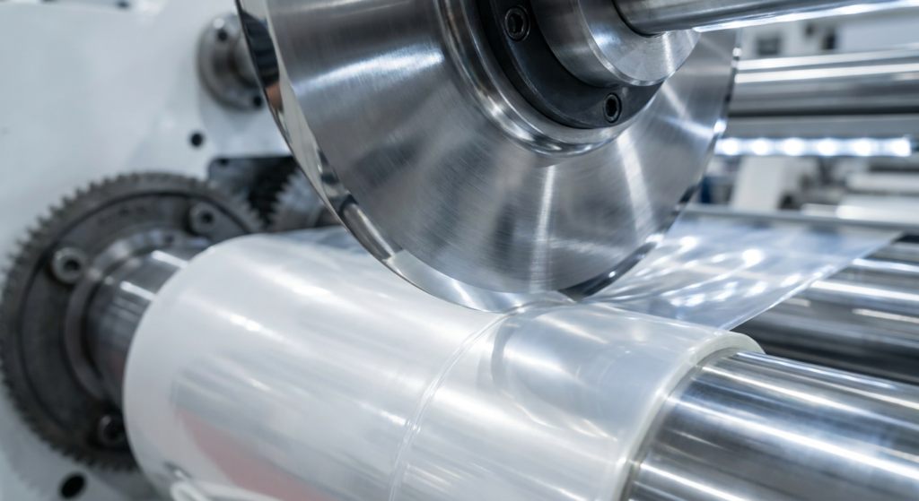
연포장, 산업용 섬유, 부직포 및 특수지 고속 가공(Converting) 공정에서 미세 입자 오염은 계획되지 않은 라인 정지의 주요 원인입니다. 현장 작업자가 흔히 "원단 장력 불량"이나 "원자재 원단(Roll) 결함"으로 진단하는 문제는 대부분 한 가지 근본 원인, 즉 전단 절단점(Shear cut point)에서 즉각 발생하는 슬리팅 분진(Slitting dust)으로 귀결됩니다.
미세한 폴리머 조각, 섬유 파편 또는 무기 코팅 입자가 슬리팅된 원단 롤에 누적되면 후공정에서 심각한 불량이 발생합니다. 광학 검사 시스템이 허위 결함 알람을 울리고, 인쇄 공정에서는 분진 공극으로 인해 핀홀(Pinholes)이 발생하며, 정전기가帯電된 원단 롤이 공기를 감싸면서 권취 중 망원경 현상(Telescoping, 권취 쏠림)을 유발합니다.
기존의 정비 관행은 나이프의 날카로움(절삭날 반경, Edge radius)에만 집중하는 경향이 있지만, 마찰학(Tribology) 연구와 현장 계측 결과에 따르면 날 반경은 문제의 절반에 불과합니다. 미세 분진 발생을 유발하는 핵심 원인은 바로 나이프 측면(Flank)의 표면 조도 프로파일(Surface roughness profile)입니다.
본 기술 보고서는 로터리 전단 슬리팅(Rotary shear slitting)의 절삭 영역 역학을 분석하고, 표면 조도 지표(Ra, Rz, Rmax)의 영향을 정량화하며, 공구강의 미세조직(Microstructure)을 평가하고, 제로 분진(Zero-dust) 슬리팅 성능을 달성하기 위한 운전 변수를 제시합니다.
슬리팅 분진(Slitting Dust) 발생의 미시적 역학: 측면 조도가 원단(Web) 침식을 유발하는 원리
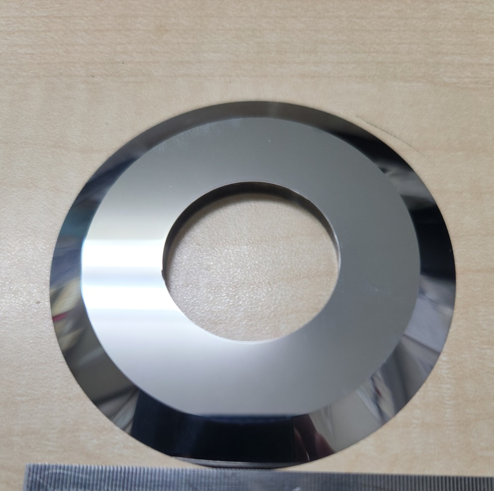
미립자 오염을 제거하기 위해, 가공 공정 엔지니어는 2단계 시어 슬리팅 시퀀스를 분석해야 합니다. 시어 슬리팅은 단순한 면도날 절단 동작이 아니라, 상부 접시형 원형 칼날(dished circular knife)과 하부 암 슬리터 밴드(female slitter band) 사이에서 발생하는 제어된 기계적 파단입니다.
1단계: 탄소성 압축 → 소재가 상하부 칼날 가장자리 사이에서 압착됩니다.
2단계: 미세 균열 개시 → 전단 응력이 극한 항복 강도를 초과하여 균열이 전파됩니다.
3단계: 플랭크 접촉 및 웹 이동 → 파단된 웹 가장자리가 상부 칼날 플랭크를 따라 하류로 미끄러집니다.
미세 요철 드래그 vs. 깨끗한 전단 파단
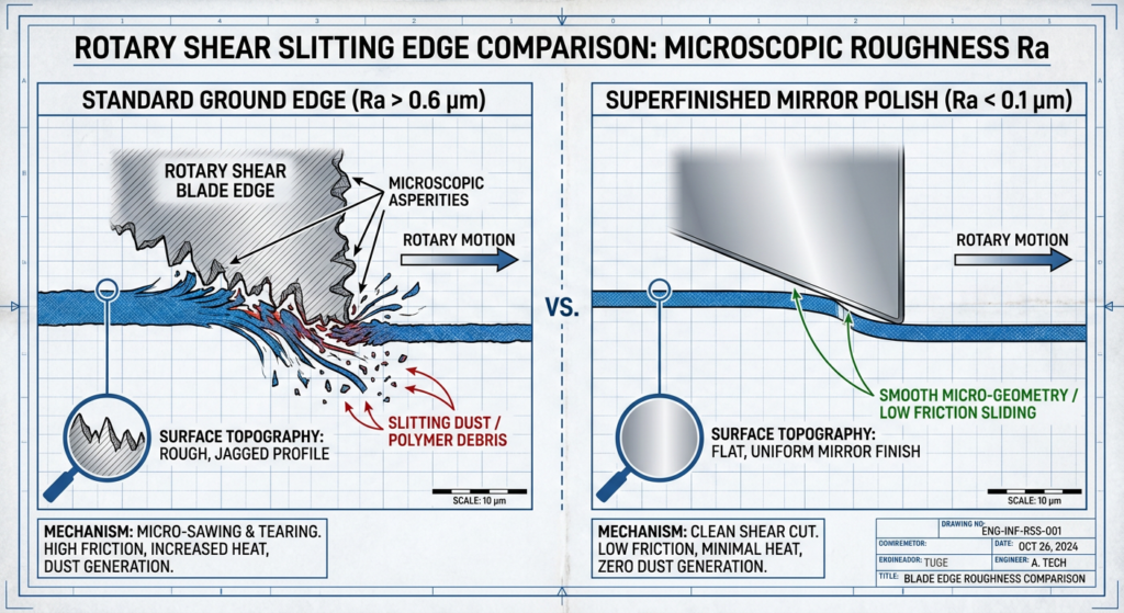
3단계 동안, 새로 형성된 웹 가장자리는 상부 원형 칼날의 측면 플랭크를 따라 이동합니다. 표준 생산용 연삭 휠을 사용하여 칼날을 연삭할 때, 연삭 휠은 미세 요철(micro-asperity)이라고 불리는 방향성 리지(ridge)를 남깁니다.
200x 광학 배율에서 표준 연삭된 칼날 플랭크는 미세한 톱과 유사합니다. 웹 가장자리가 분당 300미터를 초과하는 속도로 이러한 피크를 통과할 때, 요철이 개별 폴리머 사슬이나 셀룰로오스 섬유를 잡아챕니다. 깨끗하게 분리되는 대신, 소재는 국부적인 미세 찢어짐, 마모 및 전단 변형을 겪게 됩니다. 찢어진 소재는 미세한 공기 중 미립자나 정전기로 부착된 이물질로 떨어져 나갑니다. 이는 선도적인 슬리팅 칼날 공급업체의 엔지니어링 문서와 일치하며, 거친 칼날 표면은 웹이 플랭크를 통과할 때 슬릿 가장자리를 마모시키고, 측정된 표면 조도가 유사해 보이더라도 재연삭 품질에 따라 분진이 증가할 수 있다고 지적합니다.[2]
3체 연삭 마모 피드백 루프
초기 분진 입자가 탈락하면 가속화되는 열화 사이클이 시작됩니다:
- 입자 포집: 미세한 이물질이 상부 칼날 베벨과 하부 암 나이프 링 사이의 미세 간극에 끼입니다. 상부 칼날 팁의 베벨 기하학적 형상은 이 3체 연삭 루프에 노출되는 접촉 면적의 크기도 결정합니다. 복합 미세 베벨은 입자로 인한 치핑으로부터 팁을 보강하는 동시에 노출되는 플랭크 표면을 줄여줍니다. 강성 중심의 베벨 선정 프레임워크는 다음을 참조하십시오. 원형 슬리터 칼날을 위한 싱글, 더블 및 컴파운드 베벨.
- 3체 마모: 포집된 경질 입자(예: 플라스틱 필름의 탄산칼슘 필러 또는 부직포의 이산화티타늄 안료)는 연삭 래핑 컴파운드처럼 작용합니다.
- 플랭크 스커핑 및 무뎌짐: 이물질이 칼날 플랭크를 긁어 표면 조도를 증가시키는 동시에 주 절삭날을 둥글게 만듭니다.
- 분진의 기하급수적 급증: 칼날 표면이 거칠어지고 무뎌짐에 따라 소재의 찢어짐 깊이가 깊어져 더 많은 양의 분진이 발생합니다.
소재 기재 민감도
다양한 가공 기재는 거친 칼날 플랭크에 노출될 때 서로 다른 파손 모드를 나타냅니다:
- BOPP, PET 및 PE 필름: 높은 마찰은 절단 경계에서 국부적인 열 에너지를 생성합니다. 마찰로 인한 가열은 미세 용융에 이어 취성 열 파단을 유발하여 미세한 흰색 폴리머 분말을 생성합니다.
- 부직포 및 합성 섬유: 미세 요철이 개별 필라멘트를 잡아채어, 전단하기보다는 결합된 매트릭스에서 뽑아냅니다(섬유 마모).
- 코팅지 및 판지: 거친 플랭크가 무기물 탑 코트(클레이/라텍스)에 균열을 일으켜 공구강 가장자리를 빠르게 마모시키는 광물 분진을 방출합니다.
표면 계측학(Metrology) 분석: Ra < 0.1 µm가 제로 분진(Zero-Dust) 슬리팅의 임계값인 이유
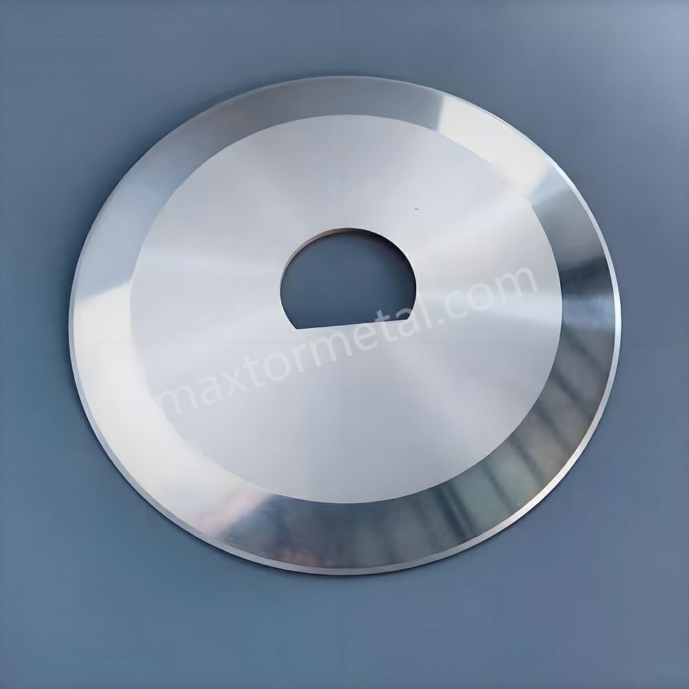
표면 조도를 정량화하려면 “연마됨” 또는 “광택 마감”과 같은 주관적인 용어를 넘어서야 합니다. 공장 관리자는 Ra, Rz 및 Rmax 프로파일 매개변수를 정의하는 ISO 4287 시리즈와 측정값을 허용 오차 한계와 비교하는 방법을 규정하는 ISO 4288에 따른 조도계 테스트를 사용하여 표면 측정 매개변수를 지정해야 합니다.[1]
- Ra (중심선 평균 거칠기): 평균선으로부터의 프로파일 높이 편차의 산술 평균입니다.
- Rz (평균 최대 높이): 5개의 연속 기준 길이에서 측정된 최대 프로파일 높이의 평균입니다.
- Rmax: 전체 평가 길이에 걸친 개별 최대 프로파일 높이(최대 피크-투-밸리 거리)입니다.
로터리 슬리팅에서, Ra는 정상 상태 마찰을 직접 제어합니다., 하는 동안 Rz는 피크 요철이 기재 섬유를 잡아챌지 여부를 결정합니다..
| 표면 조도 등급 | 표면 거칠기 (Ra) | 최대 높이 (Rz) | 표면 토포그래피 프로파일 | 슬리팅 분진 발생 수준 | 일반적인 가공 적합성 및 한계 |
|---|---|---|---|---|---|
| 일반 연삭 | Ra 0.4 – 0.8 µm (16–32 RMS) | Rz 1.6 – 3.2 µm | 뚜렷한 원주 방향 연삭 흔적, 거친 미세 피크. | 심각함: 지속적인 폴리머 박리 및 섬유 마모. | 두꺼운 고무 트리밍 또는 저속 골판지 가공. 필름에는 부적합. |
| 정밀 연삭 | Ra 0.2 – 0.4 µm (8–16 RMS) | Rz 0.8 – 1.6 µm | 미세 연삭 결, 완만한 피크 높이 감소. | 보통: 150 m/min 이하의 판지 가공에 적합, 박막 필름 가공 시 정전기 분진 발생. | 표준 종이 가공 및 기본 포장 라인. |
| 초정밀 경면 연마 | Ra < 0.1 µm (2–4 RMS) | Rz < 0.4 µm | 마찰이 거의 없는 경면 표면 형상, 방향성 연삭 결 없음. | 제로에 가까움: 깔끔한 전단 파단 및 소재 끌림 현상 없는 부드러운 슬라이딩 접촉. | 고속 BOPP/PET 필름, 배터리 분리막, 부직포 및 의료용 포일. |
정밀 연삭 표면(Ra 0.3 µm)에서 초정밀 경면 연마 표면(Ra < 0.1 µm)으로 업그레이드할 경우, 정밀 연삭된 공구강에 대한 제어된 마찰계 시험에서 칼날 플랭크(flank)와 웹(web) 사이의 운동 마찰 계수가 약 50%에서 60%까지 감소할 수 있습니다. 이는 모의 슬리팅 접촉 조건에서 Ra 0.3 µm와 Ra < 0.1 µm PM-M4 샘플 간의 Maxtor Metal 자체 비교 테스트 결과와 일치하는 범위입니다. 이러한 마찰 감소는 정상 상태의 플랭크 접촉을 절단면에서 소재가 뜯겨 나가는 데 필요한 임계 전단 응력 이하로 유지하여, 다음을 줄이는 데 기여합니다. 슬리팅 분진 발생 원천적으로 방지합니다.
이 임계값을 올바르게 정의하는 것이 중요합니다. 가공 산업 엔지니어링 가이드에 기록된 바와 같이, 분진 발생은 표면 조도만으로 결정되지 않습니다. 엔지니어링 자료에 따르면 칼날의 예리함, 전단(cant) 각도, 측면 하중(side load), 웹 소재, 나이프 회전 속도, 오버랩, 런아웃, 웹 장력 등 여러 상호 작용 변수가 결합되어 라인에서 발생하는 분진의 양을 결정합니다. 초정밀 연마 블레이드는 플랭크 마찰로 인한 분진 발생 요소를 줄여주지만, 생산 공정에서 분진 발생을 제로에 가깝게 구현하려면 올바른 셋업 기하학적 구조(setup geometry)가 반드시 병행되어야 합니다.
고성능 가공 라인을 평가하는 엔지니어들은 다음을 검토할 수 있습니다. 정밀 연삭 전단 칼날 및 로터리 슬리팅 나이프 초정밀 연마 표면 측정 기술이 미세 요철(micro-asperity)로 인한 끌림 현상 제거에 어떻게 기여하는지 확인할 수 있습니다.
현장 적용 사례 연구: 고생산성 특수지 가공(Converting)
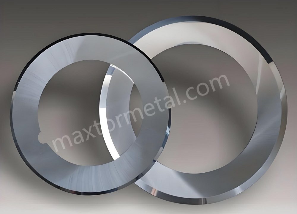
이러한 원리가 실제 작동 성능으로 어떻게 이어지는지 설명하기 위해, 원형 쉐어 슬리팅 나이프를 사용하는 대용량 연속 특수지 가공 공장의 사례를 살펴보겠습니다. 이 라인은 기존 합금 공구강 원형 나이프를 사용하여 24시간 교대 근무 체제로 하루 약 100톤의 롤 용지를 가공합니다.
| 매개변수 | 업그레이드 전 (기존 합금 공구강) | 업그레이드 후 (나이프 및 공정 개선 결합) |
|---|---|---|
| 평균 칼날 마모 수명 | 기준선 | +250% |
| 슬리팅 분진 및 미세 부스러기 | 심각한 공기 중 분진 발생, 거친 절단면, 빠른 마모 | −85% |
| 가공 라인 가동 시간(Uptime) | 약 48시간마다 1회 정비 정지 | +40% |
이 사례에서 관찰된 손상 메커니즘은 앞서 언급한 근본 원인 분석과 직접적인 관련이 있습니다. 탄산칼슘, 이산화티타늄, 카올린 클레이 필러가 함유된 특수지의 경우, 생산이 진행됨에 따라 기존 칼날의 날끝이 점진적으로 마모되었습니다. 예리함이 저하되면서 절단 방식이 정밀한 전단(shearing)에서 웹에 대한 미끄러짐, 압착 및 찢어짐으로 변하여 훨씬 더 많은 종이 분진이 발생했습니다. 높은 플랭크 표면 거칠기 역시 이 라인의 3대 주요 툴링 문제 중 하나로 확인되었습니다.
데이터 출처: 공개된 공급업체 현장 적용 사례로, 고객의 신원 및 상세 생산 기록은 공개되지 않았습니다. 따라서 보고된 성능은 독립적으로 검증된 테스트 데이터가 아닌 공급업체 보고 현장 데이터로 취급되어야 합니다. 보고된 −85%의 분진 및 부스러기 감소는 나이프와 공정 업그레이드를 병행한 후에 달성되었습니다. 표면 조도는 독립적으로 분리된 원인이 아니라 관리된 변수 중 하나였습니다. Ra < 0.1 µm는 현장 결과에 대한 단독 원인이 아닌 엔지니어링 관리 목표로 이해되어야 합니다.
이 사례는 초정밀 경면 연마 블레이드(Ra < 0.1 µm)가 분진 제로 전략의 필수 요소 중 하나이지만, 예리함, 기하학적 구조 및 장비 상태라는 더 넓은 시스템 내에서 작동한다는 점을 뒷받침합니다. 다음 섹션의 측정 및 야금학적 결정은 이러한 블레이드가 갖추어야 할 요건과 장기적으로 성능을 유지하는 방법을 정의합니다.
Maxtor Metal의 애플리케이션 엔지니어링 팀은 특수지 및 필름 가공 프로젝트 전반에서 이와 일치하는 결과를 관찰했습니다. 다른 모든 설정 조건이 동일한 상태에서 기존의 정밀 연삭 D2 나이프를 초정밀 연마 블레이드(Ra < 0.1 µm, PM-M4 모재)로 교체했을 때, 분진 관련 품질 문제로 인한 칼날 교체 주기가 일반적으로 2~3배 연장되었습니다. 본 보고서에 기술된 Ra 임계값 및 야금학적 선택 기준은 해당 프로젝트에 적용된 것과 동일한 엔지니어링 제어 기준을 반영합니다.
야금학 및 미세조직: Ra < 0.1 µm 조도를 유지하는 강재 선정
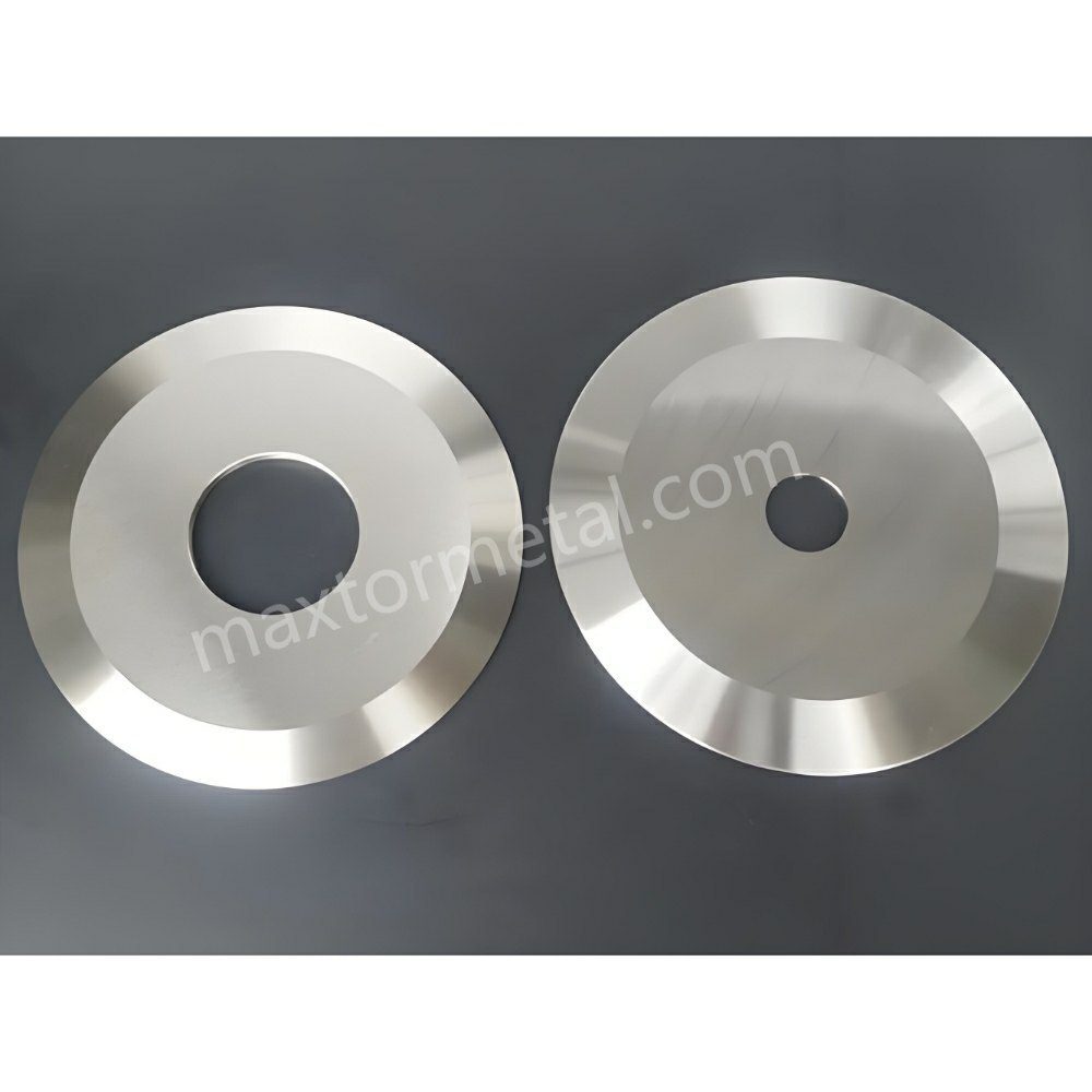
칼날 제조업체는 연삭 작업장에서 저품질 공구강을 경면으로 연마할 수 있지만, 소재의 내부 미세조직이 불안정하면 생산 부하가 걸릴 때 해당 표면 조도가 빠르게 저하됩니다.
기존 D2 / SKD11의 탄화물 탈락(Carbide Pull-Out) 문제점
AISI D2 (1.2379 / SKD11)와 같은 기존의 냉간 공구강은 높은 크롬 및 탄소 함량 덕분에 산업용 칼날에 널리 사용됩니다. 그러나 잉곳 주조 D2는 크기가 15 µm에서 30 µm에 이르는 거대한 1차 공정 크롬 탄화물(M₇C_3)을 포함하고 있습니다.
연삭 기술자가 D2를 Ra < 0.1 µm 수준으로 슈퍼피니싱하려고 할 때, 다이아몬드 래핑 휠이 이 크고 취성이 강한 탄화물을 건드려 상대적으로 연한 마르텐사이트 기질(matrix)에서 이탈시킵니다. 이러한 현상은 탄화물 탈락(carbide pull-out), 으로 불리며, 칼날 플랭크 표면에 미세한 구멍(pit)을 남깁니다. 이러한 미세 구멍은 이물질을 수집하고 날카로운 캐비티 가장자리를 형성하여 고속 슬리팅 작업 중 마모를 유발하는 지점이 됩니다.
분말 야금(PM) 및 미세 입자 카바이드 솔루션
탄화물 탈락 없이 Ra < 0.1 µm의 표면을 유지하기 위해, 컨버팅 공정에서는 고급 야금 합금으로 전환해야 합니다.[3] PM-M4와 같은 분말 야금 등급은 기존 D2에서 발견되는 거친 크롬 탄화물 클러스터보다 초미세 가공에 훨씬 더 적합한 미세하고 균일하게 분포된 바나듐 탄화물 구조를 제공합니다.
- 분말 야금강 (PM-M4, PM-A11 / CPM 10V): 가스 분무화(gas atomization) 및 열간 등가압 성형(HIP)을 통해 생산되는 PM강은 기질 전체에 고르게 분포된 초미세 구형 바나듐 탄화물(VC)을 특징으로 합니다. 탄화물 크기가 2 µm 미만으로 유지되므로 미세 구멍(micro-pitting) 발생 없이 Ra < 0.05 µm까지 연속 래핑이 가능합니다.
- 미세 입자 텅스텐 카바이드: 고마모성 애플리케이션(리튬 이온 배터리 분리막 필름, 유리 섬유 함유 부직포)의 경우, 10–12% 코발트 바인더가 포함된 미세 입자 텅스텐 카바이드(입자 크기 0.5–0.8 µm)는 극도의 경도(HRC 75–80)를 제공하는 동시에 수개월간의 연속 가동 중에도 결함 없는 경면 마무리를 유지합니다.
고내구성 공구를 필요로 하는 가공 공장에서는 다음을 검토할 수 있습니다: 산업용 원형 슬리터 칼날 (분말 야금 및 미세 입자 텅스텐 카바이드 합금으로 제작).
| 슈퍼피니싱 유지력을 위한 강종 비교 | Detail |
|---|---|
| 기존 D2 / SKD11 | Coarse Carbides 20µm → Carbide Pull-Out → Micro-Pitting (Ra Degrades) |
| PM-M4 / CPM 10V Steel | Fine Carbides < 2µm → Smooth Lapping → Retains Ra < 0.1 µm Finish |
| Tungsten Carbide (Fine) | Sub-Micron Grains → Mirror Polish → Maximum Wear & Zero Dust |
Deep Cryogenic Treatment (-185°C)
After vacuum heat treatment and triple tempering, premium circular knives undergo deep cryogenic treatment at -185°C (-300°F) for 24 hours. Cryogenic processing converts residual retained austenite into stable martensite while precipitating microscopic eta-carbides. This stabilizes the steel matrix, preventing dimensional distortion and preventing stress-induced surface roughening during high-speed rotation. The sequence in which cryogenic treatment, heat treatment, and final lapping are ordered matters as much as the treatment parameters themselves — this process discipline is covered in the next section.
A First-Party Engineering Perspective: Why Finish Retention Outlasts Finish Achievability
A common misconception among converters is that an Ra < 0.1 µm mirror polish is simply a grinding-shop deliverable. In practice, the harder problem is retention under service — keeping that finish through heat treatment, handling, mounting, and high-speed contact. This is where process sequence matters more than the final grinding pass.
From Maxtor Metal’s own shop-floor experience across paper, plastics, and metal-slitting lines, three sequence decisions consistently separate blades that hold a mirror finish from blades that merely start with one:
- Cryogenics Before Lapping: When deep cryogenic stabilization precedes ultra-fine diamond lapping, the austenite-to-martensite conversion is complete before final grinding. Lapping then acts on a dimensionally stable matrix, so the polished surface does not “rewarp” or shed as-transformed carbides in service. Sequence these steps in the reverse order and the finish is vulnerable to surface roughening within weeks of operation.
- Finish Ground on the Mounting Reference, Not as a Standalone Blank: Superfinished flanks are most stable when lapped after the bore and lateral faces are final-ground to their ±0.001 mm tolerances (see the runout section). Lapping a blank first, then grinding the bore, risks re-introducing micro-distortion at the very flank that defines dust performance.
- Documented Material Traceability: Requiring EN 10204 Type 3.1 mill certificates and batch-level traceability means the carbide distribution — and therefore the finish-retention capability — is verifiable on paper, not just on the surface. This turns an otherwise invisible metallurgical claim into an auditable control variable.
These sequencing principles are not found in generic tool-grade datasheets; they reflect first-party process knowledge accumulated through dedicated zero-dust converting programs. For teams planning a Ra < 0.1 µm upgrade, treating the process order with the same rigor as the final Ra number is the single most practical lever for lasting, measurable dust reduction.
설비 세팅 매트릭스: 슬리팅 잔여물(Debris)을 제어하는 2차 변수 관리
While specifying superfinished blades with Ra < 0.1 µm removes the primary cause of dust, incorrect machine setup can force even the best knife to rub against the web, reintroducing debris.
Shear Overlap Depth and Cant Angle Calibration
The interaction between the top circular knife and bottom female slitter must mimic a precise pair of scissors:
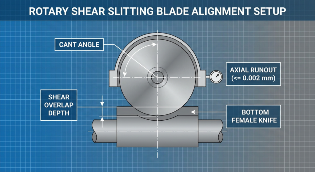
- Cant Angle (Side Angle): The angle at which the top dished blade leans into the bottom knife band. Too high a cant angle (> 1.0°) causes excessive point-loading, accelerating flank wear and creating steel dust. Too low an angle (< 0.2°) leads to blade separation and web tearing. For superfinished blades, maintain a cant angle between 0.35° and 0.50°. Maxtor Metal’s field engineering team uses this window as the commissioning baseline when setting up superfinished circular knives on film and nonwoven slitting lines; angles outside this range are the most common setup cause of premature mirror-finish degradation in the first 48 hours of production.
- Shear Overlap Depth: Top blade penetration into the bottom ring should be kept to the minimum required for a clean cut (typically 0.5 mm to 0.8 mm for films under 200 microns). Excessive overlap increases the contact arc distance between the weband the blade flank, increasing rubbing and dust generation. For a detailedtreatment of how overlap, cant angle, and preload interact during shearslitting setup, see 제로 클리어런스 전단 슬리팅을 위한 스프링 로디드 셋업: 오버랩, 캔트각 및 프리로드 제어. For a DOE-based analysis of how overlap depth and side clearance trade off against each other across substrate families—with Pareto data on edge quality vs knife life—see 원형 나이프 오버랩 깊이 및 측면 간극 최적화.
Axial Runout Control (≤ 0.002 mm) and Spindle Alignment
If the slitter arbor or knife holder exhibits axial wobble (runout), the shear clearance fluctuates with every rotation. This dynamic wobble forces the blade flank to slap against the slit edge twice per revolution, causing cyclic micro-fractures and periodic dust spikes.
Top dished knives and female bottom slitter knives must be ground with lateral thickness tolerances of ± 0.001 mm and mounted on precision-ground expansion arbors to ensure total axial runout remains ≤ 0.002 mm. On multi-knife gang setups, this ±0.001 mm per-knife tolerance accumulates across the arbor stack—a small per-blade variance can shift calibrated shear clearance by enough to trigger secondary rubbing and dust across multiple lanes. For the stack-up math and spacer-matching discipline that prevents this, see 다중 칼날 슬리팅에서 누적 두께 공차 제어.
Maxtor Metal verifies axial runout on all finished circular slitting knife assemblies against this ≤ 0.002 mm threshold as a final inspection gate, with results documented in the batch inspection record.
For a measurement-first approach to diagnosing the axial and radial TIR components that drive these dust spikes—including cold-to-hot drift verification and the defect signatures each runout mode produces—see Axial Runout, Dynamic TIR, and Slit Edge Quality.
For the upstream bore-fit decisions that establish the locating baseline from which axial runout is controlled—ISO 286 H7/h6 vs H7/g6 selection, GD&T coaxiality targets, and assembled TIR verification routines—see 중앙 내경 공차 및 런아웃: 고속 슬리터 나이프의 ISO 286 적합성 최적화.
For lines where runout is also contributing to snake cuts or lane drift, see Stopping Snake Cuts in Film Slitting: A Systems Checklist.
For lines where blade coating is also under consideration alongside surface finish — particularly whether DLC or PTFE coatings affect flank friction and cleaning intervals at the Ra level specified here — see 슬리터 원형날용 DLC vs PTFE 코팅: 마모 한계(Wear-limited) vs 점착 이송(Transfer-limited) 선정 가이드.
현장 검사 프로토콜: 초경면 가공(Superfinished) 나이프 유지 관리
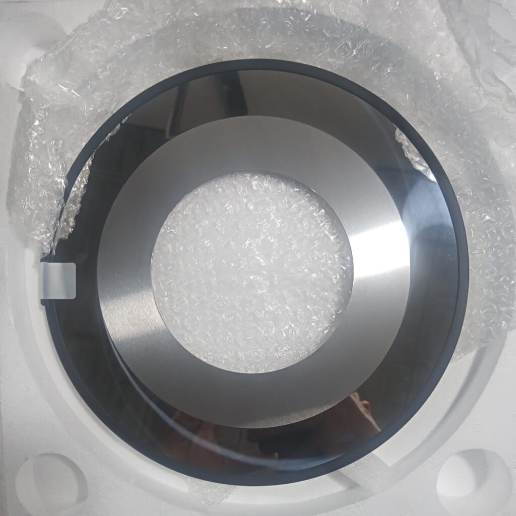
To sustain zero-dust slitting performance across multi-shift production, plant quality teams should adopt a structured inspection routine.
Portable Profilometer Inspection Protocol
- Measurement Location: Take three profilometer readings on the primary bevel flank at 120° intervals around the circular knife.
- Rejection Threshold: If average surface roughness exceeds Ra 0.18 µm or if individual peaks show Rz > 0.6 µm, schedule the blade set for precision re-lapping.
- Edge Inspection: Inspect the cutting edge under a 50x portable shop microscope. Any micro-chipping exceeding 0.005 mm in depth will act as a dust generator and requires regrinding.
Quantifying Dust Reduction: Measurement Protocols That Stand Up to Audit
To make dust-control claims defensible (rather than marketing assertions), converting plants should pair each improvement with structured evidence:
- Profilometer Measurement: Record Ra / Rz on the flank bevel before and after each blade change using a calibrated contact profilometer, averaging at least three traces 120° apart per ISO 4288.
- Edge Microscopy: Capture fixed-magnification (50x–200x) before/after images of the slit edge to document the transition from frayed, roughened edges to clean fracture faces.
- 집진 장치: Standardize dust sampling at a consistent location and method (for example, a fixed-area tape lift or gravimetric filter catch near the cut point) so results are comparable across blade sets and shifts.
This three-part protocol lets a plant attribute measured dust reduction to the correct variable combination — blade finish, geometry, or process setpoint — rather than overstating the effect of any single control.
Lapping and Precision Regrinding Guidelines
Regrinding superfinished blades on standard toolroom wheel grinders will destroy the Ra < 0.1 µm surface finish. This is consistent with supplier guidance that most converting applications require at least an eight RMS finish, while the highest-speed paper slitting lines demand a super finish of under one RMS to control dust.[4]
- Wheel Selection: Use fine vitrified CBN (Cubic Boron Nitride) wheels for PM steels or resin-bond diamond wheels (1200–2000 mesh) for tungsten carbide.
- Secondary Superfinishing: After primary angle grinding, pass the blades through a two-step diamond lapping process using diamond paste (1–3 µm grit) to restore the mirror finish.
- Demagnetization: Demagnetize all blades to under 2 Gauss after grinding. Residual magnetism attracts fine steel and iron dust, which gets carried directly into the web cut zone.
자주 묻는 질문(FAQ)
Q1: 고속 가공(Converting) 라인에서 슬리팅 분진이 발생하는 주요 원인은 무엇입니까?
슬리팅 분진은 주로 원단(Web)과 절삭 나이프 측면(Flank) 사이의 마찰로 인해 발생합니다. 나이프 측면에 거친 연삭 연삭 자국(Ra > 0.4 µm)이 남아 있으면, 이러한 미세한 돌기(Microscopic asperities)가 이송되는 원단 단면을 긁고 걸어 локально 미세 찢어짐(Micro-tearing)을 유발하며 미세 폴리머 및 섬유 분진을 방출합니다。
Q2: 분진 제어에 있어 절삭날의 날카로움 단독보다 나이프 측면 표면 조도(Ra)가 더 중요한 이유는 무엇입니까?
날카로움은 초기 전단 파단(Initial shear fracture)이 시작되는 용이성을 결정하지만, 고속 이송 중 원단 단면이 나이프를 지나 슬라이딩할 때의 거동을 지배하는 것은 측면 표면 조도입니다. 측면이 거친 면도날처럼 날카로운 나이프라도 미세 돌기 마찰(Micro-asperity drag)로 인해 원단 단면을 보풀세우고 다량의 분진을 발생시킵니다.
Q3: 제로 분진(Zero-dust) 필름 슬리팅을 위해 어떤 표면 조도 사양을 요청해야 합니까?
연포장 필름(BOPP, PET, PE), 산업용 부직포 및 코팅 호일의 경우, Ra < 0.1 µm (2–4 RMS) 및 Rz < 0.4 µm 사양의 슈퍼피니싱 경면 광택(Superfinished mirror polish)을 지정하십시오. 이는 Maxtor Metal이 고속 필름 및 부직포 가공 라인에 공급하는 모든 슬리팅 원형 나이프(Circular slitting knives)의 검수 기준(Acceptance threshold)으로 적용하는 동일한 사양입니다.
Q4: 기존 D2 공구강(SKD11)이 슈퍼피니싱(Superfinishing) 과정에서 경면 상태를 유지하지 못하는 이유는 무엇입니까?
기존 D2강은 거대한 조대 조형 크롬 탄화물(15–30 µm)을 함유하고 있습니다. 정밀 다이아몬드 랩핑(Diamond lapping) 시, 이러한 거대 탄화물이 강 매트릭스에서 탈락(탄화물 탈락 현상 / Carbide pull-out)하여 미세 피트(Micro-pits)를 형성하고, 이것이 이물질을 유착시켜 날 끝을 거칠게 만듭니다. 분말 야금강(PM-M4)이나 초미립자 텅스텐 카바이드(초경합금)는 서브미크론 수준의 탄화물 조직을 가져 이러한 문제를 방지합니다.
Q5: 축 방향 흔들림(Axial runout)은 슬리팅 분진 발생량에 어떤 영향을 미칩니까?
나이프 아버(Arbor)의 축 방향 흔들림(Axial runout)은 매 회전마다 상부 나이프와 하부 나이프 사이의 측면 간격(Side clearance)을 가변적으로 벌어지고 닫히게 만듭니다. 이러한 동적 흔들림은 원단 단면에 주기적인 마찰과 눌림(Cyclic rubbing and crushing)을 유발하여 주기적인 분진 폭발 및 버(Burrs / 버)를 발생시킵니다. 축 방향 흔들림은 ≤ 0.002 mm 이하로 유지되어야 합니다. Maxtor Metal은 완제품 슬리팅 원형 나이프 조립체(Circular slitting knife assemblies)의 배치 검사 기록에 이 측정 값을 필수 최종 검수 항목(Mandatory final gate)으로 기록합니다.
Q6: 슈퍼피니싱(Superfinished) 처리된 나이프를 일반 작업장 연삭기(Shop grinders)에서 재연삭(Re-sharpening)할 수 있습니까?
No. Standard grinding wheels leave coarse grinding marks (Ra 0.4–0.8 µm) that eliminate the benefits of a superfinish. Regrinding must be followed by a precision lapping process using fine CBN or diamond compounds (1–3 µm paste) to restore the Ra < 0.1 µm surface finish.
향후 과제: 슬리팅 라인을 제로 분진(Zero-Dust) 정밀 시스템으로 업그레이드하기
Eliminating slitting dust generation requires a systematic approach combining advanced tool metallurgy, superfinished surface metrology, and rigid machine alignment. By replacing standard commercial ground knives with superfinished (Ra < 0.1 µm) powder metallurgy circular blades, converting plants can eliminate web edge contamination, prevent optical defect triggers, and extend blade service life.
Maxtor Metal manufactures custom precision-ground circular slitting knives, shear blades, and bottom female bands engineered specifically to eliminate edge debris in high-speed converting. Every blade undergoes deep cryogenic treatment, ultra-fine diamond lapping, and complete material certification (EN 10204 Type 3.1) to guarantee consistent, zero-dust performance.
Quality is verified through an independently audited framework. The company is certified to ISO 9001 (quality management systems) and holds SGS third-party inspection certification, and production runs under an ISO-based “in-line” quality assurance regime with a multi-stage inspection gate (first-article, incoming material, in-process, and final inspection) on every order. These externally audited credentials give engineers a documented assurance trail that mirrors the root-cause discipline described throughout this report.
To review technical drawings or request custom knife grinding specifications for your converting line, contact the engineering team at Maxtor Metal.
참고문헌
- ISO 4287 — Geometrical product specifications (GPS) — Surface texture: Profile method — Terms, definitions and surface texture parameters; ISO 4288 — Rules and procedures for the assessment of surface texture.
- TAPPI (Technical Association of the Pulp and Paper Industry), Troubleshooting slitter blade wear — blade edge smoothness and ground surface finish criteria relevant to slit quality and dust generation on slitting lines; and TAPPI, Roll and Web Defect Terminology (Chapter 5: Slitter Defects), which classifies slitter dust and edge-quality defects such as fuzzy edge and dust in roll.
- Powder metallurgy high-speed and tool-steel grade documentation covering carbide size distribution and finish-holding capability: Z-M4 PM (PM-M4) Tooling Alloys Data Sheet, Zapp Precision Metals; 그리고 CPM 10V (AISI A11) Data Sheet, Crucible Industries.
- Industry converting references on knife surface-finish requirements: TAPPI, Troubleshooting slitter blade wear (ground surface finish not exceeding 16 micro-inches for utility slitting); and Converting Quarterly, Ten web defects due to slitting (very smooth knife surface finish — 8 RMS or lower — to reduce excessive dust creation).
- ISO 9001:2015 — Quality management systems — Requirements (ISO international standards catalog). Maxtor Metal’s quality management is certified to ISO 9001 and additionally verified through SGS third-party inspection.
- ISO 21940-11 — Mechanical vibration — Rotor balancing — Part 11: Procedures and tolerances for rotors with rigid behaviour, 그리고 ISO 20816-1 — Mechanical vibration — Measurement and evaluation of machine vibration, as applied to slitter arbor balancing and spindle condition.
- EN 10204 — Metallic products — Types of inspection documents (Type 3.1 mill certificate with batch-level material traceability). Official European standard; catalog/purchase entry via national standards body: NEN-EN 10204:2004 (Netherlands Standardization Institute).
- Maxtor Metal in-house quality assurance regime — ISO-based “in-line” inspection including first-article, incoming material, in-process, and final inspection on precision-ground circular slitting knives.
저자 소개
Jerry Chu — Technical Support Specialist, After-sales Service, Maxtor Metal
With 10 years of cross-industry application experience spanning paper, plastics crushing, metal slitting, and wood processing, Jerry specializes in diagnosing on-site cutting issues such as edge burr formation and excessive dust generation. He holds PMP and CMRP certifications, bringing project-management rigor and reliability-engineering perspective to blade selection and line optimization. For field troubleshooting support, contact Maxtor Metal’s after-sales engineering team.

 English
  Spanish
  Italian
  French
  Portuguese
  Russian
  German
  Arabic
  Hindi
Hindi  Vietnamese
  Indonesian
  Japanese
  Korean