

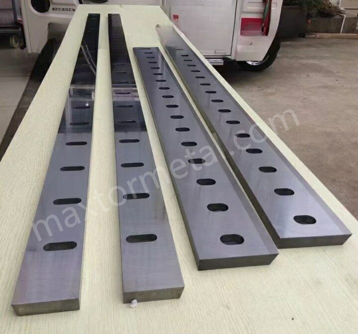
요약 (Quick Answer): 초경(텅스텐 카바イド) 인레이 전단 나이프는 AHSS 라인에서 기존 D2(SKD11) 나이프 대비 보통 2~3.5배의 절삭 수명을 제공합니다. ROI 창출의 핵심 동인은 단순히 나이프의 구매 단가가 아니라, 교체 작업(Changeover) 횟수 감소와 에지 불안정성으로 인한 스크랩(불량) 감소에 있습니다. 이 수명 증가 배수를 현장 생산에서 지속적으로 유지할 수 있는가를 결정하는 가장 중요한 두 가지 변수는 클리어런스 제어와 재연마 시 정밀한 나이프 형상 복원입니다.
초고속 AHSS/UHSS 가동 라인의 비가동 원인은 단순히 날물이 '절단하지 못해서'가 아닙니다. 날 끝의 치핑(날이 나감), 버(Burr) 높이의 변동, 부하 상태에서의 클리어런스 변화, 불균일한 재연마 형상과 같은 미세한 불안정 요소들이 손실로 누적되어 정지 시간(Downtime), 스크랩(불량品), 그리고 OEE(설비종합효율) 저하로 이어지기 때문입니다.
본 가이드북은 AHSS(초고장력강) 절단 가동이 가능한 전단 라인(Cut-to-Length) 및 길로틴 셔링 설비를 운용(또는 업그레이드) 중인 생산 및 보전 책임자, 공정 엔지니어, 기술 구매 담당자를 위해 작성되었습니다. 초경(카바이드) 인레이 나이프 도입을 검토할 때의 핵심은 단순히 상징적인 '수명 증가' 수치를 쫓는 것이 아닙니다. 강종 구성(Grade mix), 교체 작업(Changeover) 소요 시간, 재연마 회수 주기까지 종합적으로 반영했을 때도 유효한, 현장 재현성 높은 ROI 분석 모델을 구축하는 데 있습니다.
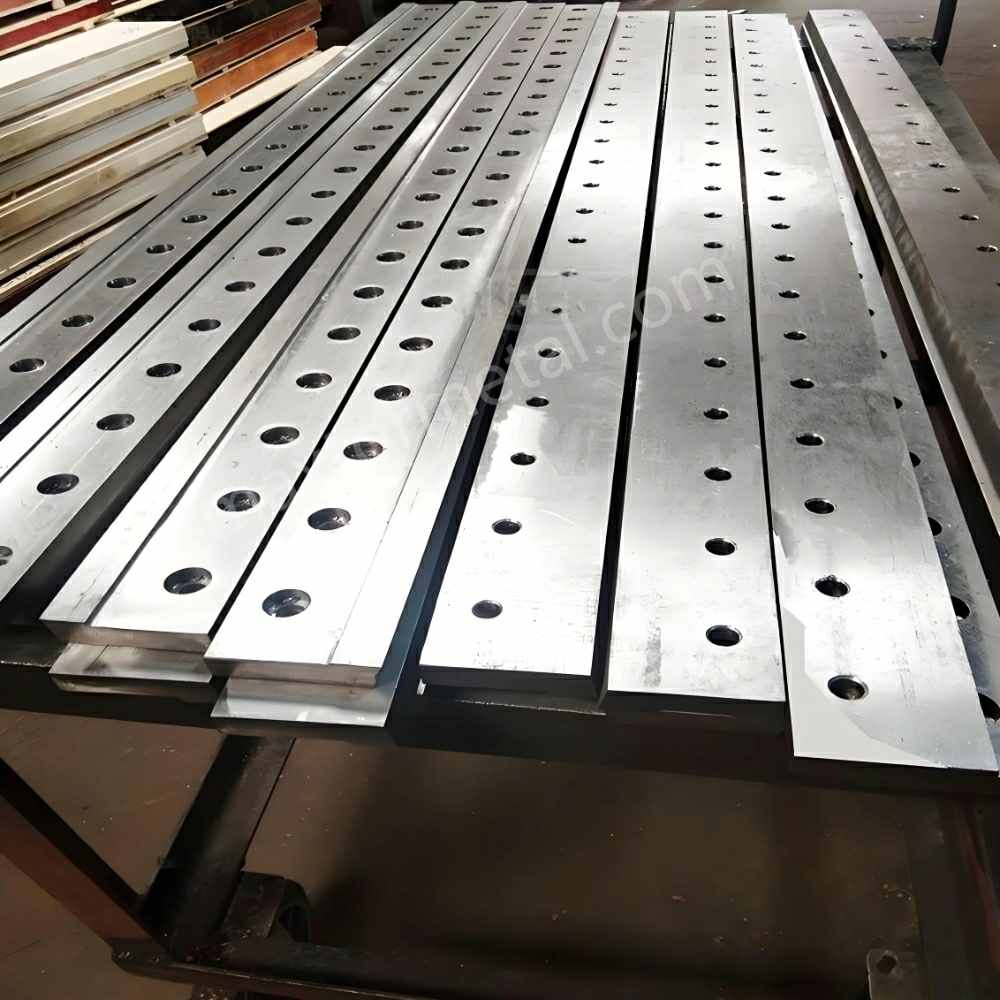
For reference on typical shear blade configurations and ordering formats, you can start with the Maxtor Metal shear blades page—then use the model and checkpoints below to validate fit and economics for your specific line.
- Who this guide is for and the AHSS/UHSS context
- What ultra-high-throughput changes in blade selection and maintenance
- How Tungsten Carbide Inlaid Shear Blades impact life, burr control, and TCO
AHSS(超高張力鋼)のせん断加工では、高強度に伴う発熱や凝着(アブレシブ/アドヒーシブ摩耗)の激化、ならびに設備系の公差累積(設備のたわみ・クランプ力・平行度)の影響増大により、適正な「切断条件の許容幅(Cutting window)」が極めて狭くなります。WorldAutoSteelのAHSS加工ガイドラインによると、適正クリアランス(刃先隙間)は鋼材強度に比例して拡大し、普通鋼(マイルドスチール)の板厚比約6%から、引張強度1400 MPaを超える超高張力鋼では約16%以上まで増大します。また、AHSSでは普通鋼と異なり「バリ高さ」が刃物摩耗の判定指标として信頼しにくいため、エッジ品質(剪断面形状)の直接監視がより重要であると指摘されています。
초고속 생산(Ultra-high throughput) 환경에서 변하는 핵심은 단순합니다. 단순히 '더 단단한' 나이프만으로는 부족합니다. 정기 정비 주기 사이 동안 절삭날의 안정성을 유지할 수 있는 시스템 — 즉, 예측 가능한 재연마 주기, 정밀하게 제어된 날 끝 처리(Edge Prep), 그리고 로트(Batch) 간 형상 변형을 방지하는 QC 피드백 루프가 구축되어야 합니다.
Tungsten carbide inlaid shear blades are often evaluated for three practical reasons:
- Wear-life stability at the cutting edge (especially when grades and surface conditions vary)
- Burr control over time (less drift as the edge dulls)
- 총 소유 비용(TCO) 절감 when you account for changeovers, regrinds, and scrap
Engineering Note: Tungsten carbide inlaid shear blades are precision cutting tools in which a brazed tungsten carbide edge is integrated into a D2 or H13 alloy steel body, combining the toughness of tool steel with the wear resistance of carbide at the cutting face. For AHSS and UHSS shearing lines, this construction extends edge stability between regrind events and reduces burr drift under variable grade and surface conditions—provided clearance control, alignment, and regrind geometry restoration are maintained. [→ See Maxtor Metal shear blade technical overview]
초경(텅스텐 카바이드) 인레이 전단 나이프 성능 벤치마크
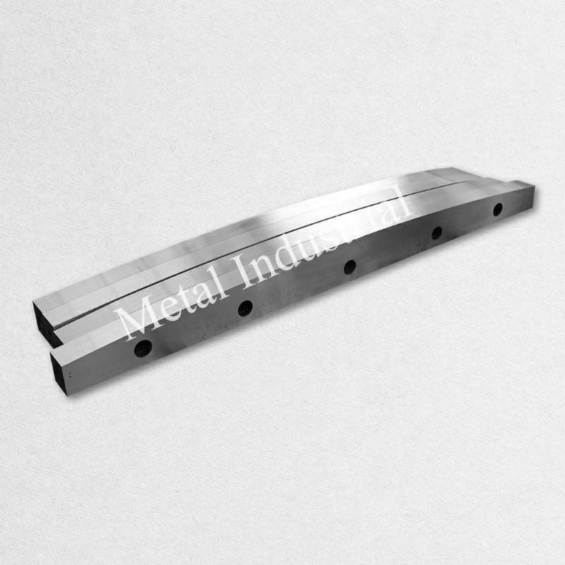
Life multipliers vs D2/high-vanadium steels
Carbide-inlaid blades usually earn their ROI when your current failure mode is edge breakdown (micro-chipping, accelerated wear at the edge, burr instability) rather than a one-off mechanical crash.
Instead of relying on a universal “X-times life” claim, benchmark with two plant-measurable indicators:
- Meters (or tons) per sharp edge until your quality trigger is reached
- Time-to-trigger stability across grade mix (the same blade shouldn’t behave like two different tools when you switch from HSLA to AHSS)
A useful way to compare against D2 or high-vanadium tool steels is to run a controlled pilot across your top 2–3 grades and one “worst-case” condition (coated material, higher surface scale, or your most burr-sensitive downstream process). The ROI model later in this guide will let you convert any observed life ratio into cost per meter/ton.
Inlay depth, edge finish, and micro-hone targets
For AHSS lines, the edge does two jobs at once: it has to resist abrasive/adhesive wear while staying tough enough to avoid brittle chipping.
Three parameters tend to dominate outcomes:
- Inlay depth: Deeper inlay generally supports more total regrinds before the inlay limit is reached.
- Edge finish: Surface finish at the cutting face influences friction, heat generation, and adhesion.
- Micro-hone: A controlled micro-hone reduces “knife-edge fragility” and can improve edge stability, especially when clearance isn’t perfectly uniform across the length.
The best target values depend on thickness, strength, and whether your line is burr-limited or geometry-limited. The key is to define acceptance criteria (see the QC section) so regrinds don’t quietly drift the micro-hone and change your burr behavior.
As a general reference, inlay widths in the 3–6 mm range are common for guillotine and CTL shear blades; inlay depth is governed by blade thickness allowance and the total number of regrind cycles required.
At Maxtor Metal, carbide-inlaid shear blades are manufactured with documented inlay geometry and post-grind surface finish records, ensuring the micro-hone and cutting face specifications established at the factory are traceable through the regrind cycle.
Regrind interval triggers and typical counts
On mild steels, burr height often rises with wear and can be a straightforward trigger. On AHSS, WorldAutoSteel’s AHSS Guidelines note burr height may remain relatively constant even as tooling wears, which is why a broader trigger set is safer.
사용 two triggers: one for edge quality and one for risk.
- Edge-quality triggers (choose what your downstream process punishes most):
- fracture zone roughness drift
- uneven burnish/fracture transition
- visible micro-chipping or line marks that correlate with burr drift
- Risk triggers:
- rising changeover time due to alignment fight
- increasing adjustment frequency to hold tolerance
- increased scrap events clustered after grade switches
These trigger sets map directly to common search queries like shear blade regrind interval and help you standardize when operators should intervene.
Typical total regrind counts vary with inlay depth, blade thickness allowance, and how tightly geometry is restored each cycle. The practical point: you should be able to predict an expected cycle count band before you commit, because the ROI model depends on it.
세팅 및 파손·불량 제어
Setup is where most ROI is won or lost. A premium blade running in a drifting setup becomes an expensive consumable.
If your top complaint is burr control in AHSS shearing drifting over a run, the two levers that usually matter most are (1) holding clearance uniformity end-to-end and (2) keeping edge prep consistent after each regrind. Sample edge-zone appearance on a fixed cadence (by coil count or shift) and correlate it with adjustment frequency and regrind events.
Clearance targets for thin AHSS and stainless
For thin AHSS and stainless, think in clearance as a percent of thickness, then verify it stays consistent end-to-end under real clamping.
WorldAutoSteel’s AHSS Guidelines discuss that clearance commonly increases with strength (from ~6% to ~16%+ in higher-strength regimes), and also caution that both too-small and too-large clearances create distinct failure modes.
Practical targets to start from (then validate with test cuts and edge inspection):
- AHSS shearing blade clearance: start in the 10–16% of thickness range for higher strengths, and adjust based on edge appearance and cracking sensitivity.
- Stainless (thin gauges): often needs higher clearance than mild steel to avoid double-shear and excessive work hardening; validate with edge zone appearance and burr behavior.
핵심 요점: In AHSS, don’t treat burr height alone as your “clearance is right” signal—monitor the full cut-edge zone behavior and stability over time.
Alignment, rake angle, and uniform clamping
If you only implement one discipline change for AHSS, make it this: treat parallelism and clamping uniformity as quality variables, not maintenance variables.
- Alignment: verify parallelism at multiple points along the blade length, not just at the ends.
- Rake angle: choose a rake strategy consistent with your material mix; extreme angles can reduce force but can also change deformation patterns on thin materials.
- Clamping: non-uniform clamping creates local clearance spikes; those spikes tend to be where chipping starts and where burr drift becomes “mysterious.”
Heat, adhesion, and edge-prep strategies
AHSS and stainless amplify two problems: heat 그리고 부착.
- Heat: higher load plus friction can soften local zones and accelerate wear; heat also amplifies micro-chipping risk when the edge is too sharp.
- Adhesion: stainless in particular can “pick up” and smear; that changes effective clearance and can cause edge marking.
Edge-prep strategies that tend to stabilize behavior:
- use a controlled micro-hone rather than a fragile razor edge
- keep cutting faces consistent in finish after each regrind
- if adhesion is the dominant issue, focus on surface condition and cleaning discipline (adhesion layers become a geometry change)
재연마 프로토콜 및 품질 관리(QC) 기준
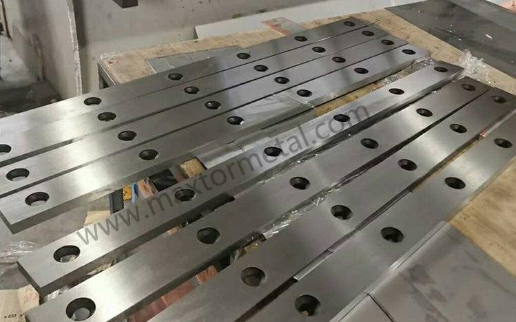
Inlay limits, regrind steps, and total allowable cycles
Carbide inlay changes the regrind question from “how many times can we sharpen?” to “how many times can we sharpen before we compromise the inlay system?”
Your protocol should define:
- minimum remaining inlay depth (stop point)
- maximum allowable thickness loss per regrind
- how you preserve the edge prep (micro-hone) across cycles
- a rule for when a blade is “regrindable” vs “scrap” (cracks, braze integrity concerns, geometry loss)
For the shim calculation method used to compensate for thickness loss after each regrind cycle, see the regrinding thickness reduction compensation and shim stack guide.
Geometry restoration, surface finish (Ra), and acceptance criteria
Regrind ROI only works if geometry restoration is disciplined.
Recommended acceptance criteria categories:
- Geometry
- straightness along the cutting edge
- parallelism across the length
- consistent bevel geometry (no “soft corner” drift)
- 표면 조도
- cutting face finish should be controlled and repeatable (track Ra or an equivalent surface-finish measure)
- Edge condition
- no micro-chipping beyond your defined threshold
- consistent micro-hone (do not allow “sharper every time” drift)
Maxtor Metal’s post-grind acceptance protocol covers all three categories above—geometry, surface finish, and edge condition—with traceable inspection records returned with each regrind batch.
For documentation of edge requirements on drawings, the standard for indicating undefined edge requirements in technical product documentation is ISO 13715:2017. Even if you don’t use the symbology directly, aligning your internal acceptance language to a recognized standard reduces ambiguity between shifts, suppliers, and regrind vendors.
Maxtor Metal supports carbide-inlaid blade manufacturing with in-process QC checks and can provide regrind service with traceable inspection records, which helps keep geometry and batch consistency under control.
Documentation, MTCs, and batch consistency checks
For AHSS lines, procurement risk is often hidden in variation: the same part number behaves differently across batches.
A practical documentation pack for each batch should include:
- MTC / material traceability for the base body and inlay material where applicable
- hardness / heat-treatment evidence where relevant
- inspection reports for key dimensions (thickness, straightness, parallelism)
- regrind history log (cycle count, removed stock, post-grind inspection)
This doesn’t have to be bureaucratic. The point is to make root-cause work fast when you see burr drift or chipping: you can separate setup issues from batch variation.
TCO(총소유비용) 및 ROI(투자대비효과) 분석 모델
Inputs, formulas, and amortization logic
The TCO structure below reflects how Maxtor Metal frames cost conversations with high-throughput AHSS lines: total cost per meter, not blade price.
A useful ROI model turns “blade life” into cost per meter (or 톤당 비용) and adds the costs that typically dominate in high-throughput lines: downtime and scrap.
This is the backbone for a practical total cost of ownership for shear blades comparison, because it forces every assumption (life, regrinds, changeover minutes) into the same unit.
Define these inputs:
C_blade: purchase cost of one blade setN_edges: usable edges per set (including flips/rotations if applicable)L_edge: meters (or tons) per edge between regrinds/replacementsN_regrinds: total regrinds achievable before scrap (bounded by inlay limit + geometry tolerance)C_regrind: cost per regrind cycleT_change: changeover time per event (hours)C_downtime: fully-loaded downtime cost per hourC_scrap: scrap/rework cost per ton (or per meter)S_scrap: scrap rate attributable to cut-edge instability (as a fraction)
A simple amortization structure:
- Blade amortization per meter
Copy-and-paste ROI calculator template
If you want a template that’s easy to move into Excel, start with this table and fill in your own line data. Keep units consistent (meters 또는 tons) across every row.
| 입력 | 상징 | 당신의 가치 | Units / notes |
|---|---|---|---|
| Blade set purchase cost | C_blade | $ per set | |
| Usable edges per set | N_edges | count (include flips/rotations) | |
| Life per edge to trigger | L_edge | meters/edge or tons/edge | |
| Total regrinds before scrap | N_regrinds | count (bounded by inlay + tolerances) | |
| Regrind cost per cycle | C_regrind | $ per regrind | |
| Changeover time per event | T_change | hours/event | |
| Downtime cost | C_downtime | $/hour (fully loaded) | |
| Scrap cost | C_scrap | $/ton or $/meter | |
| Scrap rate due to cut-edge instability | S_scrap | fraction (e.g., 0.009 = 0.9%) | |
| 산출 | 공식 | 결과 | 노트 |
| — | — | — | — |
| Total life per blade set | Total_m | N_edges × L_edge × (N_regrinds + 1) | Use meters or tons consistently |
| Blade amortization per unit | Cost_blade_per_m | C_blade / Total_m | $/meter or $/ton |
| Regrind cost per unit | Cost_regrind_per_m | (C_regrind × N_regrinds) / Total_m | $/meter or $/ton |
| Downtime cost per unit | Cost_down_per_m | (T_change × C_downtime × (N_regrinds + 1)) / Total_m | Simplified; add extra events if unplanned |
| Scrap cost per unit | Cost_scrap_per_m | S_scrap × C_scrap | Convert units if needed |
| Total cost per unit | TCO_per_m | Sum of all costs above | Compare baseline vs carbide-inlaid |
This layout makes it easy to run the same model for baseline and carbide-inlaid scenarios, then compute deltas (TCO reduction, payback period, and ROI).
Cost_blade_per_m = C_blade / (N_edges × L_edge × (N_regrinds + 1))- Regrind cost per meter
Cost_regrind_per_m = (C_regrind × N_regrinds) / (N_edges × L_edge × (N_regrinds + 1))
- Downtime cost per meter (changeovers + regrinds)
Cost_down_per_m = (T_change × C_downtime × Events_total) / Total_meters
Then add scrap:
Cost_scrap_per_m = S_scrap × C_scrap(convert units consistently)
The ROI comparison is the delta:
ROI = (TCO_baseline - TCO_carbide) / Investment_delta
Example cost per meter/ton with placeholders
Below is a worked example using sample values to show how the math behaves. Replace the numbers with your own line data.
Assume:
C_blade = $6,000per setN_edges = 2L_edge = 200,000 mN_regrinds = 6C_regrind = $450
Total meters per set across life:
Total_m = N_edges × L_edge × (N_regrinds + 1) = 2 × 200,000 × 7 = 2,800,000 m- Blade amortization per meter:
$6,000 / 2,800,000 = $0.00214/m
- Regrind cost per meter:
($450 × 6) / 2,800,000 = $0.00096/m
If your dominant cost is downtime, you’ll see ROI swing heavily with changeover time.
Example downtime inputs:
T_change = 0.5 hoursper eventC_downtime = $3,000/hourEvents_total = 7(initial + 6 regrinds)
Downtime cost per meter:
($3,000 × 0.5 × 7) / 2,800,000 = $0.00375/m
This simple example shows why “unit blade price” often isn’t the lever—changeover hours and stability events are.
Sensitivity to gap control, grade mix, and regrind SLA
Three sensitivity levers usually dominate:
- Gap control (clearance uniformity)
- Poor gap control can erase life gains by triggering chipping and forcing early regrinds.
- Grade mix (strength + surface condition)
- If your schedule shifts toward higher-strength AHSS or more abrasive surface conditions, edge stability becomes more valuable.
- Regrind SLA (turnaround + consistency)
- Slow or inconsistent regrinds increase spare inventory requirements and increase the chance of geometry drift.
If you want one “finance-friendly” sensitivity output, model TCO under three scenarios (conservative / expected / optimistic) by varying only:
L_edge(life)T_change(changeover time)S_scrap(scrap attributable to edge instability)
A clean way to present sensitivity—without overfitting—is to vary only the assumptions that typically dominate TCO for high-throughput lines.
| 대본 | Life per edge L_edge | Changeover time T_change | Edge-instability scrap S_scrap | What it represents |
|---|---|---|---|---|
| Conservative | lower-bound of your pilot band | higher-bound of your observed changeover | higher-bound of edge-related scrap | Setup drift, rougher surface condition, slower regrind turnaround |
| Expected | median of pilot band | median changeover | median scrap attribution | Normal operating cadence and grade mix |
| Optimistic | upper-bound of pilot band | lower-bound changeover (best-practice SOP) | lower-bound scrap attribution | Tight clearance control + consistent regrinds + stable material |
When you present the result, show ranges (not a single point estimate) for TCO per meter/ton and downtime minutes avoided. This usually makes the business case more credible than a single ROI number.
현장 적용 및 가동 플레이북
SOPs for changeover, inspection, and regrind logistics
The three SOPs below apply across all pilot contexts and should be locked before you scale to full production.
For a complete measurement-based rotation and regrind decision SOP applicable to guillotine shear blades—including burr threshold bands, edge-use sequence, and audit-ready log templates—see the 4-edge reversible blade rotation schedule and regrind criteria SOP.
필드 테스트 결과: 3가지 익명화 사례 요약
The fastest way to defend an ROI decision is to capture a small, controlled pilot and report results in the same units your plant already tracks: coils between regrinds, burr stability, setup interventions, scrap/rework, and OEE minutes.
Below are three anonymized pilots that illustrate where carbide-inlaid blades tend to pay back first. Use them as structure, not as a promise—your results will depend on grade mix, clearance control, clamping repeatability, and regrind consistency.
Pilot Case 1 — AHSS CTL on DP980
Context
- Material: DP980 (980–1000 MPa)
- Thickness: 1.2–2.0 mm
- Line: Coil-to-Length (CTL)
- Coil condition: Pickled & Oiled, light mill scale+
- Blade: Carbide-inlaid blade: D2 body + brazed ultra-fine WC edge, supplied by Maxtor Metal
Baseline vs carbide-inlaid configuration
- Baseline blade: D2 tool steel, 60–61 HRC
- Carbide-inlaid blade: D2 body (59–60 HRC) + brazed ultra-fine WC edge
- Carbide width: 4 mm
- Edge hardness: ~89 HRA
Triggers and measurement
- Triggers after ~40–50 coils on baseline:
- burr height approaching 0.10 mm
- increasing blade clearance adjustment frequency
- more frequent first-piece rechecks
- Measurement sequence:
- per coil: burr height measured at left/center/right using a 50× toolmaker microscope
- every 10 coils: log max burr, clearance, and edge radius
Pilot results
| KPI | Baseline D2 | WC inlaid |
|---|---|---|
| 블레이드 라이프 | 1.0× | 2.9× |
| Coils between regrinds | 48 | 138 |
| Average burr | 0.082 mm | 0.039 mm |
| Unplanned setup events | 5/month | 2/month |
| 권투 시합 | 1.8% | 0.9% |
| OEE | 84.1% | 87.6% |
| Regrind SLA | — | 5 working days |
What this pilot taught
- DP980’s abrasiveness made edge-wear stability the primary lever.
- Keeping the same clearance settings used for D2 initially caused localized micro-chipping; a small clearance optimization restored stable behavior.
Pilot Case 2 — Guillotine line with heavy mill scale
Context
- Material: Hot rolled AHSS
- Thickness: 4–8 mm
- Line: Hydraulic guillotine
- Surface: heavy mill scale
- Blade: Carbide-inlaid blade: H13 body + brazed ultra-fine WC edge, supplied by Maxtor Metal
Baseline vs carbide-inlaid configuration
- Baseline blade: modified H13
- Carbide-inlaid blade: H13 body + brazed tungsten carbide edge; double-tempered
Triggers and measurement
- Scale-driven wear increased burr and forced frequent setup adjustments.
- Measurement:
- per shift: check burr, edge radius, and blade temperature
- weekly: verify straightness and flatness
Pilot results
| KPI | 전에 | 후에 |
|---|---|---|
| 블레이드 라이프 | 1.0× | 2.1× |
| 매달 칼날 교체 | 4 | 2 |
| Setup time | 150 min/month | 70 min/month |
| 재작업 | 2.4% | 1.3% |
| Edge chipping | occasional | significantly reduced |
| Regrind SLA | — | 7 calendar days |
What this pilot taught
- Mill scale remained the dominant wear source. Carbide improved wear resistance, but without scale removal the life multiplier was lower than in pickled/oiled conditions.
Pilot Case 3 — High-volume automotive CTL
Context
- Material: CP780 + DP780
- Thickness: 1.6–2.5 mm
- Line: high-speed CTL
- Annual output: >60,000 t
- Blade: Carbide-inlaid blade: D2 body + brazed ultra-fine WC edge, supplied by Maxtor Metal
Baseline vs carbide-inlaid configuration
- Baseline blade: premium D2
- Carbide specification: fine-grain WC, vacuum brazed
- Surface finish target after grinding: Ra ≤ 0.2 μm
Triggers and measurement
- High cadence required planned weekly stoppages; burr began to affect downstream weld quality.
- Measurement:
- first-piece: burr height
- every 20 coils: microscope check, clearance, edge radius
- every regrind: flatness, parallelism, thickness
Pilot results
| KPI | 전에 | 후에 |
|---|---|---|
| 블레이드 라이프 | 1.0× | 3.4× |
| Regrind interval | 2주 | 7 weeks |
| Max burr | 0.11 mm | 0.05 mm |
| 계획된 점검 시간 | 9 h/month | 4 h/month |
| Customer edge claims | 3/quarter | 0–1/quarter |
| Estimated TCO | baseline | ~18% reduction(blade amortization + regrind + changeover inputs; calculated using TCO model above) |
| Regrind SLA | — | 3–4 working days |
What this pilot taught
- A fixed rotation + regrind schedule plus reinstall checks (parallelism + clearance) prevented installation variation from masking tooling differences. The ~18% TCO reduction was driven primarily by the regrind interval extension (2 weeks → 7 weeks) and the reduction in planned downtime (9 h/month → 4 h/month), with blade amortization contributing a smaller share at this throughput level.
A simple pilot record you can copy
Capture the pilot in one sheet so finance and production speak the same language:
- grade(s) + thickness range + surface condition
- meters/tons/coils to trigger (edge-quality + risk trigger)
- changeover minutes per event (median and worst 10%)
- scrap/rework attributable to cut-edge instability
- regrind SLA (days) and post-regrind acceptance results
- notes on clearance settings, clamping repeatability, and any setup changes during the pilot
Treat the blade as part of a controlled process, not a consumable:
- Changeover SOP: torque pattern, clamp inspection, parallelism verification points
- Inspection SOP: define the edge-quality triggers that force action (not just “looks dull”)
- Regrind logistics SOP: tagging, cycle counting, and post-regrind acceptance checks
Data capture, dashboards, and KPIs for OEE and quality
If you don’t measure it, you can’t defend the ROI.
Practical KPIs:
- meters/tons per edge to trigger
- regrind cycle count distribution (are you consistently hitting your expected band?)
- changeover time (median + worst 10%)
- scrap/rework events tied to burr/edge issues
- OEE loss minutes attributed to shearing (not generic “maintenance”)
Dashboards don’t have to be complex. A simple weekly report that ties regrind events to OEE minutes and scrap is enough to validate whether carbide-inlaid blades are paying back.
Supplier evaluation and SLA criteria for carbide tips and brazing
For carbide-inlaid blades, supplier evaluation should focus on repeatability as much as materials.
Key criteria:
- inlay integrity and consistency (process control and inspection evidence)
- documented geometry tolerances and inspection methods
- regrind capability and stated limits (what is the stop rule?)
- SLA clarity: turnaround time, rush options, and consistency commitments
- traceability: MTCs and batch records
Before committing to carbide-inlaid blades, confirm that the failure driver is not a correctable material-selection issue at the tool steel level. If your current blade is conventional EAF-melted D2 with coarse carbide banding rather than ESR-refined stock, a grade or refining practice change may extend life before a full carbide upgrade is needed. The comparative framework — carbide microstructure, failure mode analysis, and hardness recommendations for D2 vs SKD11 — is covered in the D2 vs SKD11 tool steel selection guide for shearing blades.
FAQs:
Q: 길로틴 셔링기에서 AHSS(초고장력강) 전단 시 초기 적정 클리어런스는 얼마로 설정해야 합니까?
A: 소재 두께 대비 백분율(%)로 초기 클리어런스를 설정한 후, 시범 절단(Test cut) 및 단면 검사를 통해 최종 검증하십시오. WorldAutoSteel의 AHSS 가이드라인에 따르면 클리어런스는 연강(~6%) 대비 초고강도 영역에서 최대 ~16% 이상까지 증가합니다. 대부분의 AHSS 절단 현장에서는 강종과 두께에 따라 최종적으로 10~16% 범위 내에서 설정됩니다.
Q: AHSS(초고장력강) 전단에서 '버(Burr) 높이'가 나이프 마모 지표로 적합하지 않은 이유는 무엇입니까?
A: AHSS는 날 끝이 마모되더라도 버 높이가 относительно 일정하게 유지될 수 있기 때문입니다. 현장에서는 버 높이 대신 전단면 상태(광택면/파단면의 균일성), 날 끝의 미세 치핑(Micro-chipping), 강종 변경 시의 절단 품질 유지 여부를 기준 삼아 교체/재연마 조치를 취하는 것이 훨씬 안전합니다.
Q: 텅스텐 카바이드(초경) 인레이 전단 나이프를 사용하면 항상 버(Burr)가 줄어듭니까?
A: 항상 그렇지는 않습니다. 날 상태를 더 오래 유지하여 장기적인 버의 안정성을 향상시킬 수는 있지만, 버의 발생은 여전히 클리어런스 균일성, 정렬(Alignment), 클램핑, 그리고 재연마 시의 형상 복원 정밀도에 의해 크게 좌우됩니다.
Q: 초경(카바이드) 인레이 전단 나이프는 몇 번이나 재연마할 수 있습니까?
A: 카바이드 인레이의 깊이, 1회 연마당 허용 두께 손실량, 그리고 재연마 시의 형상 복원 정밀도에 따라 달라집니다. 잔여 인레이 두께, 형상 공차, 구조적 균열/손상 위험 징후를 바탕으로 명확한 '연마 한계 기준(Stop Rule)'을 설정한 후, 해당 기준 범위 대비 실제 재연마 횟수를 추적·관리하십시오.
Q: AHSS(초고장력강)용 전단 나이프 구매 시 요구해야 하는 QC(품질 관리) 서류는 무엇입니까?
A: 최소한: 자재 추적성 성적서(MTC/ミルシート), 핵심 치수(두께/직선도/평행도) 검사 성적서, 그리고 재연마 이력 관리 로그가 필요합니다. 도면상에 날 끝/에지 요구사항을 명시할 때 ISO 13715:2017 표준을 참조하면 사양의 모호성을 크게 줄일 수 있습니다.
Q: 전단 나이프의 '미터당 가공 비용(Cost per meter)'은 어떻게 계산합니까?
A: TCO(총소유비용)를 나이프 감가상각비 + 재연마 비용 + 정지 손실(다운タイム) + 스크랩/OEE 항목으로 세분화하십시오. Total_m = N_날수 × L_날길이 × (N_재연마횟수 + 1) 공식을 사용하여 총 전단 미터수(Total_m)를 구한 뒤, 각 비용 항목을 Total_m으로 나눕니다. 그 후 기본 사양(Baseline)과 카바이드 인레이 사양의 시나리오를 비교 검증하십시오.
Q: 나이프 재질 선정 외에 가장 큰 ROI(투자 대비 효과) 개선 요소는 무엇입니까?
A: 교체/교체 작업 시간(Changeover time)과 안정성 저해 이벤트(비계획 재연마, 수동 미세 조정, 스크랩 폭증)의 발생 횟수입니다. 카바이드 인레이 나이프를 통해 현장 개입 횟수를 줄일 수 있다면, ROI는 보통 이 지점에서 가장 먼저 입증됩니다.
Q: 절단면 품질(Cut-edge quality)과 후공정 성형성 리스크(Formability risk)를 어떻게 연계하여 평가합니까?
A: 구멍 확장 시험(Hole expansion test)과 같은 표준 기반 시험은 박판 및 스트립 자재의 에지 균열 감도(Edge crack sensitivity)를 정량화하도록 설계되었습니다.
참고 규격: ISO 16630:2017참조. 이 표준은 에지 성형성(Edge formability)을 평가하기 위해 널리 사용되는 '구멍 확장 시험 방법(Hole expansion test method)'을 정의합니다.
결론
Decision checkpoints you can defend
Use this as a practical “go/no-go” lens before you scale carbide-inlaid blades across an AHSS/UHSS line:
- Is your constraint intervention-driven? If downtime minutes and stability events (unplanned regrinds, clearance adjustments, scrap bursts) dominate cost, carbide-inlaid blades usually have a clear path to payback.
- Can you hold clearance and clamping repeatably? If parallelism and uniform clamping drift, a premium edge becomes an expensive consumable.
- Do you have a repeatable regrind loop? ROI depends on consistent geometry restoration (flatness/parallelism/edge prep) and a regrind SLA that matches your production cadence.
- Do your triggers match AHSS reality? In AHSS, burr height alone can be misleading—combine an edge-quality trigger with a risk trigger so interventions happen before scrap spikes.
- Can you trace performance back to batch + regrind cycle? Without serial/batch traceability, it’s hard to separate setup drift from batch variation.
Maxtor Metal can provide regrind acceptance criteria templates and traceability documentation aligned to the QC structure in this guide.
Next steps for implementation
- Run a short, controlled pilot across your top 2–3 grades plus one worst-case condition (coating, scale, or burr-sensitive downstream operation). Log coils/tons/meters to trigger, changeover minutes, and any edge-related scrap.
- Convert pilot data into cost per meter/ton using the TCO model (amortization + regrind + downtime + scrap). Build conservative/expected/optimistic scenarios for the assumptions that actually move the needle.
- Lock your regrind and QC acceptance criteria (geometry, surface finish, micro-hone/edge prep, traceability) so the tool you pilot is the tool you can reorder.
RFQ and drawing checklist for carbide-inlaid shear blades
Send this checklist with your RFQ to reduce back-and-forth and avoid specification gaps:
- Application and line context: CTL or guillotine; coil/sheet thickness range; grade mix; surface condition (pickled/oiled, scale, coated)
- Blade set details: quantity per set; usable edges/rotations; existing part number; mounting hole pattern and tolerances
- Geometry requirements: length/width/thickness; straightness; flatness; parallelism; bevel angle(s); rake strategy (if applicable)
- Edge prep requirements: micro-hone target (or allowed range); surface finish target on cutting faces (Ra, if specified)
- Carbide inlay requirements: inlay width/depth; braze method expectations; stop rule for minimum remaining inlay
- Operating targets: clearance % starting point and adjustment practice; burr threshold (if used); inspection cadence
- Documentation pack: EN 10204 3.1 / MTC with heat number traceability; hardness reports (HRC/HRA); dimensional inspection report; heat-treatment record; regrind history log
- Service requirements: regrind SLA (days); post-regrind acceptance checks; serialization/batch labeling
If your line is limited by burr drift, chipping, and changeover minutes, carbide-inlaid blades plus disciplined setup/QC can be a financially defensible upgrade. If your biggest losses come from upstream variability or non-repeatable clamping, fix those first—then reassess using the same pilot-and-TCO framework.
작가: Nancy Wu, Senior Manufacturing Engineer, PE (Production Engineering), Maxtor Metal (12 years in industrial blade selection, CNC grinding programming, and regrind process control).
신임장: SME – CMfgE; PMP; Six Sigma Black Belt; ASM International Certifications.
Materials expertise: D2, M2, H13, powder metallurgy steels, and tungsten carbide (manufacturing characteristics and coating behavior).
Methodology: This guide combines established AHSS shearing guidance (including WorldAutoSteel AHSS resources) with plant-facing ROI accounting (cost per meter/ton) and field pilot reporting. Pilot performance should be validated on your own line using a controlled grade mix, defined triggers, and consistent measurement routines.
Quality & traceability signals you can request from Maxtor Metal (example documentation pack)
- Incoming inspection: EN 10204 3.1 / MTC, heat number traceability, PMI when required, chemistry spot checks, optional ultrasonic testing for large billets
- Heat treatment: vacuum heat treatment, multiple temper cycles, batch hardness sampling and uniformity records (HRC for body; HRA for carbide)
- Dimensional inspection: thickness/width/length, flatness, straightness, parallelism, hole position, edge angle; full-length checks for long shear blades
- Surface and edge: Ra (surface roughness) records when specified, grinding pattern inspection, edge honing inspection, 100% visual inspection
- Equipment commonly used: digital micrometers, height gauge, granite surface plate, dial indicator, surface roughness tester, Rockwell hardness tester, optical microscope, precision straightedge; CMM spot checks for larger parts
- Shipping reports: dimensional inspection report, hardness report, first article inspection (FAI) when required, material certificate, heat-treatment certificate, surface finish record (per customer requirement)
- Traceability: unique blade serial number, batch number, material heat number, grinding batch, heat-treatment batch, record retention (e.g., ≥5 years)
- NCR controls: quarantine and NCR record, root-cause (5-Why/fishbone), MRB disposition (rework/remake/scrap), CAPA, and full re-inspection after rework with updated traceability

 English
  Spanish
  Italian
  French
  Portuguese
  Russian
  German
  Arabic
  Hindi
Hindi  Vietnamese
  Indonesian
  Japanese
  Korean