
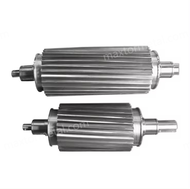
A cantilevered pelletizer rotor on a water‑strand line uses a swing‑open or slide‑open cutting chamber so the rotor, bed knife, and feed area are exposed in seconds, without dismantling the front bearing set. Fewer fasteners and components stand between you and the cutting zone, which means faster cleaning, quicker knife swaps, and less time for coloured residues to bleed into the next run. In short, it helps you get from colour A to colour B sooner, with a lower risk of streaks, tails, and fines.
In this guide you’ll learn how a cantilevered access design saves time, what to look for when selecting one, how to set gaps and maintain the cutter, and what documents to request from knife suppliers to keep QA airtight. We’ll refer to the exact term “cantilevered pelletizer rotor” throughout to align with common search intent.
Những điểm chính cần ghi nhớ
- Swing‑open access cuts steps during colour change and shortens exposure of wet parts, reducing cross‑contamination.
- Start with conservative knife‑to‑bed clearances (0.05–0.20 mm) and verify by pellet quality; record settings and outcomes for repeatability.
- Prioritise corrosion‑resistant bearings/seals and proper strand drying to stabilise pellets and lower fines.
- Ask suppliers for traceable material, heat‑treat, hardness (ASTM E18/ISO 6508‑1), and dimensional reports.
Why cantilevered rotors on water‑strand lines
Faster access, fewer steps
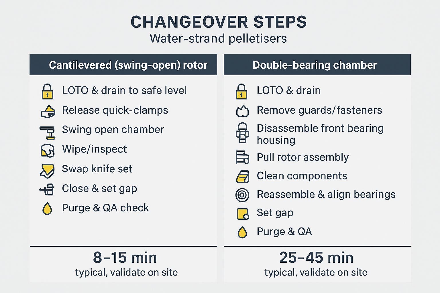
Compared with double‑bearing chambers that require guard removal, housing disassembly, and bearing realignment, a cantilevered access design uses quick‑release clamps and a hinged or rail‑guided front to expose the rotor and bed knife. In practice, a cantilevered pelletizer rotor helps operators move directly from LOTO to knife access with minimal tools, which is the core driver of faster changeovers. Several OEM strand pelletisers emphasise tool‑less or rapid entry to the cutting zone, reducing maintenance and cleaning time; for example, MAAG’s training and brochures highlight pivoting or sliding housings designed to minimise downtime, as seen on the T200/S‑series families and PRIMO FC swing‑open heads described in the company’s product literature. See the features referenced in the manufacturer’s own materials for reduced maintenance time and rapid chamber access in the S3500 and related families: the S3500 brochure describes a front section on linear slides to enable tool‑less access, and the PRIMO FC notes multi‑axis swivelling access for quick cleaning (MAAG S3500 brochure; MAAG PRIMO FC features).
Cleaner cuts, lower contamination
The less you disturb the assembly and the sooner you can wipe residue from the chamber, the lower the probability of pigment carry‑over. Shorter open‑time also limits airborne dust and splash into bearings and seals. Quick access encourages frequent micro‑cleans instead of infrequent deep strips, which tends to stabilise fines and tails when switching between colours or recycled/high‑fill grades.
Uptime, safety, and QA checks
Fewer parts to remove means shorter lockout/tagout windows and fewer reassembly errors. It also makes fast QA checks (pellet ends under magnification, Lab* deltas) practical before resuming full throughput. Some suppliers show chamber covers on rails or with pneumatic assists, reducing manual handling and pinch points; see Bay Plastics Machinery’s training materials discussing quick‑clean designs and strand drying approaches that support rapid restarts (BPM Training PDF).
Design and selection essentials
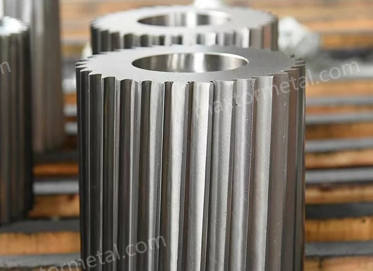
Rotor and knife materials
Knife metallurgy and documentation underpin both reliability and QA sign‑off. Typical, widely used options include:
- D2/SKD11 tool steel: commonly hardened to roughly HRC 58–62, balancing wear resistance and toughness for general PP/PE strand cutting. Reference material families are summarised by specialist knife suppliers and OEM context pages.
- M2 high‑speed steel: around HRC 55–62 with good hot‑hardness, suited to higher speed lines and keen edges.
- 440C stainless: roughly HRC 58–60 with improved corrosion resistance for wet environments.
- Tungsten‑carbide bed knives or inlays: effective hardness often equivalent to HRC 68–72 (or >1500 HV), valuable for glass‑filled or abrasive recyclate; many OEMs offer solid‑carbide bed knives in their brochures (see the note on solid carbide in the MAAG S3500 brochure).
For hardness verification, request Rockwell C test data compliant with ASTM E18 or ISO 6508‑1, including load, locations, and 3–5 readings with ranges, traced to the part ID and heat lot. Practical primers on Rockwell testing explain the diamond indenter and 150 kgf major load used for HRC (ASTM E18 overview; Buehler Rockwell guide).
Where a custom blade set is needed, suppliers such as MAXTOR METAL can manufacture to your drawings, sketches, or samples and provide material, heat‑treat, hardness, and dimensional tolerance reports. In procurement, specify steel grade, target hardness band, edge geometry, and tolerances (e.g., ±0.01–0.05 mm on thickness/hole patterns) and request traceable documentation. For examples of documentation scope and product fit, see the company’s neutral guidance and product pages: the Best‑practice guide for pelletising knives outlines documentation expectations, and the plastic pelletizer blade pages show mounting styles and options (MAXTOR METAL pelletising knives guide; MAXTOR METAL plastic pelletizer blade product). When issuing an RFQ/PO, include the material mill cert and heat/batch number, the heat‑treatment report with target hardness, an ASTM E18/ISO 6508‑1 hardness sheet with multiple readings and locations, a dimensional report (length/width/thickness, hole spacing, parallelism/runout) tied to part ID, and the specified edge geometry (hone radius/chamfer, carbide inlay notes) so QA can sign off without delay.
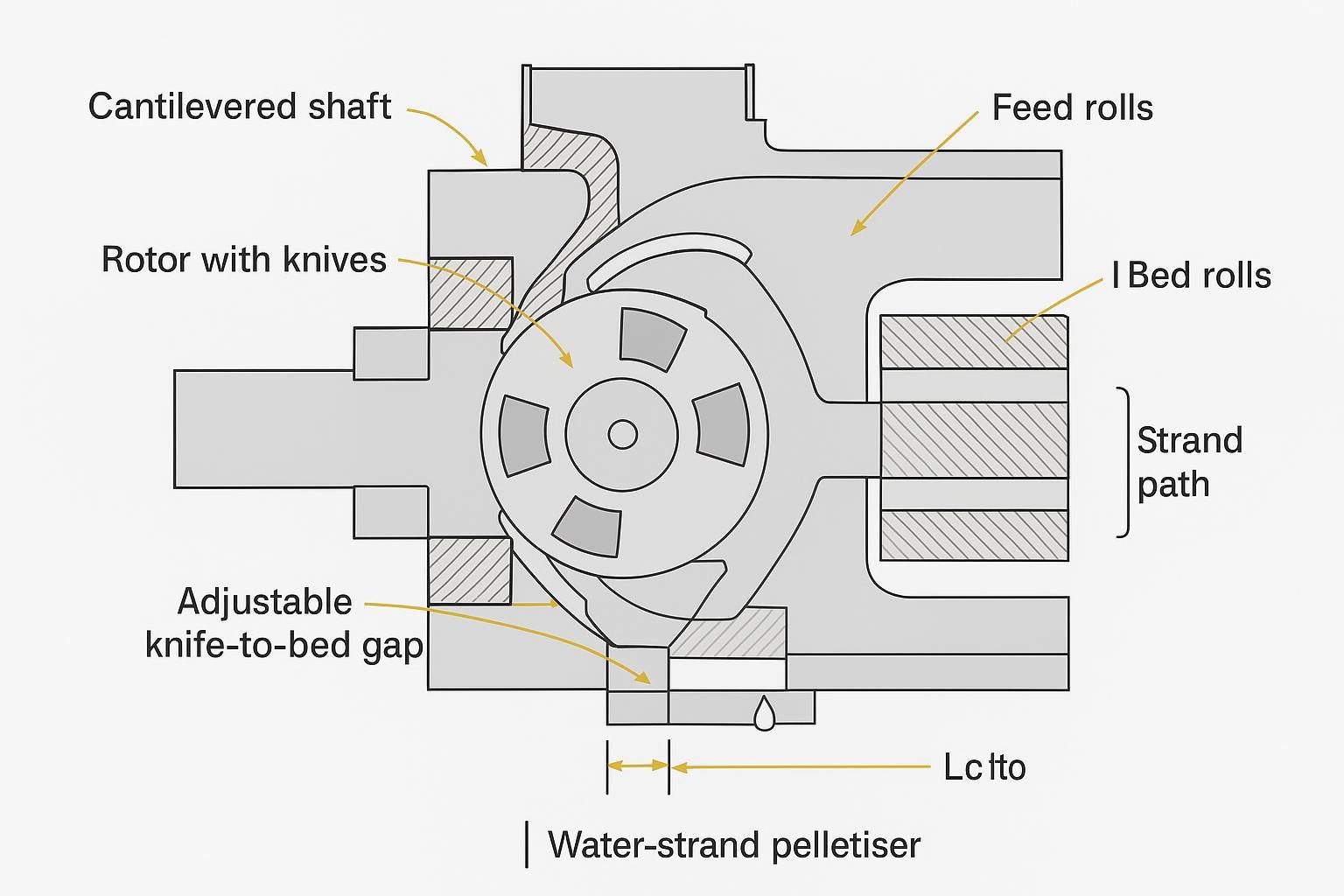
Gap control and cutter stiffness
OEM literature often shows micrometric adjusters (eccentrics, push–pull bolts) that allow extremely fine knife‑to‑bed gaps—down to a few hundredths of a millimetre in some models. Treat these as capability limits rather than fixed setpoints; a practical starting method is to bring the rotor edge to a uniform, light “kiss,” then back off to a running clearance aligned to polymer and pellet size. Engineering starting ranges for water‑strand lines are typically 0.05–0.10 mm for unfilled PP/PE and 0.10–0.20 mm for glass‑filled/abrasive mixes. Stability depends on stiffness and alignment: look for reinforced supports, precision bearings, and dowel‑pinned faces that repeat location after each swing‑open. For examples of quick‑access designs engineered to retain alignment, see MAAG’s slide/pivot chambers and BPM’s quick‑clean families (MAAG S3500 brochure; BPM Training PDF).
Wet‑end integration and dewatering
Strand moisture carry‑over drives fines and smear during restarts. Pair the cantilevered access with robust drying: non‑contact air knives or vacuum‑air‑knife (VAK) systems that separate droplets and keep the feed area dry help stabilise cut quality and colour. Bay Plastics Machinery’s training materials describe VAK strand dryers using a single blower with demisting and drainage—an approach that supports consistent restarts with minimal water ingress (BPM Training PDF). Select controlled drainage at the water slide and avoid pooling near the feed rolls.
Quy trình vận hành tiêu chuẩn (SOP) cho việc thiết lập và bảo trì
Knife‑to‑bed setting guidance
Safety first. Apply full lockout/tagout, isolate the drive, and drain the water box to a safe level before opening. Keep fingers clear of edges and moving parts; use cut‑resistant gloves and eye protection.
- Baseline set: With fresh or reground knives, jog the rotor to align a knife over the bed knife. Bring the edges to a light, even touch across the full width. Back off to the starting clearance appropriate to the run (see table below). Verify at the left/middle/right with feeler gauges.
- Verify by cut: Start slowly and inspect the first pellets under 10–20× magnification. Clean shearing without smear, low tails, and no bright burrs indicate a good set. If chatter appears, open by 0.02–0.03 mm or reduce feed for a minute to stabilise.
- Record settings: Log polymer, strand count/diameter, pellet length target, gap readings, amperage draw, fines %, tails %, and Lab* deltas so you can reproduce the setup for your cantilevered pelletizer rotor on the next similar job.
Gap starting points (engineering guidance; validate on site):
| Polymer/fill and pellet aim | Starting clearance (mm) | Ghi chú |
|---|---|---|
| Unfilled PP/PE, 2–3 mm pellets | 0.05–0.10 | Aim for crisp shear; increase if chatter |
| PET/PA unfilled | 0.07–0.12 | Ensure strands are well dried |
| 20–40% glass‑filled PP/PA | 0.10–0.20 | Prefer carbide bed knife; avoid chipping |
| High‑recycle with fines | 0.10–0.18 | Prioritise strand drying and frequent checks |
These values align with fine‑adjust capability mentioned in OEM literature but must be confirmed by your own QA.
For a practical, step‑by‑step blade replacement reference, see this neutral guide to safe, efficient blade changes on pelletisers, which covers tools, sequencing, and verification checks (replace pelletizer blades safely and efficiently).
Cleaning and colour‑change steps
Clean quickly and methodically to prevent carry‑over. Swing or slide the chamber open; vacuum loose pellets and dust, then wipe with lint‑free cloths. Use polymer‑safe solvent sparingly and avoid spraying near bearings and seals. If micro‑chipping or rounding is visible, replace or rotate to a fresh edge and re‑confirm the gap. Lower the water level to the minimum effective; ensure the air‑knife/VAK is operating correctly. Restart at reduced throughput, discard the first 1–3 minutes, then check Lab* colour deltas and sieve for fines before ramping up.
Bearings, seals, and corrosion care
A water‑strand environment adds moisture and washdown chemicals to the usual shock and vibration. Where possible, choose sealed, corrosion‑resistant bearing units with multi‑barrier seals and stainless flingers, similar in concept to hygienic “food‑line” units engineered for wet service; OEM application notes from bearing makers explain why such housings tolerate frequent washdowns and help keep grease where it belongs (SKF Food Line overview). If you run standard units, relubricate more frequently in splash zones (daily to weekly depending on speed/temperature) until a small purge appears at the seals, following manufacturer guidance. Keep water circuits clean, drain housings after washdown, avoid directing high‑pressure jets at seals, and schedule daily visual checks for leaks, unusual heat, or vibration. Small habits here pay back with longer bearing life and steadier gap control.
A cantilevered pelletizer rotor turns colour changes from a lengthy strip‑down into a controlled, quick sequence. The result is faster restarts, more stable pellets, and typically lower fines and tails—without increasing risk to operators or QA. As you consider upgrades, validate mechanical fit and stiffness on your line, request traceable material/heat‑treat/hardness/tolerance documents with any new knife set, and pilot the configuration on your most abrasive grades to lock in gap settings and purge times.
Pilot validation protocol (no site data required)
If you want to justify a cantilevered pelletizer rotor upgrade with evidence—without relying on OEM marketing—run a simple A/B changeover trial on your own line and archive the results.
- Scope: Same polymer family, same strand count/diameter, same pellet length target; compare your current cutter versus a cantilevered/swing‑open access design.
- Time stamps: Record (1) LOTO start, (2) chamber open, (3) knives set complete, (4) first pellets, (5) first “OK” pellets released.
- Quality metrics: fines %, tails %, pellet length consistency, and colour delta (e.g., Lab* / ΔE) at 1, 3, 5, 10 minutes after restart.
- Rác thải: Purge scrap (kg) and time-to-spec.
- Process conditions to log: water box level/flow/temp, dryer settings (air knife/VAK), feed-roll speed, rotor rpm, and knife-to-bed gap readings (L/M/R).
- Documentation pack: tie the trial to traceable knife paperwork (material cert, heat-treat report, hardness per ASTM E18/ISO 6508-1, and dimensional report) so QA can audit the result.
Safety and standards note
This guide provides engineering starting points and must be validated against your machine OEM manual and site EHS procedures. For hazardous energy control, refer to OSHA 29 CFR 1910.147 (The control of hazardous energy—lockout/tagout) and ISO 14118:2017 (Safety of machinery — Prevention of unexpected start-up).
Tommy Tang is a Senior Sales Engineer at Nanjing METAL Industrial với 12 years’ experience supporting industrial blade selection and procurement. Certifications: CSE, CME, Six Sigma Green Belt, PMP.