

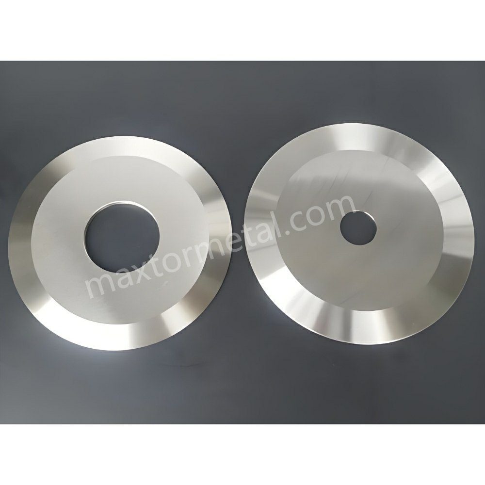
Змеевидный рез (также называемый уводом или дрейфом линии реза) происходит, когда отрезанная кромка не держит прямую и стабильную траекторию: полосы «гуляют», осциллируют или постепенно смещаются, из-за чего слои намотанного рулона теряют соосность. Относитесь к этому как к комплексной проблеме стабильности всей системы продольной резки и намотки, а не как к дефекту одного параметра.
Этот чек-лист отражает подход, который большинство сервисных и технологических служб использует для устранения неполадок на производстве. Он основан на диагностической последовательности, применяемой инженерами Maxtor Metal при выезде на объекты, когда рез, выглядящий идеально при настройке, теряет стабильность на рабочих скоростях.
Ключевой выводЕсли траектория движения меняется в зависимости от скорости, подготовки к повороту или положения на полосе, начните с изоляции противника. откуда исходит боковая сила (силы ножа против механики паутины против воздуха/статического напряжения) прежде чем вы начнете “крутить ручки”.”
Этот системный подход к диагностике является основой, которую инженерно-техническая служба Maxtor Metal использует при поддержке клиентов на линиях продольной резки пленок и нетканых материалов, где снос полосы не удавалось устранить точечными (однофакторными) настройками.
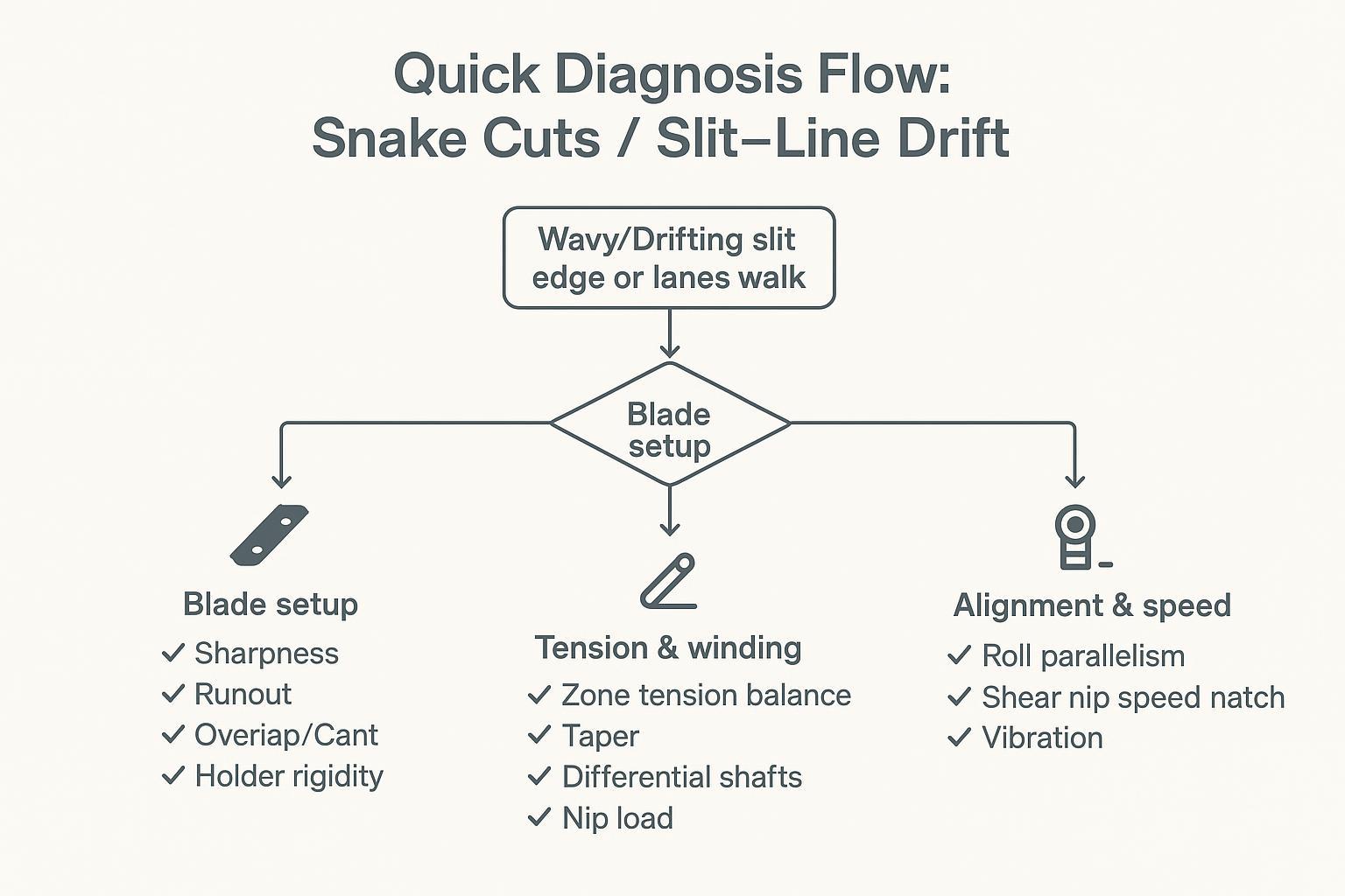
Быстрая схема диагностики
Когда следует подозревать проблемы с лезвием
- Проблема в том, что полоса движения (одна или две полосы смещаются в сторону, в то время как соседи сохраняют свои позиции).
- Начало дрифта прямо в точке разреза, даже на низкой скорости.
- Вы недавно меняли ножи, прокладки, держатели или перемещали стопку ножей.
- Смещение имеет повторяющийся характер “один раз за оборот” (часто связанный с биением или неровностью посадочного места).
Быстрые проверки:
- Проверьте чистоту стопки ножей (отсутствие прилипшей пленки, клея, заусенцев на поверхностях).
- Проверка биения циферблатного индикатора на поверхностях оправки/ножа на полосах движения, где происходит смещение.
- Убедитесь, что перекрытие/зацепление и угол наклона/траектория находятся в пределах ожидаемого диапазона для метода резки.
Когда следует подозревать натяжение/наматывание
- Дрейф усиливается по мере диаметры валков.
- Дефект “перемещается” с одной полосы движения на другую. ключевая позиция или изменения в конструкции башни.
- Понимаете телескопический, неплотные края или различия в твердости от полосы к полосе.
- Дрифт мгновенно улучшается, когда вы снизить скорость или изменить заданные значения натяжения.
Быстрые проверки:
- Сравните натяжение в зонах размотки/середины полотна/намотки (фактическое и заданное).
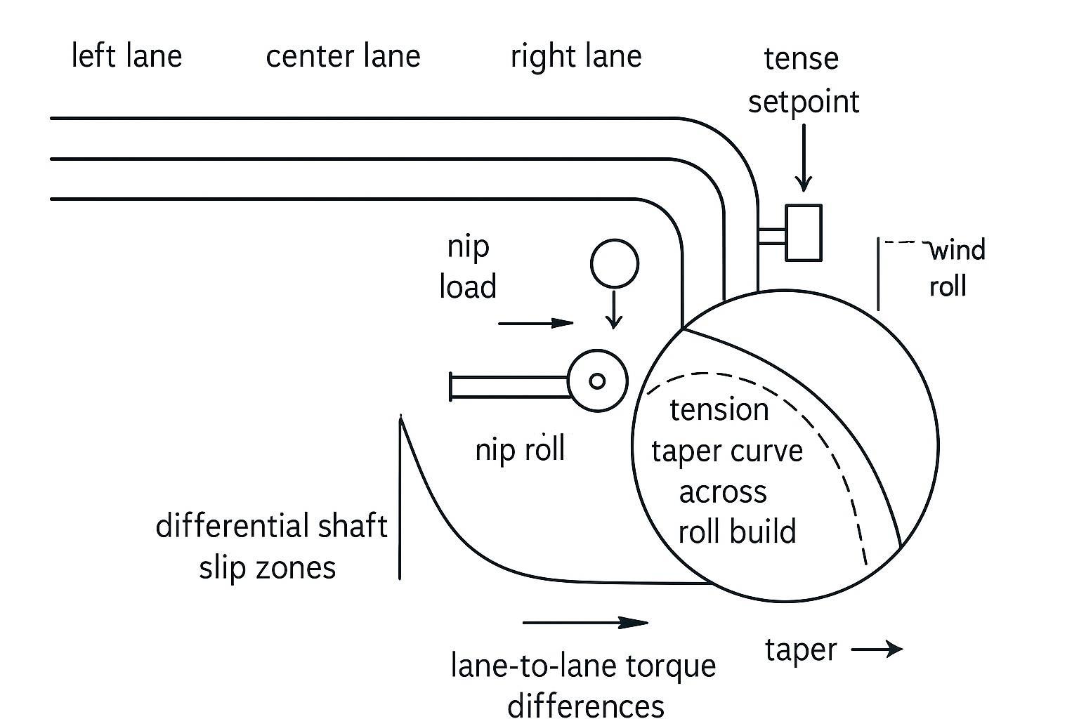
- Проверьте поведение натяжения конуса по всей длине валка.
- Убедитесь, что проскальзывание дифференциала работает по каждой полосе движения (нет заклинивших элементов).
Когда следует подозревать несоответствие/скорость
- Смещение усиливается после технического обслуживания, замены подшипников или удара/перегрузки.
- Паутина хорошо движется вверх по течению, а затем смещается после определенного поворота или зацепа.
- Вы слышите/чувствуете вибрацию, видите следы рисунка или наблюдаете колебания направляющей кромки.
Быстрые проверки:
- Проверяйте параллельность валиков и балансировку прижимных сил; обращайте внимание на явное перекос или неравномерный износ.
- Согласование скорости в зоне среза (скорость ножа относительно скорости полотна).
- Состояние подшипников и вибрация (температура, шум, спектр, если имеется).
Матрица первопричин змеиного разреза
Используйте эту таблицу в качестве справочника для быстрой оценки ситуации перед внесением каких-либо изменений в настройки.
| Характер симптомов | Наиболее вероятная подсистема | Первая проверка |
|---|---|---|
| Смещение в зависимости от полосы движения, начинается у края полосы, проявляется на низкой скорости. | Держатель лезвия | TIR на участках с древовидной структурой и режущими поверхностями на затронутых полосах; сравните со стабильными полосами. |
| Дрифт усиливается по мере нарастания крена; улучшается при снижении скорости. | Натяжение / дифференциальная намотка | Фактическое натяжение в каждой зоне по сравнению с заданным значением; дифференциальный момент проскальзывания вала. |
| Смещение появилось после технического обслуживания или поломки оборудования. | Выравнивание / подшипник | Параллельность качения; спектр температур и вибраций подшипника. |
| Смещение зависит от положения родительского участка или полосы движения (край или центр). | Материал / профиль толщины | Изменение толщины полотна поперек полосы; корреляция твердости от полосы к полосе с положением основного валка. |
| Снос ухудшается на высоких скоростях и улучшается при увеличении давления при сжатии. | Захват воздуха / статическое напряжение | Проверка снижения скорости; проверка выходной мощности ионизатора и целостности заземления. |
Настройка ножей и допуски
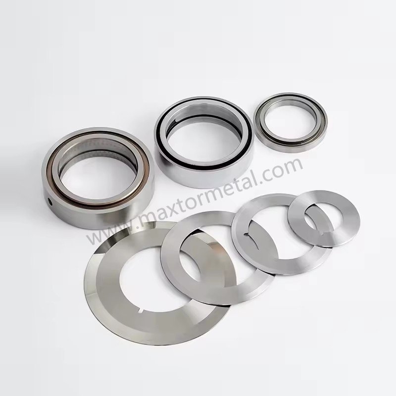
Резкость, вылет, наложение, наклон
Срезы типа “змея” часто начинаются с небольшого, повторяющегося бокового отклонения. Во многих линиях самый быстрый способ подтвердить или опровергнуть «смещение, вызванное ножом», — это измерить дистанцию в тех местах, где это имеет значение.
- РезкостьЗатупленный край увеличивает силу резания и может “направлять” полотно, особенно при работе с тонкими пленками на высоких скоростях.
- Выход за пределы допустимого диапазона (TIR)Проверяйте плечи вала, поверхности распорок и поверхности ножей — не только одну удобную точку. Поддерживайте общее индикаторное биение в пределах допустимых значений. ≤0,025–0,050 мм (0,001–0,002 дюйма) По всей сборке. В системе входного контроля Maxtor Metal регистрируется TIR как на поверхности ножа, так и на контактной поверхности вала для каждой партии, поэтому полевые измерения можно сравнивать с документированными заводскими данными, когда после замены ножа возникает проблема с отклонением. Для получения информации об осевом и радиальном TIR, включая протоколы проверки отклонения от холодного состояния к горячему и механизмы дефектов, возникающие при каждом режиме биения, см. Осьal Runout, Dynamic TIR, and Slit Edge Quality.
- Перекрытие / взаимодействиеУстановите значение перекрытия на минимальное стабильное значение для вашего метода и материала (обычно начиная с 0,5–1,2 мм / 0,020–0,045 дюйма (для стандартной резки пленок методом сдвига). Чрезмерное перекрытие может временно маскировать механическую проблему, одновременно увеличивая нагрев и боковую нагрузку. Для тонких пленок (ПЭ/ПП/ПЭТ <50 мкм) группа инженеров Maxtor Metal использует диапазон 0,50–0,75 мм в качестве начального значения и корректирует его в зависимости от качества кромки и тенденции изменения силы резания. Подробное описание взаимодействия перекрытия, угла наклона и пружинной предварительной нагрузки во время настройки см. в Пружинная конструкция для продольной резки с нулевым зазором: контроль перекрытия, угла наклона и предварительной нагрузки..
- Кант / трамвай: Углы наклона должны соответствовать спецификациям производителя (как правило). 0.25°–0.5°Если станок неправильно настроен, то при настройке качество резки может выглядеть приемлемым, но становиться нестабильным по мере увеличения усилия с ростом скорости.
В качестве справочного материала по резке ножницами полезно использовать руководство DIENES Slitting Reference Guide, в котором рассматривается перекрытие как контролируемая переменная, а не как параметр, где “чем больше, тем лучше” (см. Справочник по продольной резке DIENES, 2-е изд. (PDF)).
Для линий, где также рассматривается выбор покрытия — в частности, влияет ли покрытие DLC или PTFE на характер сноса и интервалы очистки — см. Выбор покрытия DLC или PTFE для продольно-резательных ножей: износ против налипания материала.
Жесткость держателя и боковая нагрузка
Даже с качественными ножами гибкий держатель или стопка, допускающая изменение боковой нагрузки, на высокой скорости может привести к смещению в сторону.
Чеки, которые обычно приносят результат:
- Убедитесь, что держатели установлены ровно и надежно зафиксированы по всей стопке.
- Проверьте наличие фрикционных повреждений, заеданий или следов износа, указывающих на микроскопические смещения под нагрузкой.
- Убедитесь, что проставки не приводят к “накоплению допусков” и не вызывают бокового смещения (особенно при многополосной сборке).
- Обратите внимание на увеличение боковой нагрузки, коррелирующее с образованием валков или повышением температуры.
Проблемы с комплектацией распорок часто связаны с точностью подгонки отверстий. Логику выбора посадки по стандарту ISO 286, определяющую точность позиционирования отверстия относительно вала, а также порядок проверки собранного TIR-комплекта перед поступлением ножевого блока в производство, см. в соответствующем разделе. Допуск на центральное отверстие и биение: оптимизация посадки по стандарту ISO 286 для высокоскоростных ножей для продольной резки..
Качество поставляемой продукции имеет гораздо большее значение для стабильности настройки, чем это учитывает большинство команд. Партии ножей с непостоянной твердостью или неравномерными размерами создают переменную, которая выглядит как проблема с настройкой, но не реагирует на корректировку настроек.
Документ Maxtor Metal содержит данные о твердости, размерах и отслеживаемости партий/отношений для всех поставок ножей для круговой резки — таким образом, если после замены ножа возникает проблема с отклонением параметров, расследование может начаться с проверенных данных по поступающей партии, а не с анализа симптомов в обратном порядке.
Для OEM/ODM-проектов, где ножи должны соответствовать устаревшим держателям, оправкам или инженерным чертежам, Maxtor Metal предоставляет полную поддержку в разработке индивидуальных спецификаций, чтобы избежать превращения простой замены ножа в цикл проб и ошибок по геометрии.
Для понимания математических расчетов, определяющих, как изменение толщины каждого ножа приводит к ошибке ширины щели в многополосной установке, а также для применения метода подбора прокладок с целью минимизации осевого смещения при переналадке, см. Контроль кумулятивного допуска толщины при многоножевой продольной резке.
Выбор между ножницами, бритвой и прессованием.
Подберите метод резки в соответствии с материалом и дефектом, с которым вы боретесь:
Перед выбором метода резки необходимо также учитывать соответствие геометрии фаски жесткости подложки — одинарная фаска, подходящая для тонкой полиэтиленовой пленки, будет вести себя иначе на ПЭТ-ламинатах. Подробную информацию о выборе метода резки, основанного на жесткости подложки и охватывающего одинарные, двойные и сложные профили фаски, см. в [ссылка на соответствующий раздел]. Одинарные, двойные и комбинированные фаски для ножей для круговых режущих кромок.
- Продольная резка: Лучше всего подходит, когда требуется стабильное качество кромки и сохранение геометрии (биение, перекрытие, боковая нагрузка). Как правило, стабилен при правильной механической настройке.
- Распиливание бритвойПростой и чистый способ резки тонких пленок, но чувствительный к состоянию лезвия, положению канавки и стабильности полотна. Положение канавки имеет значение: если канавка слишком мелкая относительно толщины полотна, лезвие отклоняется вбок под действием натяжения полотна, и траектория резки смещается при изменении скорости полотна; если слишком глубокая, полотно обхватывает края канавки, и отслеживание становится чувствительным к любой асимметрии бокового натяжения. Смещение также может быстро возникать, когда полотно движется по воздушной пленке на высокой скорости или когда статическое напряжение увеличивает боковое сцепление с направляющими поверхностями.
- Раздавливание и резкаВ некоторых конфигурациях может быть достаточно снисходительным, но также может усиливать рыскание при изменении состояния резины/наковальни или при нагреве.
| Категория субстрата/пленки | Рекомендуемый метод | Ключевое преимущество | Фактор риска дрейфа |
|---|---|---|---|
| Тонкий полиолефин (BOPP / PE) | Бритва в канавке / Срез | Чистый край прорези, минимальное количество пыли. | Отклонение лопастей, плавание в воздухе |
| Жесткие / Высокомодульные (ПЭТ, ПВХ) | Продольная резка | Точная геометрия среза, чистые кромки | Биение ножа, смещение при наклоне |
| Толстые/ламинированные пленки | Срез / Тяжелое дробление | Высокая способность выдерживать сдвиговые нагрузки | Изменение боковой нагрузки, износ лезвия |
Для описания структуры, основанной на методе планирования экспериментов (DOE) и отображающей взаимодействие глубины перекрытия и бокового зазора в различных категориях подложек, включая модель компромисса Парето между качеством кромки и сроком службы ножа, см. Оптимизация глубины перекрытия круглого ножа и бокового зазора..
Если вы наблюдаете змеевидную резку только на определенных артикулах, пересмотрите, соответствует ли метод толщине пленки, модулю упругости, коэффициенту трения и диапазону скоростей.
Контроль натяжения и намотки
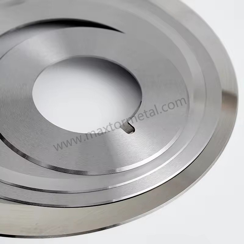
Уставки и профили
Натяжение — это не просто число, это профиль по зонам и во времени. Стабильность траектории щели зависит от стабильного состояния деформации полотна.
Практические правила, которые доказали свою эффективность:
- Поддерживайте стабильное натяжение по всей длине. размотать → диапазон процесса → перемотать, и сверить фактические измерения тензодатчиков с заданными значениями контроллера. Сдвиги натяжения, превышающие ±5%–8% Отклонение от цели часто бывает достаточным для того, чтобы вызвать боковое проскальзывание стенки и инициировать дрейф щелевой линии. Полевая группа Maxtor Metal использует этот диапазон ±5%–8% в качестве порогового значения при анализе данных о натяжении во время исследований после дрейфа на линиях потребителей.
- Натяжение при конусном изгибе следует использовать целенаправленно; по мере увеличения диаметра натяжение часто необходимо уменьшать, чтобы избежать телескопического выдвижения, деформации кромок или повреждения сердечников.
В качестве отправной точки для разработки рекомендаций по натяжению полотна, основанных на стандартах, TAPPI публикует документы с рекомендациями по натяжению, такие как: TAPPI TIP 0200-01:2021 (рекомендации по натяжению полотна).
Дифференциальные валы и зазоры
Разница в скорости намотки часто определяет разницу между “последовательными полосами движения” и “полосами, по которым можно свободно двигаться”. Когда диаметр полос увеличивается с немного разной скоростью, системе необходим контролируемый способ выравнивания крутящего момента, чтобы одна из полос не ослабла и не начала отклоняться от курса.
Проверки:
- Убедитесь, что элементы дифференциала действительно проскальзывают в пределах ожидаемого диапазона крутящего момента.
- Убедитесь, что нагрузка в зоне контакта равномерно распределена по всей поверхности валка; неравномерность зоны контакта может привести к различиям в сцеплении между полосами движения.
- Проверьте натяжение конуса вместе с настройками дифференциала; если вы будете затягивать натяжение по мере увеличения диаметра, вы можете перегрузить одну из полос и нарушить устойчивость движения.
Переходы и тяга
Многие стрижки “под змею” являются «дефектами перехода»:
- ускорение до скорости производства
- соединительный проход
- передача башни
- Изменение твердости валков происходит по мере увеличения диаметра.
В переходные периоды:
- Убедитесь в стабильном сцеплении полотна с поверхностью (отсутствие резкого проскальзывания на определенном участке).
- Для диагностики кратковременно снизьте скорость. Если занос сразу же прекращается, следует заподозрить проблемы с тягой/динамикой подвески/статическим сопротивлением, прежде чем менять ножи.
- Рассматривайте «промах» направляющей лезвия как симптом, часто вызванный колебаниями натяжения, смещением или нестабильным сцеплением.
Соосность и синхронизация скорости
Валы, валы и балансировочная муфта.
Если из-за геометрических особенностей ткань деформируется вбок, ни одна настройка ножа не сможет постоянно удерживать её в прямом положении.
- Проверьте параллельность валков относительно осевой линии станка.
- Осмотрите поверхности валков на предмет конусности, износа, загрязнения или повреждений.
- Проверьте распределение давления в зазоре; неравномерное распределение давления в зазоре может направлять движение полотна.
Практическим справочником по основам отслеживания осевой линии и причинам бокового смещения является сборник Уокера, распространенный в сообществе специалистов по обработке веб-страниц (см. Web Lines: Walker on Web Handling (сборник 2003–2014 гг., PDF)).
Разница скоростей в зоне сдвига
При продольной резке несоответствие скоростей может создавать боковую составляющую силы в месте разреза.
Контрольный список:
- Убедитесь, что скорость вращения ножа соответствует скорости движения полотна в тех местах, где это требуется вашим методом резки.
- Убедитесь, что люфт в муфте привода не вызывает периодических колебаний скорости.
- Если смещение зависит от скорости, но не от натяжения, следует заподозрить несоответствие скорости и вибрацию.
Состояние подшипников и вибрация
Проблемы с подшипниками и вибрацией постоянно маскируются под “проблемы с прорезями”.
- Сравните температуру подшипников слева и справа.
- Прислушайтесь к циклическим шумам; проверьте наличие характерных признаков.
- Если у вас есть система мониторинга вибрации, запишите спектры на резцовой головке и перемотайте пленку.
Влияние материала и воздуха
Профиль и изменчивость измерительного прибора
Различия в толщине перемычки и изгиб создают неравномерную нагрузку на полосы движения. Перемычка, как правило, будет смещаться в сторону большей плотности.
Проверки:
- Проверьте соответствие профиля и твердости поступающего валка.
- Обратите внимание на различия между полосами движения, которые коррелируют с положением родительского элемента (край или центр).
- Если дрейф наблюдается только на определенных партиях, зафиксируйте идентификатор партии и данные профиля измерительного прибора в журнале.
Захват воздуха и укладка
Воздух на высоких скоростях является настоящим “механическим элементом”. Если полотно скользит по воздушной пленке, сцепление меняется, и разрез может сместиться.
Проверки:
- Обратите внимание на дрожание и плохое наложение линий при перемотке.
- Эффективно используйте метод прижима/защемления (в пределах возможностей оборудования), чтобы уменьшить количество захваченного воздуха.
- В качестве диагностического метода немного снизьте скорость и посмотрите, уменьшится ли дрейф.
Взаимосвязь статических и краевых дефектов
Статический заряд может притягивать пленку к направляющим/роликам, притягивать пыль и делать точки разделения нестабильными, особенно в случае тонких пленок при высоких скоростях.
Проверки:
- Проверьте целостность заземления/соединения в местах установки ключей.
- Проверьте ионизирующие пластины на чистоту и мощность излучения.
- Проследите, усугубляется ли дефект в условиях низкой влажности.
When static-attracted dust is itself a product quality problem—not just a trigger for tracking instability—the blade-level root causes of dust generation (Ra, carbide microstructure, overlap-induced secondary rubbing) require a separate analysis. See Root-Cause Analysis of Slitting Dust Generation: Blade Flank Ra, Carbide Microstructure & Setup Tolerances.
FAQs:
В: Что вызывает змеевидный рез при продольной резке пленок?
О: Змеевидный рез обычно вызван поперечной нестабильностью: усилиями на ноже (биение, перекрытие, люфт держателя), механикой полотна (дисбаланс натяжения, проблемы дифференциальной намотки), геометрией (несоосность, неравномерный прижим) или динамикой (захват воздуха и статика). Самый быстрый способ диагностики — определить, начинается ли увод полосы на ноже или проявляется непосредственно при намотке.
В: Как определить, вызван ли увод линии реза проблемой с ножами или с натяжением?
О: Если проблема возникает на конкретной полосе и начинается непосредственно в узле резки даже на низкой скорости, скорее всего, дело в ножах, биении (runout) или держателях. Если увод усиливается по мере намотки рулона, уменьшается при изменении натяжения или смещается вместе с гильзой, причина кроется в натяжении или дифференциальной намотке.
В: Может ли биение ножа (runout) действительно вызывать увод полосы при продольной резке?
О: Да. Даже небольшое торцевое или радиальное биение может создавать циклическую поперечную силу, смещающую траекторию реза. Измерьте биение на валу (арборе), торцах дистанционных колец (проставок) и плоскостях ножа с помощью индикатора часового типа, а затем сравните параметры на «хороших» и «проблемных» полосах.
В: Какие настройки натяжения помогают остановить увод линии реза на бобинорезательной машине?
О: Начните со стабилизации натяжения в каждой зоне и проверки фактического натяжения с помощью измерений. Затем используйте контролируемый профиль конусного (убывающего) натяжения (taper profile), чтобы натяжение не возрастало по мере роста диаметра рулона. Рекомендации TAPPI помогут выбрать начальный диапазон, после чего настройте параметры на основе твердости намотки рулона и стабильности полос.
В: Предотвращают ли фрикционные (дифференциальные) валы увод полосы и телескопический сдвиг рулона?
О: Они помогают при неравномерном увеличении диаметра отдельных полос, так как контролируемое проскальзывание выравнивает крутящий момент, не позволяя отдельным полосам провисать и смещаться. Однако если фрикционные элементы заклинивают или крутящий момент настроен неправильно, все равно могут возникать разница в плотности намотки между полосами и их увод.
В: Почему увод линии реза усиливается при увеличении скорости?
О: Высокая скорость увеличивает воздушный захват, усиливает вибрацию и делает даже незначительные перекосы критическими. Если при снижении скорости увод полосы быстро уменьшается, причиной скорее всего являются аэродинамический фактор, сцепление (тракция) или статика, а не геометрия ножей.
В: Как уменьшить захват воздуха при намотке пленки?
О: Повысьте эффективность прижимного (прикатывающего) вала (lay-on/nip roller) в пределах допустимых параметров оборудования, проверьте геометрию проводки полосы на участке намотки и настройте натяжение/конусность (taper), чтобы полотно прилегало к рулону, а не «скользило» по воздушной подушке. Быстрый тест со снижением скорости позволяет точно подтвердить, является ли воздух причиной нестабильности.
В: Где следует фиксировать данные, чтобы предотвратить повторное появление волнообразного реза (snake cuts)?
О: Ведите учет по ID рулона и полосе: сборка ножевого блока (внешний диаметр, толщина, проставки), показатели биения (runout), настройки перекрытия (overlap) и угла наклона (cant angle), натяжение по зонам и профиль конусности (taper), тип и параметры вала намотки, скорость, статус контроля влажности и статического электричества, а также изменялся ли увод с ростом скорости или диаметра рулона.
Заключение
Устранение змеевидного реза (snake cuts) требует отказа от хаотичной подстройки параметров наугад и перехода к системной физически обоснованной процедуре диагностики. Путем последовательной проверки геометрии ножа и жесткости держателя (с поддержанием TIR ≤ 0,050 мм и надлежащих настроек перекрытия и угла наклона), стабилизации профилей натяжения полотна в зонах намотки, а также устранения несоосности валов оборудования и аэродинамического захвата воздуха на высоких скоростях, линии конвертинга полотна способны обеспечить мгновенную стабильность линии реза.
Чтобы превратить этот контрольный список в долгосрочные операционные преимущества, предприятиям следует формализовать данные проверки в стандартную операционную процедуру (SOP). Внедрение стандартизированного листа наладки с обязательным утверждением показателей биения (runout), перекрытия (overlap) и натяжения, а также ввод строгого графика профилактического обслуживания (PM) для ножедержателей, валов и подшипников позволяют кардинально снизить вариативность при переналадке оборудования.
Для предприятий, стандартизирующих оснастку на нескольких линиях продольной резки, Maxtor Metal поставляет дисковые сдвиговые ножи с предоставлением полной документации по Размерам и твердости для каждой партии, а также обеспечивает поддержку OEM/ODM при необходимости соответствия ножей существующим чертежам валов и держателей. Круглые ножи и лезвия от Maxtor Metal для справки по геометрии и техническим характеристикам.
В конечном итоге, оценка эффективности этих мер контроля стабильности сводится к ключевым показателям производительности. Высокоэффективные предприятия по переработке отслеживают пять основных KPI для подтверждения качества резки:
- Тариф на металлолом и отходы (%): Прямое сокращение отходов обрезанной пленки и бракованных рулонов, не соответствующих техническим требованиям.
- Общая эффективность оборудования (OEE)Более высокая скорость работы и стабильная устойчивость реза.
- Незапланированный простой: Меньше остановок линии, вызванных обрывами полотна или корректировками в процессе работы.
- Срок службы лезвияПовышенная износостойкость инструмента достигается за счет минимизации боковой нагрузки и оптимального перекрытия.
- Жалобы клиентов на качество продукции: Более низкая частота дефектов, связанных с переплетением кромок, телескопическим смещением или разрезанием, в готовых рулонных партиях.
Автор / Технический рецензент
Джерри Чу | Специалист технической поддержки (послепродажное обслуживание)
Maxtor Metal
Джерри обладает более чем 10-летним опытом работы в различных отраслях, включая производство бумаги, переработку и измельчение пластика, резку металла и обработку древесины. Специализируясь на решении реальных проблем, связанных с резкой, таких как заусенцы, чрезмерное пылеобразование и нестабильность кромок, он напрямую сотрудничает с инженерными группами на местах для оптимизации производительности инструмента и повышения надежности работы.
- СертификатыСертифицированный специалист по техническому обслуживанию и надежности (CMRP), сертифицированный специалист по управлению проектами (PMP®).
- Специализации: Устранение неполадок при резке на месте, разработка нестандартной геометрии лезвий и разработка стандартных операционных процедур для профилактического обслуживания.

 English
  Spanish
  Italian
  French
  Portuguese
  Russian
  German
  Arabic
  Hindi
Hindi  Vietnamese
  Indonesian
  Japanese
  Korean