

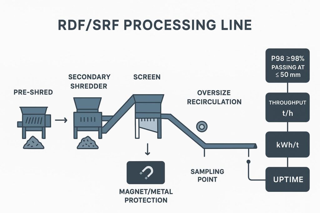
Los rechazos por tiras largas son un impuesto oculto en la producción de CDR/PDR. No solo no cumplen con las especificaciones del tamiz: también aumentan la carga de recirculación, incrementan el riesgo de enredo y elevan silenciosamente los kWh/t mientras reducen el rendimiento. Este artículo detalla las medidas de ingeniería para eliminar las tiras largas y alcanzar de manera constante un tamaño ≤50 mm con un cumplimiento del ≥98 % (P98) en líneas de clasificación limitadas por criba.
Resumen rápido:
- Objetivo: Eliminar los rechazos por tiras largas para alcanzar un tamaño ≤50 mm con un cumplimiento del ≥98 % (P98).
- Alcance: Trituración secundaria, clasificación limitada por criba, eficiencia en el procesamiento de CDR/PDR.
- Contexto normativo: EN ISO 21640; aceptación y reporte basados en tamizado.
- Palancas principales: Geometría de cortadores, estator de peine, cribas/OAR, luz de corte, control de alimentación y control de calidad.
Conclusión clave: Treat long strips as a problema del sistema (geometry + screen capacity + gap control + feed stability). Fixing only one lever rarely holds P98 in real mixed-waste variability.
Causas raíz
Flexible films and textiles
Flexible polymers and fibrous fractions (films, big-bag scraps, textiles, straps) tend to elongate, fold, and “draw through” the cutting zone. Instead of breaking into short particles, they can slip, ride the rotor, and emerge as long ribbons.
In low-speed shear size reduction, the goal is to keep the material in a repeated shear/re-engagement loop until it passes the sizing constraint. When flexible material avoids that loop—by stretching or wrapping—you get long strips and unstable particle length distribution.
Practical signals that film/textile behavior is dominating:
- Long strips spike during wet loads, low bulk density loads, or when film fraction increases.
- Power (kW) increases without a proportional throughput increase.
- Screen blinding or rotor wrap events correlate with strip length drift.
A quick field test before changing hardware: pull a typical “strip” by hand. If it stretches significantly before tearing, you need more positive capture and re-engagement at the cutter-stator interface.
Screen carryover and open area
In a screen-limited secondary shredder, the screen is more than a sizing device—it defines how many opportunities a particle gets to be re-cut before discharge.
Two screening fundamentals matter for strip control:
- Aperture (hole size) sets the target top-size.
- Open area ratio (OAR) sets capacity to pass—how much of the screen is actually open for material passage.
When OAR is too low (or becomes effectively low due to blinding, wear lips, or poor cleaning), flexible pieces can “surf” the screen, circulate longer, and either (a) finally pass as long strips, or (b) wrap and cause downtime. Screening theory recognizes open area as a key factor for capacity: higher open area increases available passage area and capacity, while reduced open area can increase retention and lower efficiency.
Shear gap and re-engagement
“Long strips” are often a symptom of insufficient re-engagement frequency.
Si el shear gap (rotor-to-stator or knife-to-counterknife clearance) is too large, a strip can bend and slide instead of being pinched and sheared. If the gap is uneven across the rotor width, you also get selective long-strip formation—operators will report “it’s always worse on one side.”
Film and textiles amplify this sensitivity because they deform rather than fracture.
En resumen: long strips form when flexible material stretches through an oversized or uneven shear gap and gets extra passing chances from low effective screen open area—geometry, gap, and screening act as one system, not three separate problems.
Diseño de cortadores y estatores

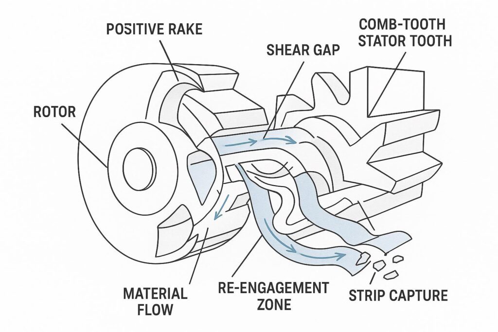
Positive-rake concave cutters
Geometry can be engineered to pull strips back into the cut instead of letting them ride through.
A positive-rake, concave cutter profile does two useful things in strip-prone feeds:
- Capture: the concave pocket and rake angle help grab thin, flexible material rather than letting it smear.
- Re-engage: when a strip tries to escape, geometry that promotes “hook-and-return” increases the chance it meets the stator again under load.
The goal isn’t aggression for its own sake—it’s stable, repeatable engagement that shortens length without creating excessive fines.
Comb-tooth stator beds
Comb-tooth stators act like a controlled “anti-strip fixture.” Instead of a single flat anvil edge, comb teeth create multiple localized engagement points.
Benefits for strip control:
- More bite points → more chances to catch long, flexible pieces.
- Shorter unsupported spans → less ability for strips to bow away.
- More consistent presentation → less sensitivity to small changes in feed density.
In strip-heavy RDF/SRF, a comb stator is often the difference between “mostly OK” and “stable P98.”
Edge prep and metallurgy
Edge sharpness matters—but in mixed waste it’s not just initial sharpness, it’s how the edge fails.
Two failure modes matter for strip control:
- Rounding (plastic deformation / wear): edges stop biting film and start pulling it.
- Micro-chipping: edges develop discontinuities that increase wrap initiation and heat.
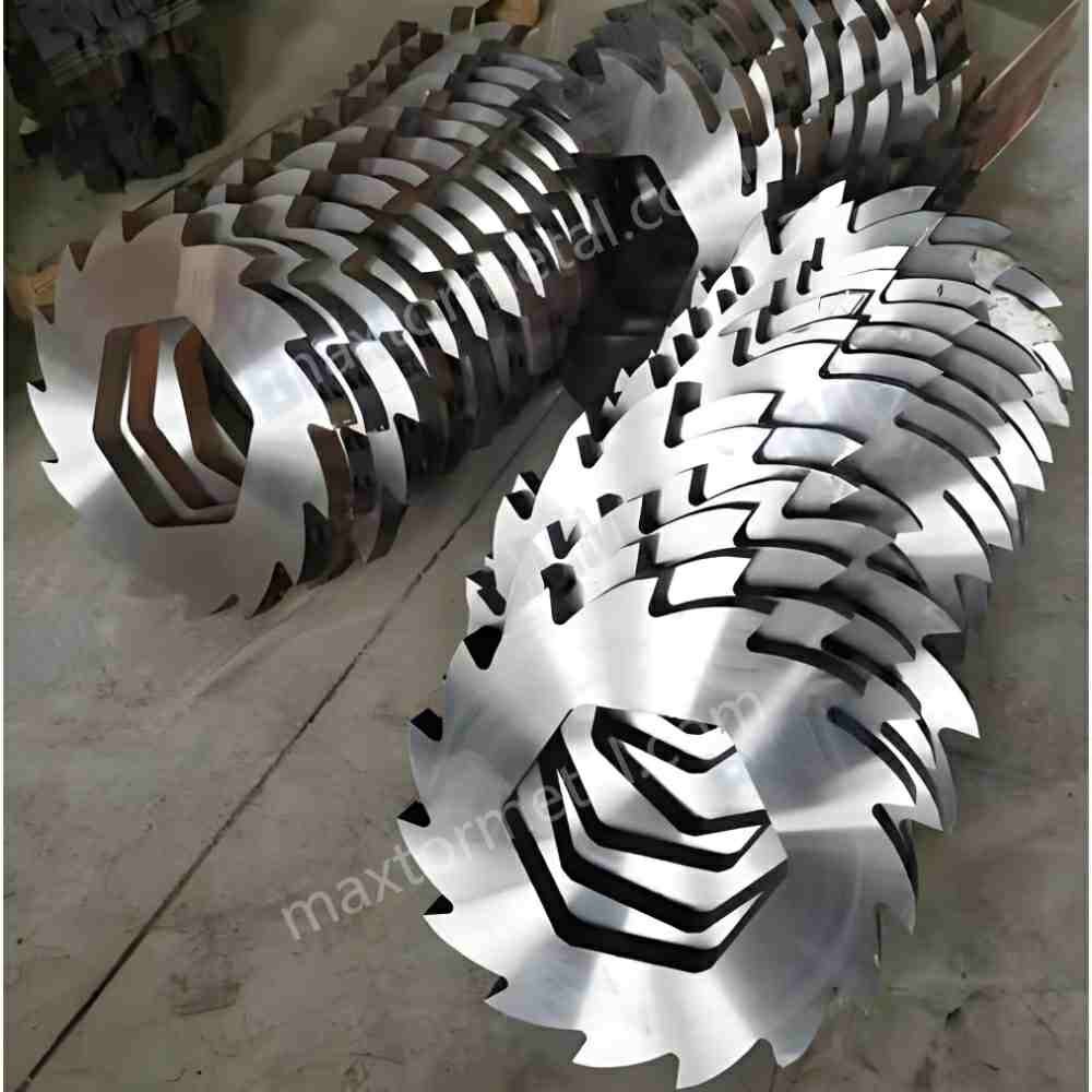
A practical QC approach—consistent with how Maxtor Metal positions its manufacturing discipline—is to treat shredder knives like a controlled wear component:
- verify incoming steel chemistry and traceability (heat/lot control),
- control heat treatment and hardness consistency batch-to-batch,
- confirm grind geometry and edge preparation against drawing tolerances,
- and validate fit-up so aftermarket knives don’t create clearance drift.
For the incoming-inspection workflow behind that verification—spec control, CMM sampling plans, and MTR documentation—see Adquisición de cuchillas para trituradoras postventa: Control de especificaciones, plan CMM, validación MTR y verificación de ajuste funcional..
That “OEM-fit” emphasis is not marketing fluff—it’s an engineering requirement. If the knife set cannot repeatably hold designed clearances and seating, you can’t hold particle size distribution.
For reference when specifying or qualifying replacement knives, the Maxtor Metal product page for Maxtor Metal shredder blades is a convenient place to align terminology and typical supply scope without turning the process discussion into a sales pitch.
En resumen: positive-rake concave cutters and comb-tooth stators work together to capture and re-engage flexible material, but the gains only hold if edge metallurgy and knife fit are controlled to spec.
Cribas y luces de corte
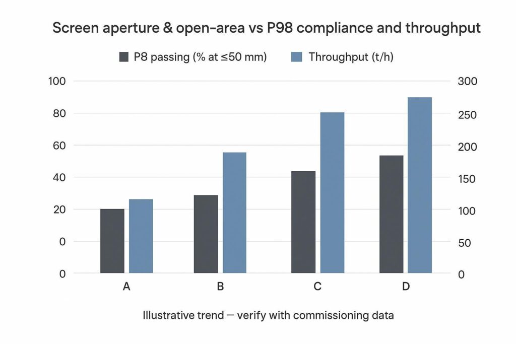
Aperture and open-area
For a spec like ≤50 mm at ≥98% passing, you’re optimizing the coarse tail—not the average size.
- Smaller apertures usually tighten the coarse end (better P98) but increase recirculation and energy.
- Higher OAR improves discharge capacity but can reduce “re-cut opportunities” if the system lets marginally-long pieces orient and slip through.
Screening references commonly define open area as the ratio of net aperture area to total screen area; higher open area increases available passage and capacity, while reduced open area can promote retention and blinding.
The right way to choose is to treat aperture and OAR as a pair and validate against both compliance and throughput.
A practical commissioning pattern:
- Start with the aperture that makes the spec achievable with margin.
- Then tune OAR (screen thickness, hole pattern, anti-blinding features, cleaning) to recover throughput without sacrificing P98.
If you need a standards-aligned way to define and report “oversize” and “long particles,” SRF particle-size determination methods like EN 15415-2 (maximum projected length method for large dimension particles) provide a defensible measurement framework you can cite in acceptance documentation.
Shear-gap tolerances
Gap control is the unglamorous lever that holds everything together.
Recommendations that usually survive real-world RDF/SRF variability:
- Set a target gap y una maximum allowable spread across the rotor width.
- Track gap drift as a maintenance KPI alongside kWh/t.
- When changing knife sets, treat clearance verification as a sign-off step, not an operator “feel” task.
For typical secondary shredder classes (e.g., 1.5 m to 2.8 m rotor width processing mixed RDF/SRF), target shear gap tolerances should be held between 0.5 mm and 1.2 mm depending on the rotor-to-stator setup. Furthermore, when reporting particle size distribution against EN 15415-2 or EN ISO 21640 standards, sampling mass and increment controls must account for measurement uncertainty (typically ±1.5% to ±2.0% P98 variance) caused by moisture variations and local film concentration.
Even small clearance changes can move you from “short chips” to “long ribbons” on film-heavy loads. The tolerance chain that keeps this gap stable across a multi-shaft rotor—GD&T callouts, spacer selective fit, and post-assembly TIR verification—is covered in Corregir el desgaste irregular: Guía de acumulación de tolerancias en cuchillas multieje.
Anti-wrap and deflectors
Anti-wrap isn’t only about avoiding downtime; it’s about keeping the material in the intended cut path.
Effective measures include:
- rotor-end and shaft deflectors that prevent film migration into dead zones,
- scrapers that keep the screen and stator interface clean,
- and maintaining edge condition so film is sheared rather than pulled.
When wrap events are frequent, treat them as a process symptom: it often means the system is spending too long in recirculation because P98 is not being achieved efficiently.
En resumen: choose aperture for the P98 target first, then tune open-area ratio and gap uniformity to recover throughput without giving up compliance.
Control de alimentación y riesgos

Residence-time stability
Residence time is the bridge between particle size and energy.
If feed swings, you can temporarily “pass” P98 by starving the chamber—but you’ll pay for it in throughput instability. Conversely, if you overload, you’ll see more smearing and strip formation.
Aim for:
- stable ram pressure / feed conveyor load,
- stable amperage profile,
- and stable recirculation return rate (oversize loop).
Tramp metal and moisture
Tramp metal triggers both performance loss and risk:
- It damages edges (accelerating strip formation).
- It forces operators to open gaps to avoid catastrophic contact.
Moisture changes friction and material handling:
- wet film and textiles are more likely to mat and wrap,
- and wet fines can blind screens, effectively reducing open area.
Upstream protection (magnets/metal detection) and moisture-aware operating windows are often the cheapest “strip control” you can buy.
Thermal growth allowances
Thermal growth shows up as clearance drift.
Even if your cold setup is perfect, sustained high-load operation can change rotor/stator relationships. If the machine design has limited thermal compensation, you may need:
- defined warm-up checks,
- thermal-state-specific gap targets,
- and stricter sign-off after long runs on high-friction feeds.
En resumen: residence-time swings, tramp metal, moisture, and thermal growth all show up as the same symptom—clearance and engagement drift—so feed stability protects the gap settings you already tuned.
KPI, puesta en marcha y ROI
Sieve plans and wording
If you want acceptance that doesn’t devolve into arguments, write your test plan like a contract.
Use clear definitions and methods:
- Reference ISO 21640 for SRF specification/class framing via the ISO catalog listing for ISO 21640:2021, Solid recovered fuels — Specifications and classes.
- Define particle size reporting using a sieve method standard like ISO 2591-1:1988 (Test sieving — General principles).
- For long/oversize particles, cite a method aligned to SRF practice such as the public catalog entry for “EN 15415-2:2012 (Maximum projected length method)”.
Then specify:
- sieve stack (aperture sizes),
- sample basis (as received vs dry),
- how many increments and total mass,
- P98 calculation method,
- and pass/fail wording (including what happens on a retest).
Throughput, kWh/t, uptime
For line economics, track three KPIs together:
- Throughput (t/h): the obvious one.
- Specific energy (kWh/t): the hidden cost of over-recirculation.
- Uptime (%): wrap events and screen blinding will dominate this.
A common failure is optimizing only one metric (e.g., smallest aperture to “make spec”) and losing overall efficiency. P98 is the constraint; throughput and kWh/t are the optimization variables.
Tuning matrix and payback
Commissioning should be treated like controlled experimentation.
Build a tuning matrix with rows like:
- cutter geometry (baseline vs positive-rake concave),
- stator type (flat vs comb),
- screen aperture,
- screen OAR/condition,
- shear gap setpoint,
- feed setpoint (ram pressure/conveyor speed),
- moisture band.
Salidas:
- P98 compliance,
- throughput,
- kWh/t,
- wrap events per shift,
- knife life (hours or tons between regrinds).
Payback usually comes from a combination of:
- fewer wrap stoppages,
- lower kWh/t at the same spec,
- and longer stable intervals between gap resets/knife interventions.
Field Case Study: 15 t/h Secondary Shredding Line Optimization
Case data below is drawn from an anonymized field commissioning engagement; customer identity and site details are withheld, and results reflect this specific line configuration rather than a guaranteed outcome.
To evaluate the combined impact of cutter geometry, comb stators, and shear gap management, a performance audit was conducted on a 15 t/h commercial RDF/SRF secondary shredding line handling high-film municipal solid waste fractions.
| Parameter / Metric | Baseline Setup (Flat Stator, Conventional Blades) | Optimized Setup (Positive-Rake, Comb Stator, 0.8mm Gap) | Performance Delta |
|---|---|---|---|
| P98 Passing (≤50 mm) | 89.0% (Non-compliant) | 98.5% (Compliant) | +9.5 percentage points |
| Specific Energy (kWh/t) | 21.5 kWh/t | 18.5 kWh/t | -14.0% energy reduction |
| Throughput Stability | 12.2 t/h average | 15.1 t/h average | +23.8% effective capacity |
| Rotor Wrap Events | 3.0 stops per 8-hr shift | 0.2 stops per 8-hr shift | 93.3% reduction in wrap downtime |
By stabilizing particle re-engagement and preventing film slippage, the line eliminated over-recirculation, allowing higher throughput at a significantly lower specific energy footprint.
The optimized configuration in this engagement used Maxtor Metal comb-tooth stator blades and positive-rake cutters specified to the OEM clearance drawing—consistent with the fit-and-traceability discipline described above.
When knife fit and repeatability are part of the constraint, linking your knife specification/qualification documentation to the relevant part families helps keep procurement and maintenance aligned without turning the engineering plan into a vendor selection exercise.
En resumen: track P98, throughput, and kWh/t together, not one at a time—the case data above shows how a coordinated tuning matrix converts compliance gains into real energy and uptime savings.
FAQs:
P: ¿Por qué mi trituradora produce tiras largas en lugar de partículas cortas?
R: Las tiras largas generalmente indican que el material flexible se está estirando o deslizando a través de la zona de corte en lugar de ser enganchado y cortado repetidamente. Las causas más comunes son bordes mellados o desgastados, una luz de corte (shear gap) excesiva o desigual, y una condición de criba/OAR que permite que las piezas "marginales" se orienten y atraviesen los orificios.
P: ¿Qué significa "P98 ≤50 mm" en el dimensionamiento de CDR/PDR?
R: Significa que el 98 % de la masa de la muestra pasa el criterio de 50 mm (dejando solo un 2 % de sobretamaño en masa). Se centra en el extremo grueso de la distribución granulométrica, que es precisamente donde aparecen las tiras largas.
P: ¿Cómo elijo la abertura de la criba para lograr ≤50 mm con un cumplimiento del ≥98 % (P98)?
R: Comience con una abertura que pueda alcanzar el objetivo P98 con un margen de seguridad bajo las peores condiciones de alimentación (alta proporción de film/textil). Luego, recupere el rendimiento mejorando el área abierta, el sistema antiobstrucción (anti-blinding) y la estabilidad de la alimentación, en lugar de agrandar de inmediato la abertura.
P: ¿Qué es la "relación de área abierta" (Open Area Ratio) de una criba y por qué afecta al rendimiento?
R: El área abierta es la proporción de la superficie de la criba que corresponde efectivamente a orificios libres. Un área abierta más alta generalmente aumenta la superficie disponible para el paso de partículas y mejora la capacidad de procesamiento; una menor área abierta efectiva (debido al diseño o a la obstrucción/blinding) reduces la capacidad e incrementa la retención y la carga de recirculación.
P: ¿Qué tan ajustada debe ser la tolerancia de la luz de corte (shear gap) para reducir las tiras largas?
R: Debe ser lo suficientemente ajustada para que el material flexible sea sujetado y cortado de manera constante en lugar de deslizarse. En la práctica, lo más importante es la uniformidad a lo largo del ancho del rotor y mantener el valor nominal frente al desgaste y la dilatación térmica: tráelo como una tolerancia controlada que requiera verificación y aprobación.
P: ¿Por qué empeoran los eventos de enredo cuando ajusto la especificación?
R: Una especificación más estricta suele aumentar el tiempo de residencia y la recirculación. Si la geometría, el control de la luz de corte (shear gap) y el equipamiento antienredo no están ajustados para lograr que el material se enganche y corte de forma limpia, el exceso de recirculación se convierte en un riesgo de enredo e paradas no programadas.
P: ¿Pueden las cuchillas de repuesto para trituradoras (aftermarket) mantener las especificaciones de tamaño como P98?
R: Sí, siempre que las cuchillas se fabriquen y verifiquen para mantener el ajuste y la geometría requeridos, permitiendo que la máquina conserve las tolerancias de diseño. En la práctica, esto exige una metalurgia y un tratamiento térmico consistentes, un rectificado según las tolerancias del plano y un asentamiento repetible para evitar la variación de la luz de corte (gap drift).
P: ¿Qué redacción para las pruebas de aceptación evita disputas sobre las "tiras largas"?
R: Defina (1) el método de muestreo, (2) la batería de tamices y su base, (3) cómo se calcula el P98 y (4) un método para "partículas de gran dimensión" (por ejemplo, la longitud máxima proyectada). Luego, redacte criterios explícitos de aprobación/rechazo y las condiciones de reensayo.
Conclusión

Las tiras largas no son un defecto misterioso: son un resultado predecible cuando las fracciones flexibles evitan volver a engancharse en el corte.
Para elimination de manera sistemática los rechazos por tiras largas y mantener de forma continua el cumplimiento de P98 ≤50 mm, los gerentes de planta y los equipos técnicos deben centrarse en tres áreas clave:
- Medidas del sistema:Combine cuchillas cóncavas de ángulo de ataque positivo con estatores tipo peine para forzar el reenganche activo de los films flexibles. Adapte la abertura de la criba al requisito de P98 manteniendo una relación de área abierta (OAR) optimizada y protocolos antiobstrucción (anti-blinding) para respaldar la capacidad. Mantenga las luces de corte (shear gaps) bien ajustadas (0,5–1,2 mm) y uniformes a lo largo de todo el ancho del rotor, al tiempo que conserva un control de alimentación estable para eliminar las oscilaciones de potencia y del tiempo de residencia.
- Protocolos de aceptación defensables:Implemente planes estandarizados de muestreo por tamizado alineados con las normas ISO 21640 y EN 15415-2. Realice un seguimiento del cumplimiento de P98 junto con el consumo específico de energía (kWh/t) y el rendimiento (t/h) en condiciones de carga máxima de film, garantizando que las especificaciones de calidad no comprometan la rentabilidad de la planta.
- Rampa de lanzamiento y SOPs:Ejecute una matriz de puesta en marcha estructurada que pruebe la geometría de las cuchillas, la configuración de la criba y los ajustes de la luz de corte. Incorpore la verificación regular de tolerancias, revisiones de dilatación térmica y criterios de cambio de cuchillas en los procedimientos operativos estándar (SOP) para mantener el rendimiento a largo plazo.
En resumen: Comience con una breve matriz de ajuste que abarque la geometría de corte, la criba, la luz de corte y la alimentación; fije los procedimientos operativos estándar (SOP) para la verificación de tolerancias, cambio de cuchillas y estado de la criba; y luego aumente la capacidad bajo monitoreo continuo para que el cumplimiento de P98 no se logre a expensas del tiempo de actividad (uptime).
Article Technical Review & Expertise Notice
Author & Technical Support: Jerry Chu
Role: Technical Support Specialist | After-sales Service & Application Engineering, Maxtor Metal
Experience: 10+ years of field troubleshooting across industrial cutting, paper manufacturing, plastics size reduction, metal slitting, and timber processing applications. Specializes in solving edge-wear, burr formation, and fine dust issues in high-demand size-reduction machinery.
Professional Certifications: Project Management Professional (PMP)®, Certified Maintenance & Reliability Professional (CMRP)®.
Quality & Editorial Process: Content based on field commissioning logs, OEM tooling specs, and ISO/EN solid recovered fuel compliance frameworks. Verified by Maxtor Metal’s application engineering team.

 English
  Spanish
  Italian
  French
  Portuguese
  Russian
  German
  Arabic
  Hindi
Hindi  Vietnamese
  Indonesian
  Japanese
  Korean