

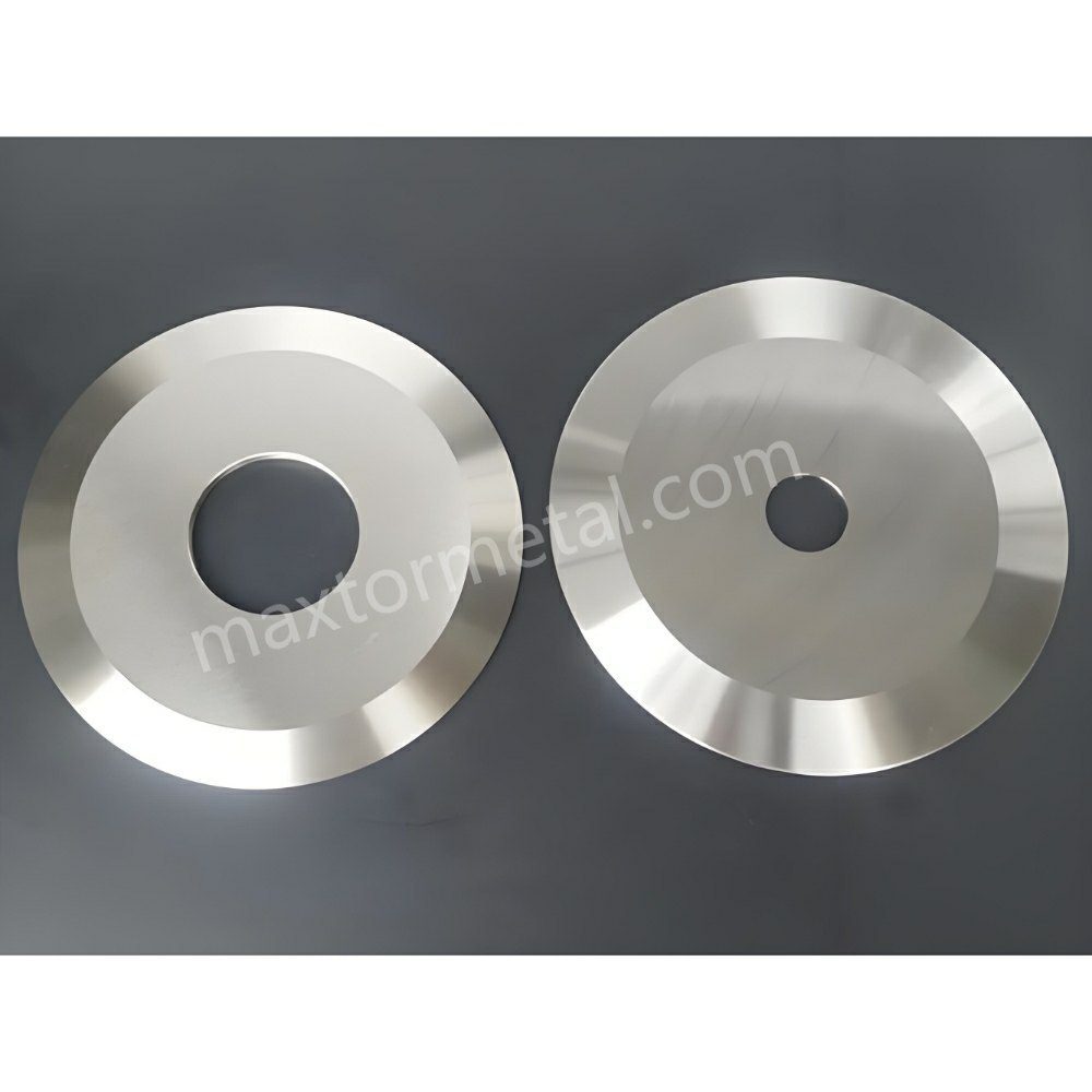
Os cortes em formato de serpente (também chamados de desvio ou deriva da linha de corte) acontecem quando a borda cortada não mantém um percurso reto e repetível: as faixas "caminham", oscilam ou se deslocam gradualmente, fazendo com que as camadas do rolo rebobinado percam o alinhamento central. Trate isso como um problema de estabilidade de todo o sistema de corte e rebobinamento, e não como um defeito de parâmetro único.
Esta checklist reflete a maneira como a maioria das equipes de manutenção e processos resolve esse problema no campo. Ela se baseia na sequência de diagnóstico usada pela equipe de engenharia de campo da Maxtor Metal ao solucionar problemas de por que um corte que parece adequado na configuração se torna instável em alta velocidade.
Conclusão principalSe os cortes em zigue-zague mudarem com a velocidade, o ganho de rolagem ou a posição na pista, comece isolando-os. de onde vem a força lateral (forças da faca vs. mecânica da teia vs. ar/estática) antes de começar a "mexer nos botões".“
Esta abordagem de diagnóstico baseada em sistemas é a estrutura que a equipe de engenharia de aplicação da Maxtor Metal aplica ao prestar suporte a clientes em linhas de corte de filmes e nãotecidos, onde o desvio das faixas resistiu a soluções de variável única.
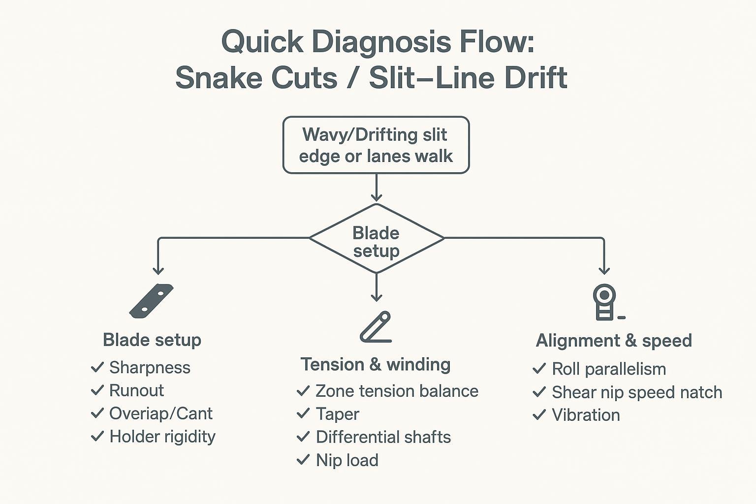
Fluxo de diagnóstico rápido
Quando suspeitar de problemas com a lâmina
- O problema é específico da faixa (uma ou duas faixas se deslocam enquanto as faixas vizinhas mantêm suas posições).
- Drift começa exatamente no ponto de corte, mesmo em baixa velocidade.
- Você trocou recentemente as facas, os espaçadores, os suportes ou mudou a posição das facas.
- A deriva apresenta um padrão repetitivo de "uma vez por revolução" (frequentemente associado à perda de convergência ou a um assento desalinhado).
Verificações rápidas:
- Verifique se a pilha de lâminas está limpa (sem resíduos, adesivos ou rebarbas nas faces).
- Verificação da excentricidade do indicador de mostrador nas faces do eixo/lâmina nas pistas que apresentam desvio.
- Confirme se a sobreposição/engajamento e a inclinação/alinhamento estão dentro da faixa esperada para o método de corte.
Quando suspeitar de tensão/enrolamento
- A deriva piora à medida que diâmetro do rolo aumenta.
- O defeito “se move” de uma faixa para outra com posição principal ou alterações na torre.
- Você vê telescópico, bordas soltas ou variação de dureza entre as faixas.
- A deriva melhora imediatamente quando você reduzir a velocidade ou alterar os pontos de ajuste de tensão.
Verificações rápidas:
- Comparar as tensões nas zonas de desenrolamento/meio da bobina/rebobinamento (reais vs. ponto de ajuste).
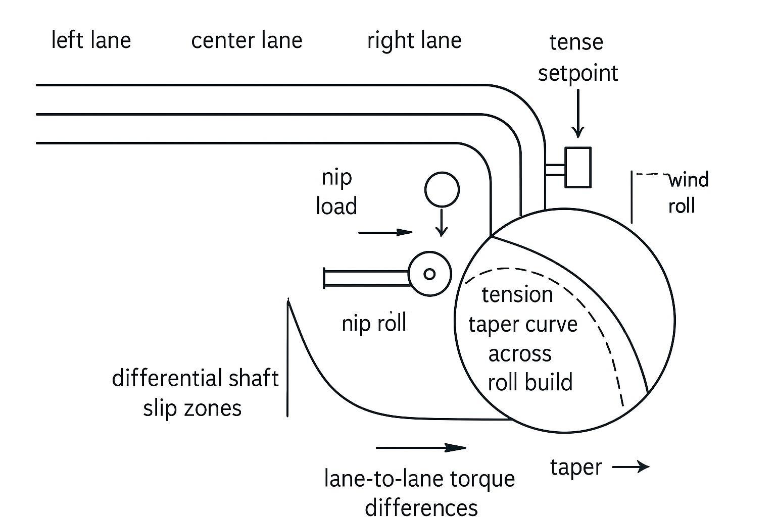
- Verificar o comportamento da tensão cônica ao longo da construção do rolo.
- Confirme se o deslizamento do eixo diferencial está funcionando corretamente em cada faixa (sem elementos travados).
Quando suspeitar de desalinhamento/velocidade
- A deriva piora após manutenção, substituição de rolamentos ou eventos de impacto/sobrecarga.
- A teia acompanha bem o fluxo a montante, depois muda após uma determinada inflexão ou alteração.
- Você ouve/sente vibração, vê marcas de padrão ou percebe oscilação da guia de borda.
Verificações rápidas:
- Verifique o paralelismo dos rolos e o equilíbrio dos pontos de contato; procure por desalinhamentos óbvios ou desgaste irregular.
- Ajuste de velocidade no ponto de contato da lâmina (velocidade da lâmina versus velocidade da bobina).
- Estado de conservação dos rolamentos e vibração (temperatura, ruído, espectro, se disponível).
matriz de causa raiz do corte da cobra
Utilize esta tabela como uma referência rápida de triagem antes de ajustar quaisquer configurações.
| Padrão de sintomas | Subsistema mais provável | Primeiro verifique |
|---|---|---|
| Deriva específica da faixa, começa na curva, presente em baixa velocidade. | Lâmina / suporte | TIR no eixo + faces de corte nas pistas afetadas; comparar com pistas estáveis. |
| A derrapagem piora à medida que a inclinação aumenta; melhora quando a velocidade diminui. | Enrolamento de tensão/diferencial | Tensão real versus tensão definida em cada zona; torque de deslizamento diferencial do eixo |
| A deriva surgiu após manutenção ou evento mecânico. | Alinhamento / rolamento | Paralelismo de rolamento; espectro de temperatura e vibração do rolamento |
| A deriva varia de acordo com o lote de rolos principal ou a posição na faixa (borda ou centro). | Perfil do material/calibre | Variação transversal da espessura da bobina; correlação da dureza entre faixas com a posição do cilindro matriz. |
| A deriva piora em alta velocidade e melhora quando a pressão de desacoplamento aumenta. | Arraste de ar / estático | Teste de redução de velocidade; verificação da continuidade da saída do ionizador e do aterramento. |
Configuração da lâmina e tolerâncias
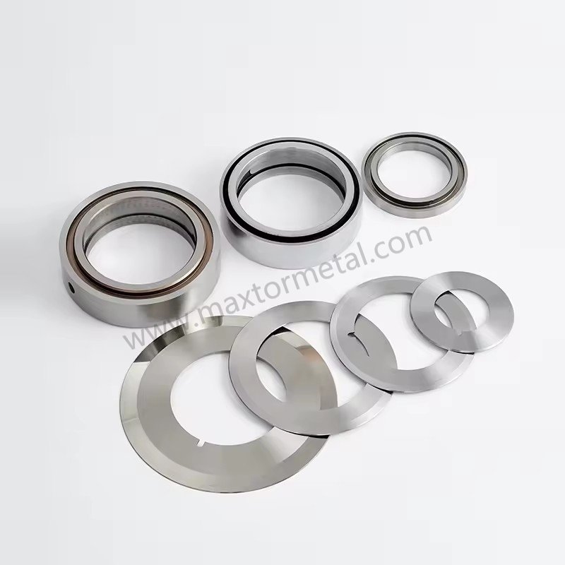
Nitidez, excentricidade, sobreposição, inclinação
Os cortes em forma de cobra geralmente começam como um pequeno desvio lateral repetível. Em muitas linhas, a maneira mais rápida de comprovar ou refutar a oscilação causada pela lâmina é medir o desvio radial onde ele é relevante.
- NitidezUma borda romba aumenta a força de corte e pode "direcionar" a bobina, especialmente em filmes finos a velocidades mais altas.
- Runout (TIR)Verifique os ombros do eixo, as faces do espaçador e as faces da lâmina — não apenas um ponto conveniente. Mantenha o desvio total indicado dentro de ≤0,025–0,050 mm (0,001–0,002 pol.) em toda a montagem. Os registros de inspeção de entrada do Maxtor Metal registram o TIR (Total Incremental Rate - Retorno Total da Inclinação) tanto na face da lâmina quanto na superfície de contato do eixo por lote, de modo que as medições de campo podem ser comparadas com os dados documentados de fábrica quando um problema de deriva aparece após a troca da lâmina. Para uma abordagem focada em medições do TIR axial e radial — incluindo protocolos de verificação de deriva de frio para quente e os mecanismos de defeito que cada modo de excentricidade produz — consulte Axial Runout, TIR dinâmico e qualidade da borda da fenda.
- Sobreposição/engajamentoDefina a sobreposição para o valor mínimo estável para seu método e material (normalmente começando em 0,5–1,2 mm / 0,020–0,045 pol. para corte longitudinal de filmes por cisalhamento padrão). Sobreposição excessiva pode mascarar temporariamente um problema mecânico, ao mesmo tempo que adiciona calor e carga lateral. Para filmes finos (PE/PP/PET <50 μm), a equipe de engenharia de campo da Maxtor Metal usa 0,50–0,75 mm como janela inicial e ajusta com base na qualidade da borda e na tendência da força de corte. Para uma análise completa de como a sobreposição, o ângulo de inclinação e a pré-carga da mola interagem durante a configuração, consulte Configuração com mola para corte longitudinal sem folga: controle de sobreposição, ângulo de inclinação e pré-carga.
- Cant / bondeMantenha os ângulos de inclinação dentro das especificações do fabricante (normalmente 0.25°–0.5°Se a máquina não estiver alinhada corretamente, você pode obter um corte que pareça aceitável na configuração inicial, mas que se torne instável à medida que as forças aumentam com a velocidade.
Para referências de corte por cisalhamento, o Guia de Referência de Corte Longitudinal da DIENES é uma base útil para entender como a sobreposição é tratada como uma variável controlada, em vez de uma configuração do tipo "quanto mais, melhor" (consulte Guia de Referência de Corte DIENES, 2ª ed. (PDF)).
Para linhas em que a escolha do revestimento também está sendo analisada — particularmente se os revestimentos de DLC ou PTFE afetam o comportamento de deriva e os intervalos de limpeza — consulte Guia de Seleção de Revestimentos DLC vs PTFE para Facas de Corte Longitudinal: Limite de Desgaste vs Transferência.
Rigidez do suporte e carga lateral
Mesmo com boas facas, um suporte flexível ou uma pilha que permita variação de carga lateral resultará em deslocamento em alta velocidade.
Cheques que geralmente dão resultado:
- Confirme se os suportes estão assentados de forma plana e fixados uniformemente em toda a pilha.
- Inspecione em busca de marcas de atrito, desgaste ou marcas de desgaste que indiquem micromovimentos sob carga.
- Verifique se os espaçadores não estão causando "empilhamento de tolerância" em um viés lateral (especialmente em montagens com várias pistas).
- Fique atento a aumentos na carga lateral que estejam correlacionados com a formação de rolos ou com o aumento da temperatura.
Os problemas de empilhamento de espaçadores geralmente remontam à precisão do ajuste do furo. Para a lógica de seleção de ajuste ISO 286 que estabelece a precisão de localização do furo no eixo — e como o TIR montado é verificado antes que um conjunto de espaçadores entre em produção — consulte Tolerância e excentricidade do furo central: otimizando os ajustes ISO 286 para facas de corte de alta velocidade.
A qualidade do fornecimento é mais importante para a estabilidade da configuração do que a maioria das equipes leva em consideração. Lotes de facas com dureza inconsistente ou variação dimensional introduzem uma variável que parece um problema de configuração, mas não responde a ajustes de configuração.
A norma Maxtor Metal documenta a dureza, a inspeção dimensional e os registros de rastreabilidade de lote/produção para todos os envios de facas de corte circulares — assim, quando um problema de desvio surge após a troca de uma faca, a investigação pode começar a partir de dados verificados do lote recebido, em vez de trabalhar retroativamente a partir dos sintomas.
Para projetos OEM/ODM em que as lâminas precisam ser compatíveis com suportes, eixos ou desenhos de engenharia antigos, a Maxtor Metal oferece suporte completo para especificações personalizadas, evitando que uma simples substituição de lâmina se transforme em um ciclo de tentativa e erro de geometria.
Para os cálculos que regem como a variação da espessura por lâmina se acumula em erro de largura de corte em uma configuração de múltiplas pistas — e uma disciplina de correspondência de espaçadores para minimizar o deslocamento axial na troca — veja Controle da tolerância cumulativa de espessura no corte longitudinal com múltiplas lâminas.
Opções: tesoura, navalha ou esmagamento
Escolha o método de corte adequado ao material e ao defeito que você está corrigindo:
Antes de selecionar o método de corte, a geometria do chanfro também precisa ser compatível com a rigidez do substrato — um chanfro simples que funciona bem em filmes finos de PE terá um comportamento diferente em laminados de PET. Para uma estrutura de seleção baseada na rigidez, que abrange perfis de chanfro simples, duplo e composto, consulte Biséis simples, duplos e compostos para facas de corte circular.
- Corte por cisalhamentoMelhor opção quando você precisa de qualidade de corte consistente e consegue manter a geometria (desvio, sobreposição, carga lateral). Tende a ser estável quando a base mecânica está correta.
- corte com lâminaSimples e preciso em filmes finos, mas sensível à condição da lâmina, ao posicionamento do sulco e à estabilidade da bobina. A posição do sulco é importante: se o sulco for muito raso em relação à espessura da bobina, a lâmina deflete lateralmente sob a tensão da bobina e o caminho de corte oscila com as mudanças de velocidade da bobina; se for muito profundo, a bobina envolve as bordas do sulco e o rastreamento torna-se sensível a qualquer assimetria de tensão lateral. A deriva também pode surgir rapidamente quando a bobina desliza sobre uma película de ar em alta velocidade ou quando a estática aumenta a adesão lateral às superfícies guia.
- Corte por esmagamentoPode ser tolerante em algumas configurações, mas também pode amplificar a oscilação quando as condições da borracha/bigorna variam ou quando o calor aumenta.
| Categoria de substrato/filme | Método recomendado | Principal vantagem | Fator de risco de deriva |
|---|---|---|---|
| Poliolefina fina (BOPP / PE) | Lâmina de barbear em ranhura / Tesoura | Borda da fenda limpa, poeira mínima | Deflexão da lâmina, flutuação do ar |
| Rígido / Alto Módulo (PET, PVC) | Corte por cisalhamento | Geometria de corte precisa, bordas limpas | Desalinhamento da lâmina, desalinhamento da inclinação |
| Filmes espessos/laminados | Cisalhamento / Esmagamento Pesado | Alta capacidade de força de cisalhamento | Variação de carga lateral, desgaste da lâmina |
Para uma estrutura baseada em DOE que mapeia como a profundidade de sobreposição e a folga lateral interagem nessas categorias de substrato — incluindo um modelo de compensação de Pareto entre a qualidade da aresta e a vida útil da lâmina — consulte Otimizando a profundidade de sobreposição e a folga lateral da lâmina circular..
Se você estiver observando cortes em formato de cobra apenas em determinados SKUs, reavalie se o método é compatível com a espessura do filme, o módulo de elasticidade, o coeficiente de atrito e a janela de velocidade.
Controle de tensão e rebobinamento
Pontos de ajuste e perfis
A tensão não é apenas um número — é um perfil que se desenvolve ao longo de diferentes zonas e ao longo do tempo. Um caminho de fenda estável depende de um estado de tensão estável na trama.
Regras práticas que se confirmam:
- Mantenha a tensão estável em toda a extensão. desenrolar → período do processo → rebobinar, e verificar as medições reais da célula de carga em relação aos pontos de ajuste do controlador. Deslocamentos de tensão superiores a ±5%–8% Os desvios do alvo são frequentemente suficientes para induzir o deslizamento lateral da fita e iniciar a deriva da linha de corte. A equipe de campo da Maxtor Metal usa essa faixa de ±5%–8% como limite de sinalização ao revisar os registros de tensão durante investigações pós-deriva em linhas de clientes.
- Use a tensão cônica intencionalmente; à medida que o diâmetro aumenta, a tensão geralmente precisa diminuir para evitar telescopagem, flambagem das bordas ou esmagamento do núcleo.
Para um ponto de partida baseado em normas para orientações sobre tensão em bobinas, a TAPPI publica documentos de orientação sobre tensão, tais como: DICA TAPPI 0200-01:2021 (diretrizes de tensão da web).
Eixos diferenciais e ponto de fixação
O enrolamento diferencial costuma ser o que diferencia "faixas que se comportam" de "faixas que se desviam". Quando as faixas aumentam de diâmetro em taxas ligeiramente diferentes, o sistema precisa de uma maneira controlada de equalizar o torque para que uma faixa não fique frouxa e comece a se desviar.
Verificações:
- Confirme se os elementos do diferencial realmente deslizam dentro da faixa de torque esperada.
- Verifique se a carga de pressão está equilibrada em toda a superfície do rolo; uma pressão irregular pode criar diferenças de tração entre as faixas.
- Analise a tensão cônica juntamente com as configurações diferenciais; se você aumentar a tensão à medida que o diâmetro aumenta, poderá sobrecarregar uma das pistas e desestabilizar o alinhamento.
Transições e tração
Muitos cortes em forma de cobra são "defeitos de transição":
- aceleração da velocidade de produção
- passagem de emenda
- transferência de torre
- A dureza dos rolos varia conforme o diâmetro aumenta.
Durante os períodos de transição:
- Confirme se a tração no percurso da teia é consistente (sem deslizamento repentino em um determinado ponto).
- Reduza a velocidade brevemente para diagnóstico. Se a deriva diminuir imediatamente, suspeite de problemas na aerodinâmica/tração/dinâmica estática antes de trocar as lâminas.
- Considere a oscilação da guia de borda como um sintoma — geralmente causada por oscilação de tensão, desalinhamento ou tração instável.
Alinhamento e correspondência de velocidade
Rolos, eixos e equilíbrio de pressão
Se a teia estiver sendo forçada lateralmente pela geometria, nenhuma configuração de lâmina a manterá reta de forma consistente.
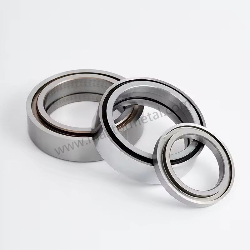
- Verificar o paralelismo dos rolos em relação ao eixo central da máquina.
- Inspecione as faces dos rolos quanto a conicidade, desgaste, contaminação ou danos.
- Verifique a distribuição da pressão de pinçamento; uma pressão desigual pode desviar a direção da teia.
Uma referência prática sobre os fundamentos do rastreamento da linha central e as causas do movimento lateral é a compilação de Walker na comunidade de manipulação de materiais em bobina (ver Linhas da Web: Walker sobre manipulação da Web (compilação em PDF de 2003 a 2014)).
Diferencial de velocidade no ponto de contato de cisalhamento
No corte por cisalhamento, a diferença de velocidade pode criar uma componente de força lateral no corte.
Lista de verificação:
- Verifique se a velocidade da superfície da lâmina corresponde à velocidade da bobina, conforme exigido pelo seu método de corte.
- Confirme se o acoplamento/folga da transmissão não está causando variações periódicas de velocidade.
- Se a deriva aumentar com a velocidade, mas não com a tensão, suspeite de correspondência de velocidade e vibração.
Saúde e vibração dos rolamentos
Problemas com rolamentos e vibrações frequentemente se disfarçam de "problemas de corte".
- Compare as temperaturas dos rolamentos esquerdo e direito.
- Preste atenção a ruídos cíclicos; verifique se há padrões.
- Se você tiver monitoramento de vibração, registre os espectros na cabeça de corte e rebobine.
Efeitos do material e do ar
Perfil e variabilidade do medidor
A variação na espessura da alma e a curvatura transversal criam uma tensão desigual ao longo das faixas. A alma geralmente se desloca para o lado mais estreito.
Verificações:
- Verificar o perfil do rolo recebido e a consistência da dureza.
- Procure por diferenças entre as faixas que se correlacionem com a posição de rolamento do veículo principal (borda versus centro).
- Se a deriva ocorrer apenas em determinados lotes, registre o ID do lote e os dados do perfil de medição em seu log.
Entrada de ar e deposição
O ar é um verdadeiro "elemento mecânico" em altas velocidades. Se a fita desliza sobre uma película de ar, a tração muda e o corte pode se desviar.
Verificações:
- Fique atento a oscilações e má sobreposição na rebobinagem.
- Utilize o sistema de sobreposição/pinçamento de forma eficaz (dentro dos limites da máquina) para reduzir o ar aprisionado.
- Como forma de diagnóstico, reduza a velocidade ligeiramente e observe se a oscilação diminui.
Ligação entre defeitos estáticos e de borda
A carga estática pode puxar o filme em direção aos guias/rolos, atrair poeira e tornar os pontos de separação instáveis — especialmente em filmes finos em velocidades mais altas.
Verificações:
- Verificar a continuidade da ligação/aterramento nos rolos principais.
- Inspecione as barras ionizadoras quanto à limpeza e ao desempenho.
- Acompanhe se o defeito piora em condições de baixa umidade.
When static-attracted dust is itself a product quality problem—not just a trigger for tracking instability—the blade-level root causes of dust generation (Ra, carbide microstructure, overlap-induced secondary rubbing) require a separate analysis. See Root-Cause Analysis of Slitting Dust Generation: Blade Flank Ra, Carbide Microstructure & Setup Tolerances.
FAQs:
P: O que causa os cortes em formato de serpente no corte de filmes?
R: Os cortes em serpentina geralmente decorrem de instabilidade lateral: forças na lâmina (desvio/runout, sobreposição, movimento do porta-lâminas), mecânica da tira/teia (desequilíbrio de tensão, problemas de rebobinamento diferencial), geometria (desalinhamento, pressão de nip irregular) ou dinâmica (aprisionamento de ar e eletricidade estática). O caminho mais rápido é isolar se o desvio começa na lâmina ou se surge durante o rebobinamento.
P: Como saber se o desvio da linha de corte é um problema de lâmina ou de tensão?
R: Se o problema for específico de uma faixa e começar logo no ponto de corte, mesmo em baixa velocidade, suspeite das lâminas, do desvio (runout) ou dos porta-lâminas. Se piorar com o aumento do diâmetro do rolo, melhorar ao alterar a tensão ou se mover de acordo com a posição do tubete, suspeite da tensão ou do rebobinamento diferencial.
P: O desvio/excentricidade da lâmina (runout) pode realmente causar o desvio das faixas de corte?
R: Sim. Mesmo um pequeno desvio (runout) pode criar uma força lateral repetitiva que desloca o caminho do corte. Meça o desvio no eixo (arbor), nas faces dos espaçadores e nas faces da lâmina com um relógio comparador e compare as faixas "boas" com as "ruins".
P: Quais configurações de tensão ajudam a parar o desvio da linha de corte em uma rebobinadeira cortadora?
R: Comece estabilizando a tensão em cada zona e verificando a tensão real por meio de medição. Em seguida, use um perfil de tensão cônica (taper) controlado para que a tensão não se acumule à medida que o diâmetro aumenta. As diretrizes publicadas pela TAPPI podem ajudá-lo a escolher uma faixa inicial, e depois você ajusta com base na dureza do rolo e na estabilidade das faixas.
P: Os eixos diferenciais evitam o desvio das faixas e o telescopamento (deslocamento dos rolos)?
R: Eles ajudam quando os diâmetros das faixas aumentam de forma desigual, pois o deslizamento controlado equaliza o torque para que nenhuma faixa fique frouxa e se desloque. Se os elementos de fricção travarem ou o torque for ajustado incorretamente, ainda podem ocorrer diferenças de dureza entre as faixas e desvios laterais.
P: Por que o desvio da linha de corte piora em velocidades mais altas?
R: Velocidades mais altas aumentam o aprisionamento de ar, amplificam a vibração e fazem com que pequenos desalinhamentos tenham um impacto maior. Se o desvio diminuir rapidamente ao reduzir a velocidade, suspeite da dinâmica do ar, da tração ou da eletricidade estática antes de alterar a geometria das lâminas.
P: Como posso reduzir o aprisionamento de ar ao rebobinar filmes?
R: Melhore a eficácia do rolo pressor/encosto (lay-on/nip) dentro dos limites da máquina, confirme a geometria da trajetória da tira até o rebobinamento e ajuste a tensão/taper para que a tira se molde ao rolo em vez de deslizar sobre uma película de ar. Um teste de redução de velocidade é uma maneira rápida de confirmar se o ar está causando a instabilidade.
P: Onde devo registrar os dados para evitar que os cortes em ziguezague (snake cuts) voltem a ocorrer?
R: Registre por ID do rolo e faixa: a montagem do jogo de lâminas (diâmetro externo, espessura, espaçadores), leituras de desvio (runout), configurações de sobreposição (overlap) e ângulo de inclinação (cant angle), tensões por zona e perfil de taper, tipo e configurações do eixo de rebobinamento, velocidade, status de mitigação de umidade/estática, e se o desvio mudou com a velocidade ou com o aumento do diâmetro do rolo.
Conclusão
Eliminar os cortes em formato de serpente (snake cuts) exige abandonar os ajustes empíricos e improvisados e adotar uma rotina de diagnóstico sistemática e baseada na física. Ao verificar sistematicamente a geometria da lâmina e a rigidez do porta-lâminas (mantendo um TIR ≤ 0,050 mm e o ângulo de inclinação e sobreposição adequados), estabilizar os perfis de tensão da tira nas zonas de rebobinamento e eliminar o desalinhamento dos rolos da máquina e o aprisionamento de ar em alta velocidade, as linhas de conversão de tiras podem alcançar estabilidade imediata na linha de corte.
Para transformar esse checklist em ganhos operacionais duradouros, as fábricas devem formalizar essas verificações em um procedimento operacional padrão (SOP). A implementação de uma ficha de preparação padronizada — com validações obrigatórias para as leituras de excentricidade (runout), sobreposição (overlap) e tensão — e o estabelecimento de uma rotina rigorosa de manutenção preventiva (PM) para porta-lâminas, eixos e rolamentos reduzem drasticamente a variabilidade nos setups de troca.
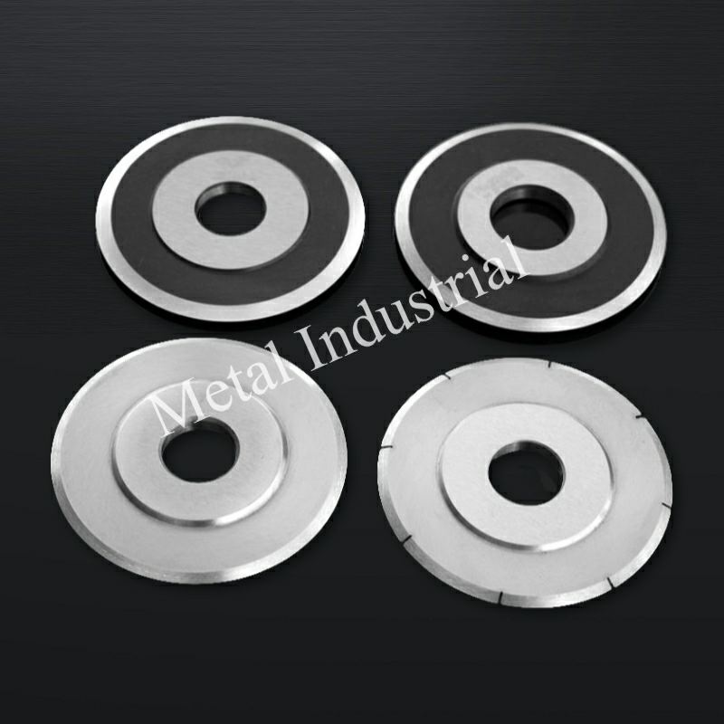
Para operações que padronizam as ferramentas em várias linhas de corte, a Maxtor Metal fornece lâminas circulares de corte com documentação dimensional e de dureza completa por lote, oferecendo suporte OEM/ODM quando as lâminas precisam corresponder aos desenhos existentes de eixos e porta-lâminas. Facas e lâminas circulares da Maxtor Metal Para referência de geometria e especificações.
Em última análise, medir o sucesso desses controles de estabilidade se resume a indicadores-chave de desempenho (KPIs). Operações de conversão de alto desempenho monitoram cinco KPIs principais para validar seu desempenho de corte:
- Taxa de sucata e resíduos (%)Redução direta do desperdício de filme aparado e de rolos rejeitados fora das especificações.
- Eficácia geral do equipamento (OEE)Velocidades de corrida mais elevadas e estabilidade de corte sustentada.
- Tempo de inatividade não planejadoMenos interrupções de impressão causadas por quebras de banda ou ajustes durante a execução.
- Vida útil da lâminaMaior durabilidade da ferramenta resultante da minimização da carga lateral e da sobreposição ideal.
- Reclamações de clientes sobre a qualidade do produtoMenor incidência de defeitos como ondulações nas bordas, telescopagem ou cortes em remessas de rolos acabados.
Autor / Revisor Técnico
Jerry Chu Especialista em Suporte Técnico (Serviço Pós-Venda)
Maxtor Metal
Jerry traz mais de 10 anos de experiência em aplicações em diversos setores, incluindo fabricação de papel, reciclagem/trituração de plástico, corte de metais e processamento de madeira. Especializado em solucionar desafios reais de corte longitudinal — como rebarbas, excesso de poeira e instabilidade de bordas — ele trabalha diretamente com equipes de engenharia de campo para otimizar o desempenho das ferramentas e a confiabilidade operacional.
- CertificaçõesProfissional Certificado em Manutenção e Confiabilidade (CMRP), Profissional em Gerenciamento de Projetos (PMP®)
- EspecialidadesSolução de problemas de corte longitudinal no local, projeto de geometria de lâmina personalizada e desenvolvimento de procedimentos operacionais padrão (POP) para manutenção preventiva.

 English
  Spanish
  Italian
  French
  Portuguese
  Russian
  German
  Arabic
  Hindi
Hindi  Vietnamese
  Indonesian
  Japanese
  Korean