


スリッターにおけるカエリ(バリ)の低減は、一見小さな現場課題でありながら急激な we-cost(コスト増)を招く代表例です。バリの発生は顧客クレームを誘発し、后工程での成形不良(曲げ・ロール成形等)を引き起こすだけでなく、刀具寿命(ナイフライフ)を静かに缩める原因となります。
このハンドブックは、炭素鋼、AHSS、ステンレス、アルミニウムを処理するコイルスリッターラインにおける10年以上の現場トラブルシューティング経験に基づき、Maxtor MetalのテクニカルサポートスペシャリストであるJerry Chuによって編纂されました。Maxtor Metalのアプリケーションエンジニアリングチームによる査読を経て、規律あるセットアップウィンドウ、迅速な根本原因の特定、そして一貫した測定を成功へのアプローチとする、実用的かつ検証第一の精神で執筆されています。.
お客様のラインでローラーシャー刃(または同等のスリッターナイフシステム)を使用している場合でも、以下の原則が適用されます。すなわち、切断を制御された破断/せん断現象として捉え、バリの発生に実際に影響を与える少数の変数を確実に固定することです。ローラーシャー工具に特化した材料選定、クリアランス設計、および故障モード診断については、Maxtor Metalの ロータリースリッターナイフおよびローラーシャー刃エンジニアリングガイド.
本ハンドブックの構成内容
根本原因(クリアランス/オーバーラップ、刃物の状態、アライメント、速度、潤滑、張力)の特定、材質グループごとの初期設定範囲の定義、および検査、合格基準(公差帯)、ROI追跡の標準化を通じて、切断端面のカエリ(エッジバリ)を低減するための現場およびエンジニアリング向けリファレンスです。これは顧客の図面要求仕様を代替するものではありません。最適条件に迅速に収束させるために活用し、最終的には自社の工程能力(Process capability)と照らし合わせて検証してください。
対象読者
異なった鋼種や板厚に応じてスリッティング品質を微調整するプロセスエンジニア、アーバー(刀軸)の状態、偏芯・面振れ(ランアウト)、セットアップ全体の締め付け精度(スタックの整合性)を管理する保全リーダー、切断端面品質と設備稼働率(アップタイム)のバランスを取る製造管理者、そして刃物・スペーサーの選定および再研磨コスト(ROI)を評価する技術用度・采购担当者。
稼働中のラインでの活用方法: 最初に測定の厳格化(測定規格の統一)を確認する → 設定変更を行う前に根因分析マトリクスを用いて最も影響度の高い要因(レバー)を特定する → 材質別セットアップ範囲を初期条件として適用し、微小な刻み幅で調整を行う → 設定変更後は必ず短尺の検証ストリップ(切断サンプル)を通し、再測定を実施する。
追跡すべき重要指標
板厚に対するカエリ(バリ)高さ比率(および顧客指定時の絶対高さ) · 幅公差および寸法ドリフト(スペーサー/スタックの累積誤差を含む) · 稼働率/OEEへの影響(段取り替え時間、刃物交換、計画外停止) · 工具寿命(1研磨あたりの通板吨数、1セットあたりの通板吨数、および損傷形态:摩耗 vs マイクロチッピング)。
主なポイント: 図面要求(Print)と照合して記録・検証されていないバリ改善効果は、持続させることができません。
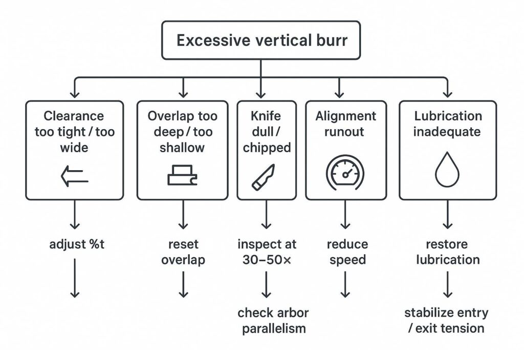
スリッターのカエリ(バリ)低減に向けた根本原因マトリックス
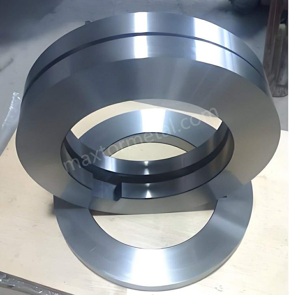
クリアランスおよびオーバーラップのエラー
水平クリアランスと垂直オーバーラップは、最も効果が高く、最も迅速にテストできる変数であるため、まずはここから確認してください。業界の実践的なガイダンスでは、バリの発生原因は一貫して不適切なクリアランスや過剰なオーバーラップに関連付けられています。.The Fabricator:「コイルスリット加工におけるスリットイン(巻き込み)トラブルを回避する方法」(2006年)
確認事項(順に):
- 水平クリアランス(%t):狭すぎるとエッジが擦れたり丸まったりし、広すぎるとせん断ではなく引きちぎられてしまいます。(一般的には スリッターナイフのクリアランス率.)
- 垂直オーバーラップ:深すぎるとバリやエッジの損傷が増加し、浅すぎると切断が不安定になります。(お客様の スリッターのオーバーラップ設定 も%tと同様に重要です。)
- バリの偏り:片方のエッジのバリがひどい場合は、単に「%tの誤り」だけでなく、アライメントやスタックの問題を示していることがよくあります。“
corrective levers:
- クリアランスを 被削材に応じた初期設定範囲 にリセットします(「被削材別のセットアップウィンドウ」を参照)。.
- 切り込み深さに伴ってバリが増加する場合は、オーバーラップを段階的に少しずつ減らします。.
- 条間でバリのパターンが一貫していない場合は、スタックの対称性とスペーサーの状態を再確認します。.
For the full mechanics behind overlap-to-clearance coordination — including burnish/break ratio interpretation, material-specific penetration windows, and arbor positioning best practices — see the rotary knife overlap settings guide.
誤った対策を講じていることを示す故障モード:
- バリが一時的に減少するが数分以内に戻る → 刃先の状態、または異物・熱の問題。.
- 低速時はバリの状態が良いが、生産速度に達すると悪化する → 張力の安定性、潤滑、または動的アライメントの問題。.
刃の鋭さ、形状、およびコーティング
バリは、セットアップの問題を装った刃の状態の問題であることがよくあります。.
確認事項:
- 刃先Rの増大 (摩耗・鈍化)および 微小チッピング (特にAHSSやステンレスにおいて)。.
- 形状の一貫性 セット全体における一貫性(ベベルの対称性、端面振れ)。.
- 凝着 / ピックアップ ステンレスやアルミニウムにおける発生(「突発的なバリ」の一般的な原因)。.
corrective levers:
- 検査のタイミングを前倒しする:品質が低下する前に刃先を確認します。.
- 「摩耗によるバリ」と「チッピングによるバリ」を区別する:摩耗は緩やかに進行しますが、チッピングは急激な変化をもたらします。.
- 故障モード(凝着か、それとも摩耗か)に応じたコーティング選定ロジックを適用します。.
アライメント、速度、潤滑、および張力
クリアランスやオーバーラップが適正範囲内にあり、刃の状態も良好な場合、次の段階は「ラインの動きによって切断位置が変動している」可能性です。“
確認事項:
- アライメント:.
- スピード:.
- 潤滑:液剤の塗布を主要なエッジ制御変数として扱います。アルミニウムやステンレスのスリット加工では、フェルトパッドやミストノズルを介して軽質合成油や揮発性油を塗布することで、摩擦を低減し、刃面への被削材の付着(凝着)を防ぎます。厚物炭素鋼では、境界潤滑剤がせん断領域の摩擦熱を放散させ、刃先の熱軟化の進行を抑制します。.
- 張力: 入側/出側の張力が不安定になると、ストリップの歪み、バタつきの発生、およびエッジの損傷を引き起こす可能性があります。.
参考資料:業界団体の会報によると、スリッターの剛性、水平/垂直クリアランス、および再研磨の管理に注意を払うことで、バリの高さを最小限に抑えることができます(Australian Steel Institute, Technical Bulletin TB-F2)。.
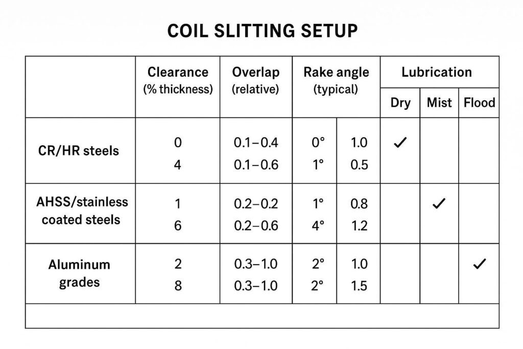
材質別クリアランス・条件設定範囲
これらは Windowsを起動しています セットアップ時間を短縮し、試行錯誤を減らすためのものです。常に顧客の図面、およびラインの剛性、ナイフ径、アーバの状態に照らし合わせて検証してください。キーワードを意識した表現が必要な場合、このセクションは実用的な 材質別のスリッティング・セットアップ・ウィンドウ.
| 被削材グループ | 水平クリアランス (%t) | 垂直オーバーラップ (mm / in) | 主な重点分野 |
|---|---|---|---|
| 冷延/熱延炭素鋼 | 8% – 12% t (標準値: ~10% t) | +0.25 mm〜+0.50 mm (+0.010″〜+0.020″) | せん断・破断面比率のバランス調整、過度なオーバーラップの回避 |
| AHSS / ステンレス鋼 | 10% – 15% t (高張力材: ~12% t) | +0.10 mm〜+0.30 mm (+0.004″〜+0.012″) | 微小チッピングの防止、刃先Rおよび凝着の監視 |
| アルミニウム&軟質合金 | 5% – 8% t (厳密なアライメントが必要) | +0.05 mm〜+0.20 mm (+0.002″〜+0.008″) | 耐凝着コーティング (DLC)、凝着(ピックアップ)およびかじりの防止 |
冷延/熱延鋼板
初期目標:引きちぎりを最小限に抑えた安定したせん断帯の形成。.
標準的な炭素鋼は延性と引張強さのバランスが優れており、従来の「せん断1/3、破断2/3」の端面比率が適用可能です。8%–12% tのクリアランス範囲内で操業することで、過度なエッジのダレや深い引きちぎりを発生させることなく、クリーンな破断移行を実現します。.
- クリアランス:推奨範囲の中間値(~10% t)から開始し、バリが最小になるよう微調整します。.
- オーバーラップ:適度な値に設定。「保険としての深いオーバーラップ」は避けてください。“
- 速度:低・中速域でバリが安定した後にのみ速度を上げてください。.
- 潤滑:熱による刃先劣化を防ぐため、一貫した潤滑管理を行ってください。.
実務上の注意:ASIのTB-F2会報では、推奨クリアランスが要求(一般生産か最小バリか)によって異なることを示しており、最適なクリアランスがバリを低減することを強調しています。.オーストラリア鉄鋼協会 技術速報 TB-F2 (鋼板および鋼帯のせん断およびスリット加工)
プロのヒント: 生産性向上のために設定範囲を広げる場合は、変更内容(クリアランス、オーバーラップ、速度、張力)を必ず記録してください。そうしないと、次回「同じ材料」を通板する際に、実際には同じ条件になりません。.
AHSS、ステンレス、およびめっき鋼板
初期目標:バリを抑制しつつ、チッピングやエッジ割れを防止する。.
高張力AHSSや加工硬化しやすいステンレス鋼は、極めて高い降伏強度と低い伸びを示します。高強度合金特有の急激なせん断破断に対応しつつ、刃先にかかるピーク側方スラスト力を緩和して微小チッピングを防ぐためには、広めのクリアランス(10%–15% t)が不可欠です。.
- クリアランス:管理された範囲内(~12% t)に維持し、極端な設定は避けてください。.
- オーバーラップ:控えめに設定。深すぎるとエッジ損傷が急増する原因になります。.
- ナイフの状態:検査頻度を上げてください。微小なチッピングが品質を左右します。.
- 潤滑:極めて重要として管理してください。凝着(ピックアップ)や熱がトラブルの主な引き金となります。.
- 張力:最大生産量よりも安定性を優先してください。.
アルミニウム材
初期目標:凝着(ピックアップ/かじり)を防止し、切断面の仕上がりを保護する。.
アルミニウムや軟質非鉄金属は延性が高く、材料が凝着(かじり)しやすい傾向があります。狭めのクリアランス(5%–8% t)を設定することで、軟質なストリップが引きずられて刃先に巻き込まれるのを防ぎ、連続的な重度のロールオーバーバリの発生を抑制します。.
- クリアランス:通常、鋼材よりも狭く設定(5%–8% t)しますが、これはアライメントが正確に調整されている場合に限ります。.
- オーバーラップ:控えめに設定。不要な深さは避けてください。.
- 潤滑:合金の種類や表面品質の要求に適した方法を採用してください。.
- ナイフの表面状態:凝着(ピックアップ)に注意してください。わずかな付着物がバリの大きさを劇的に変化させます。.
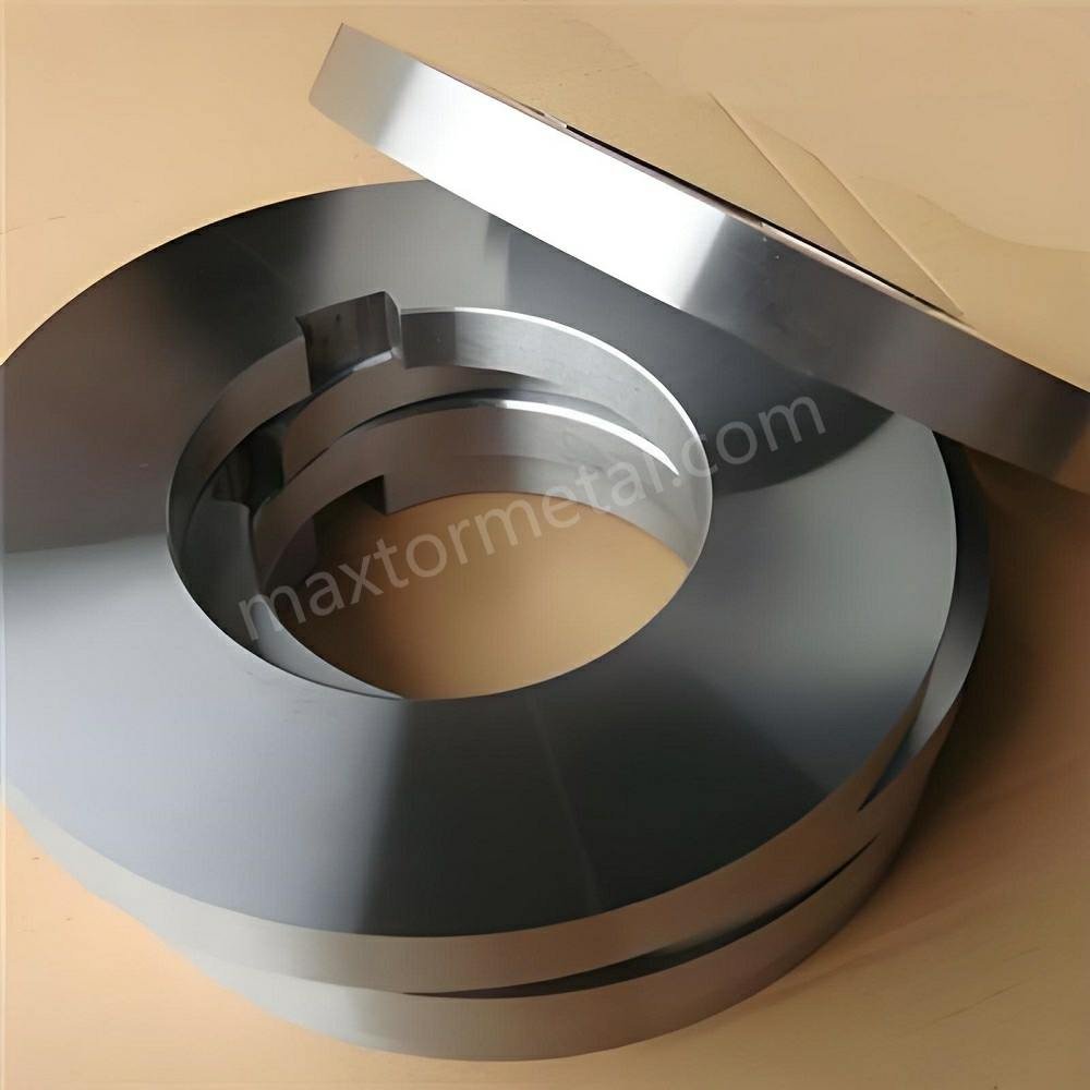
刃物(ツール)の選定とメンテナンス
ナイフ鋼材および表面コーティング
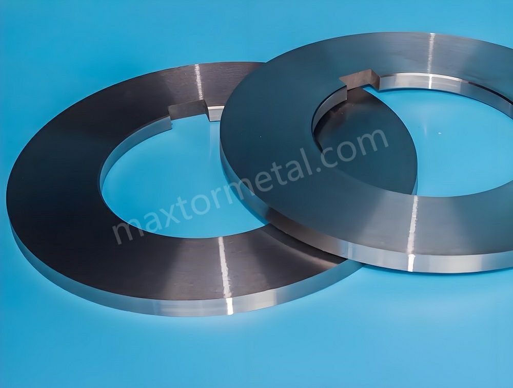
Maxtor Metalの標準コーティング選定は、「破損モード優先」のロジックに従います。 DLC は、かじりや凝着(ピックアップ)が主なリスクとなる場合の標準的な選択肢です(ステンレス鋼、アルミニウム、およびめっき基材)。; TiAlN は、刃先の磨耗や熱が支配的な要因となる場合に選択されます(高速AHSS加工、厚物炭素鋼)。異種材料が混在するラインでは、Maxtor Metalのアフターサービスチームは通常、別々のナイフセットで破損モードごとに1つのコーティングをテストし、標準化する前に3〜5回の生産ランにわたって研磨間通板量(tons-per-grind)と刃先状態の傾向を比較することを推奨しています。.
再研磨間隔と刃先検査(30–50×)
実用的な基準は、以下での検査です。 30–50×の倍率 バリの許容値および被削材の難削度に応じたスケジュールで。.
事後的な研磨(バリのクレームが発生してから研磨する)から計画的な予防保全へと移行するには、実用的な通板量(トン数)のしきい値を使用して、再研磨頻度の基準を設定します。
| 被削材の難削度 | 標準的な通板量間隔(1セットあたり) | 30–50×での検査ポイント |
|---|---|---|
| 標準炭素鋼(CR/HR) | 200 – 400トンごと | 均一な刃先Rの増大(<0.03 mm) |
| AHSS / 高張力合金 | 100 – 180トンごと | 微小チッピング、ノッチ摩耗、刃先欠損 |
| ステンレス鋼 / アルミニウム | 120 – 250トンごと | 金属の凝着/かじり、ランド面の凝着物 |
標準化すべき項目:
- 検査のトリガー:段取り替え後の最初のコイル、ライン速度上昇後、およびバリが増加傾向にある.
- 刃先基準:刃先Rの増大、微小な欠け、ピックアップ、および不均一な摩耗。.
- 再研磨ルール:バリが「アラーム」となる前に再研磨を行う。発生した後では遅い。.
失敗(不具合)の様相:
- バリが顧客仕様から外れて初めて再研磨を行う → プロセスは事後対応的であり、制御されていません。.
スペーサーの精度とスタックの完全性
スペーサーとスタックの管理は幅公差の問題であり、 そして バリの問題でもあります。.
標準化すべき項目:
- スペーサーの検証とトレーサビリティ(測定された厚さ、摩耗履歴)。.
- スタック構築手順(清浄度、トルク管理、一貫した向き)。.
- 複数刃セットアップにおける累積誤差の定期的なチェック。.
失敗(不具合)の様相:
- 運転中の幅の変動、および条ごとのバリのばらつき → スタックの完全性と振れが疑われます。.
スペーサーの公差仕様、ゴムリングの圧縮目標、および再構築チェックリストのテンプレートについては、以下を参照してください。 精密スリッティングスペーサーおよびゴムリングガイド.
芯出し(アライメント)とテンション制御

アーバの平行度および振れのチェック
アーバが平行でない場合、または振れが制御されていない場合、クリアランスは「角度ごとに異なる」ものになります。“
実地確認:
- 関連する表面(アーバ、刃先端面座)の振れを測定します。.
- 有効幅全体にわたる平行度を確認します。.
- メンテナンス後、およびツーリングの衝突後に再確認します。.
ダイヤルゲージのセットアップ、TIR(総振れ)許容基準、およびブルーチェック(当たり確認)プロトコルをカバーする、体系的な振れ検証手順については、以下を参照してください。 OEMスリッターナイフの図面:スピンドル嵌合監査、ISO公差、TIRゲート.
パスライン、ガイド、およびセパレーターのセットアップ
ストリップのガイドが不適切であると、横方向の力が加わり、有効な切断状態が変化する可能性があります。.
セットアップの重点:
- ガイドがライン全体で中央に配置され、一貫していること。.
- 二次バリの原因となるエッジ接触を防ぐために、セパレーターが整列していること。.
- ストリップが刃物に向かって「蛇行」していないことを確認します。.
入側/出側張力およびリコイラーの設定
張力の不安定さは、刃物の問題のように見えることがあります。.
標準化すべき管理項目:
- グレードおよび板厚ごとの入側/出側張力設定値。.
- ストリップのバタつき(ストリップフラッター)を誘発しない速度変更(加減速レート)の手順。.
- スループット(生産量)よりもバリ制御を優先すべき場合の明確なルール。.
測定・受入検査・ROI(投資対効果)追跡
バリの測定と記録
バリを確実に低減するために、測定をプロセスパラメータのように定義します。
- 測定位置(エッジの位置およびコイル始端/終端からの距離)
- サンプリング頻度(コイルごと、スリットごと、段取り替えごと)
- 測定方法(顕微鏡、光学測定、または輪郭形状測定)およびオペレーターのトレーニング
最低限記録すべき項目:
- 材料グレード、板厚、コーティング
- クリアランス(%t)およびオーバーラップ設定
- ナイフセットID、再研磨回数、検査結果
- ライン速度、潤滑モード、張力設定値
- バリ高さの結果(およびスクラップ/手直し事象)
許容範囲と文書化
許容範囲は、暗黙の了解(属人的な経験則)ではなく、顧客の図面に合わせます。.
図面/仕様書の文言については、, ISO 13715 が、技術文書において形状の定義されないエッジ(バリやアンダーカットの指示を含む)を指示および寸法記入するための主要な国際基準です。主要な製造業および鉄鋼業界団体による業界実務ガイダンスでは、生産稼働前に明確なエッジ状態の公差を設定することが一貫して強調されています。.
実践的なアプローチ:
- 顧客の要求事項を、測定可能な許容範囲(絶対値または%t)に変換します。.
- 該当する場合は、面の指定(どちらの側にバリが許容されるか)を含めます。.
- 誰が測定したか、どの方法か、校正状態はどうであるかなど、監査可能な記録を維持します。.
このプロセスの一環として、貴社のチームがリビルドチェックリストとバリ傾向ログを使用している場合、Maxtor Metalの スリッティングスペーサーおよびリングリビルドテンプレートセット は、すぐに使用できるフォーマットを提供します。.
ROI/TCOテンプレートと基準値設定(ベースライニング)
バリの低減は、単にエッジの「見た目が良くなる」だけでなく、トン当たりの総コストを削減できて初めて投資回収が可能です。変更を加える前に、以下の基準値を設定してください。
- エッジ品質に起因するスクラップおよび手直しコスト
- 段取り替えや計画外停止によるダウンタイム時間(分)
- トン当たりのナイフコスト(再研磨や特急注文を含む)
- バリまたはエッジ状態に関連する顧客からの返品/チャージバック
次に、セットアップウィンドウを適用した後の変化(デルタ)を追跡します。
- バリ適合率(直行率)
- 研磨当たりの通板量(トン)およびナイフセット当たりの通板量(トン)
- 段取り替えごとのセットアップ時間
セットアップウィンドウの改善と並行して、ナイフ材質のROIケースを構築する場合は、 ロータリー式スリッターナイフの投資対効果(ROI)ガイド が、AHSS、ステンレス、およびアルミニウムにおけるPM-HSSと工具鋼のトレードオフをカバーするトン当たりコストモデルを提供します。.
ケーススタディ:自動車プレス部品サプライラインにおけるバリ低減
5mmのAHSS(DP780)を加工するある自動車向けティア1コイルスリット工場では、材料板厚の12%を超えるエッジバリが繰り返し発生し、顧客の不合格率の高止まりと頻繁なナイフの微小チッピング(マイクロチッピング)に悩まされていました。.
Maxtor Metalの技術サポートチームと共同で開発したセットアップウィンドウおよび検査プロトコル(クリアランス/オーバーラップの再設定、倍率ベースの検査スケジューリング、および初物確認の徹底を含む)を導入することにより、以下の成果が得られました。
- パラメータ調整:水平クリアランスを管理されていなかった18% tから厳格に管理された11% tに再設定し、垂直オーバーラップを+0.60 mmから+0.20 mmに縮小しました。.
- ナイフのメンテナンス:不具合発生後の研磨から、150トン通板ごとの40倍光学検査へと移行しました。.
- 結果:平均バリ高さが以下のように低下しました。 18 mm (12% t) に <0.05 mm (3.3% t), となり、ISO 13715の仕様を満たしました。再研磨当たりの通板量(トン)は 42%, 増加し、エッジ欠陥による年間のスクラップコストは estimated $30,000–$45,000 (based on material cost and reject rate data provided by the facility; anonymized and range-normalized).
- 制限事項: These results were observed under stable incoming coil flatness and arbor runout below 0.010 mm. Lines with worn bearings, uncontrolled tension, or mixed operator discipline may see smaller gains from setup window changes alone.
FAQs:
Q: コイル・スリッティングラインでカエリ(バリ)を最も早く低減する方法は何ですか?
A: まずクリアランス(横隙)とオーバーラップ(縦重なり量)の調整から着手し、次いで刃先状態を30〜50倍の拡大鏡で確認します。速度変化に伴ってバリの状態が変わる場合は、張力(テンション)の安定性と潤滑状態を点検してください。
Q: スリッターナイフのクリアランス(横隙)の initial %(初期設定比率)はいくらから始めるべきですか?
A: 固定の%数字ではなく、被削材の材質特性に応じた初期条件範囲(Setup window)を設定します。範囲の中央值からスタートし,短尺の検証ストリップ(切断サンプル)を通した後,バリ高さを記録しながら微小な刻み幅で調整を行ってください。
Q: 縦方向のオーバーラップ(切り込み深さ)を大きくすれば、常にバリ(カエリ)は低減しますか?
A: いいえ。過度なオーバーラップは逆にバリを増大させ、刃先を損傷させる原因となります。オーバーラップは管理変数として扱い、切り込み深さを増した際にバリが増加する場合はオーバーラップ量を減らしてください。
Q: カエリ(バリ)高さを再現性高く測定するにはどうすればよいですか?
A: 定義された測定方法(顕微鏡/光学測定器/表面粗さ・形状測定器)、固定されたサンプリング位置、および標準化された記録用テンプレートを使用します。図面で許容されている場合は、バリ高さを板厚に対する比率(%)として報告してください。
Q: 片側の切断端面のカエリ(バリ)がもう片侧よりも酷くなるのはなぜですか?
A: この現象は、軸のアライメント不良、面振れ・偏芯(ランアウト)、またはスタック/スペーサーの精度不良により、横隙(クリアランス)が左右不均一になっていることを示唆しています。アーバー(刀軸)の平行度、刃物の座面着座状態、およびスペーサーの厚み精度を再点検してください。
Q: スリッターナイフ(円形丸刃)の点検および再研磨(Regrind)はどのくらいの頻度で行うべきですか?
A: 許容バリ高さ規格および通板材料の加工負荷(高张力钢等)に応じた周期で、30〜50倍の拡大鏡を用いて点検を行ってください。バリがアラーム条件(限界値)に達する前に予防的な再研磨を実施することが重要です。
Q: ステンレスやアルミニウムのスリッティング加工で、凝着(ギャリング/galling)を防止する最適なコーティングは何ですか?
A: 凝着や溶着(ピックアップ)のリスクを軽減するため、DLC(ダイヤモンドライクカーボン)コーティングがよく選ばれます。御社の潤滑条件およびライン速度のもと、刃先への金属溶着、バリの発生傾向、および再研磨1回あたりの通板トネージ(TONS-PER-GRIND)をモニタリングして効果を検証してください。
Q: 製造(製造現場)および購買部門に対して、バリ低減によるROI(投資対効果)をどのように証明すればよいですか?
A: まずスクラップ(不良率)/手直し工数、設備停止時間(ダウンタイム)、およびトン当たりの刃物コストのベースライン(現状データ)を算出します。その上で、標準化されたセットアップ条件および統一された測定基準を用いた実証テストを実施し、データを比較検証してください。
結論
- Summarize diagnostic priorities and parameter windowsDiagnostic priority is simple: (1) clearance/overlap, (2) knife condition, then (3) alignment/tension/lubrication. Use the setup windows as starting ranges, tune with small changes, and avoid simultaneous multi-variable “guessing.”
- Reinforce measurement discipline and verification against customer printsBurr control only holds if you measure it the same way every time and verify acceptance against the customer print language—especially when edges are specified using formal indication practices such as ISO 13715 (as described in the Acceptance bands section above).ISO 13715:2017 — ISO catalog page
- Next steps: pilot runs, data logging, and continuous improvementRun a short pilot on one representative grade, lock the logging fields, and convert your best settings into a controlled setup window.This is also where Maxtor Metal‘s after-sales support fits most naturally: if you want a second opinion on your regrind interval, coating selection, or clearance window for a specific material, Maxtor Metal’s technical support team can review your current setup parameters and edge inspection findings — and provide documented recommendations tied to your material grade, line speed, and knife geometry.Keeping tooling decisions, regrind intervals, and acceptance bands tied to the same dataset is how improvements survive operator changes and material mix shifts.
Author & Technical Reviewer
ジェリー・チュウ
Technical Support Specialist, After-sales Service | Maxtor Metal
Jerry Chu is Technical Support Specialist at Maxtor Metal, with over 10 years of coil slitting troubleshooting experience across carbon steel, AHSS, stainless, and aluminum processing lines. His field work focuses on root-cause isolation for burr and edge quality failures — translating setup window discipline, knife inspection protocols, and regrind scheduling into measurable reductions in scrap, rework, and unplanned downtime. The diagnostic framework and setup windows in this handbook reflect the approach Jerry applies in Maxtor Metal’s after-sales technical support engagements. Certifications: PMP (Project Management Professional), CMRP (Certified Maintenance & Reliability Professional).

 English
  Spanish
  Italian
  French
  Portuguese
  Russian
  German
  Arabic
  Hindi
Hindi  Vietnamese
  Indonesian
  Japanese
  Korean