

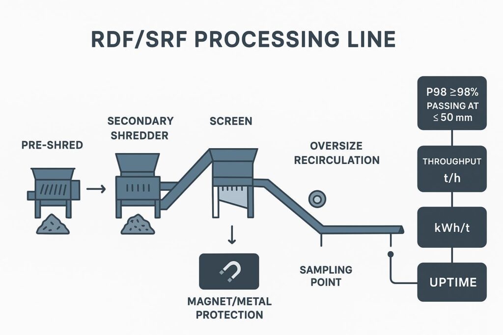
길게 찢어진 불량품(Long-strip rejects)은 RDF/SRF 생산 시 숨겨진 비용 손실 요인입니다. 이는 단순히 스크린 체 가름 규격을 통과하지 못하는 데서 끝나지 않고, 재순환 부하를 늘리고 로터 감김(Wrap) 리스크를 높이며, 처리량(Throughput)을 떨어뜨리는 동시에 톤당 전력 소비량(kWh/t)을 지속적으로 증가시킵니다. 본 아티클에서는 스크린 기반 입도 제어 라인에서 길게 찢어진 원단을 근본적으로 제거하고 98% 이상(P98)의 통과율로 ≤50 mm 입도를 안정적으로 달성하기 위한 엔지니어링 솔루션을 제시합니다.
요약:
- 목표: 98% 이상의 통과율(P98)로 ≤50 mm 입도를 달성하기 위해 길게 찢어진 불량품(Long-strip rejects) 근본 제거.
- 적용 범위: 2차 파쇄(Secondary shredding), 스크린 기반 입도 제어, RDF/SRF 파쇄 처리 효율 향상.
- 표준 규격: EN ISO 21640; 체 가름 분석 기반 수용 및 보고.
- 핵심 제어 요소: 나이프 형상, 빗형 고정날(Comb stator), 스크린/OAR, 전단 간격(Shear gap), 투입 제어, 품질 보증(QA).
핵심 요약: 긴 스트립 발생은 시스템적 문제로 다루어야 합니다 (형상 + 스크린 처리 용량 + 간격 제어 + 피드 안정성). 실제 혼합 폐기물의 변동성 속에서 단 하나의 요소만 해결해서는 P98 기준을 유지하기 어렵습니다.
근본 원인
유연한 필름 및 섬유류
유연한 폴리머 및 섬유질 성분(필름, 톤백 스크랩, 섬유, 밴드 스트랩 등)은 늘어나고, 접히며, 그대로 “끌려 들어가는” 경향이 있습니다. 절단 영역에서 짧은 입자로 분쇄되는 대신, 미끄러지거나 로터에 올라타 결국 긴 리본 형태로 배출될 수 있습니다.
저속 전단식 파쇄(size reduction)에서는 대상 물질이 크기 제한 스크린을 통과할 때까지 반복적인 전단/재물림 루프 내에 머물도록 하는 것이 목표입니다. 유연한 재질이 이러한 루프를 회피할 경우(늘어나거나 감김으로써), 긴 스트립이 발생하고 입자 길이 분포가 불안정해집니다.
필름/섬유류의 거동이 지배적임을 나타내는 실질적인 징후:
- 수분이 많은 원료, 겉보기 밀도가 낮은 원료가 투입되거나 필름 비율이 증가할 때 긴 스트립이 급증합니다.
- 처리량은 비례해서 늘지 않으면서 동력 소비량(kW)만 증가합니다.
- 스크린 막힘(blinding)이나 로터 감김 현상이 스트립 길이 편차와 직접적인 상관관계를 보입니다.
하드웨어를 변경하기 전 간단한 현장 테스트: 대표적인 “스트립”을 손으로 잡아당겨 봅니다. 찢어지기 전에 심하게 늘어난다면, 커터와 스테이터(고정 칼날) 접촉면에서 더 확실한 포착 및 재물림이 필요하다는 신호입니다.
스크린 캐리오버(carryover) 및 개구율(open area)
스크린 크기에 제한을 받는 2차 파쇄기에서 스크린은 단순한 크기 분류 장치 그 이상입니다. 이는 입자가 배출되기 전까지 얼마나 많은 재절단 기회를 얻는지를 결정합니다.
스트립 제어에 있어 중요한 두 가지 스크린 기본 원칙:
- 망 눈 크기(Aperture, 홀 사이즈) 는 목표 최대 입자 크기를 설정합니다.
- 개구율(OAR, Open Area Ratio) 은 통과 용량, 즉 원료가 통과할 수 있도록 실제로 열려 있는 스크린의 비율을 결정합니다.
OAR이 너무 낮거나(또는 눈막힘, 마모된 립, 청소 불량 등으로 인해 실질적으로 낮아질 경우), 유연한 파쇄편들이 스크린 위를 “미끄러지듯 타고 돌며” 더 오래 순환하게 됩니다. 그 결과 (a) 결국 긴 스트립 형태로 통과하거나, (b) 로터에 감겨 다운타임을 유발합니다. 스크린 이론에서 개구율은 처리 용량의 핵심 요인으로 간주됩니다. 개구율이 높을수록 통과 가능한 면적과 용량이 증가하는 반면, 개구율이 감소하면 체류 시간이 늘어나고 효율이 저하됩니다.
전단 간격(Shear gap) 및 재물림
“긴 스트립”은 종종 불충분한 재물림 빈도의.
만약 증상입니다. 전단 간격 (로터와 스테이터 간격 또는 회전 칼날과 고정 칼날 간의 간극)이 너무 크면, 스트립이 물려서 전단되지 않고 구부러지거나 미끄러질 수 있습니다. 로터 폭 전체에 걸쳐 간격이 불균일한 경우에도 특정 부위에서 긴 스트립이 형성되는 현상이 발생합니다. 작업자들은 흔히 “항상 한쪽만 상태가 더 나쁘다”고 보고하게 됩니다.”
필름과 섬유류는 파쇄되기보다 변형되는 성질이 있어 이러한 간격 민감성을 더욱 증폭시킵니다.
요약하자면: 유연한 원료가 너무 크거나 불균일한 전단 간격 사이로 늘어나 통과하고, 실질적인 스크린 개구율 저하로 인해 통과 기회가 추가로 주어질 때 긴 스트립이 형성됩니다. 즉, 칼날 형상, 간격, 스크린은 세 개의 개별적인 문제가 아니라 하나의 시스템으로 작동합니다.
회전날(Cutter) 및 고정날(Stator) 설계

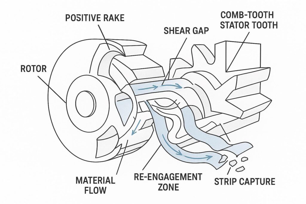
포지티브 레이크(Positive-rake) 오목형 커터
칼날 형상 설계를 통해 스트립이 그대로 통과하지 않고 절단 영역 내부로 다시 끌려 들어가도록 유도할 수 있습니다.
에이 포지티브 레이크, 오목형(concave) 커터 프로파일은 스트립이 발생하기 쉬운 원료 공급 조건에서 두 가지 유용한 역할을 합니다:
- 포착(Capture): 오목한 포켓과 레이크 각도(경사각) 덕분에 얇고 유연한 원료가 뭉개지지 않고 확실하게 잡힙니다.
- 재물림(Re-engage): 스트립이 빠져나가려고 할 때, “걸어서 되돌리는(hook-and-return)” 형상 설계가 부하 상태에서 고정 칼날(stator)과 다시 맞물릴 확률을 높여줍니다.
목표는 단순히 공격적인 절단력을 확보하는 것이 아니라, 과도한 미분(fines)을 생성하지 않으면서 길이를 단축시키는 안정적이고 반복 가능한 물림을 구현하는 것입니다.
빗형(Comb-tooth) 스테이터 베드
빗형 스테이터는 제어된 “스트립 방지 고정 장치”처럼 작동합니다. 단일 평면 앤빌(anvil) 모서리 대신, 빗 모양의 이빨이 국소적인 맞물림 지점을 여러 개 형성합니다.
Benefits for strip control:
- More bite points → more chances to catch long, flexible pieces.
- Shorter unsupported spans → less ability for strips to bow away.
- More consistent presentation → less sensitivity to small changes in feed density.
In strip-heavy RDF/SRF, a comb stator is often the difference between “mostly OK” and “stable P98.”
Edge prep and metallurgy
Edge sharpness matters—but in mixed waste it’s not just initial sharpness, it’s how the edge fails.
Two failure modes matter for strip control:
- Rounding (plastic deformation / wear): edges stop biting film and start pulling it.
- Micro-chipping: edges develop discontinuities that increase wrap initiation and heat.
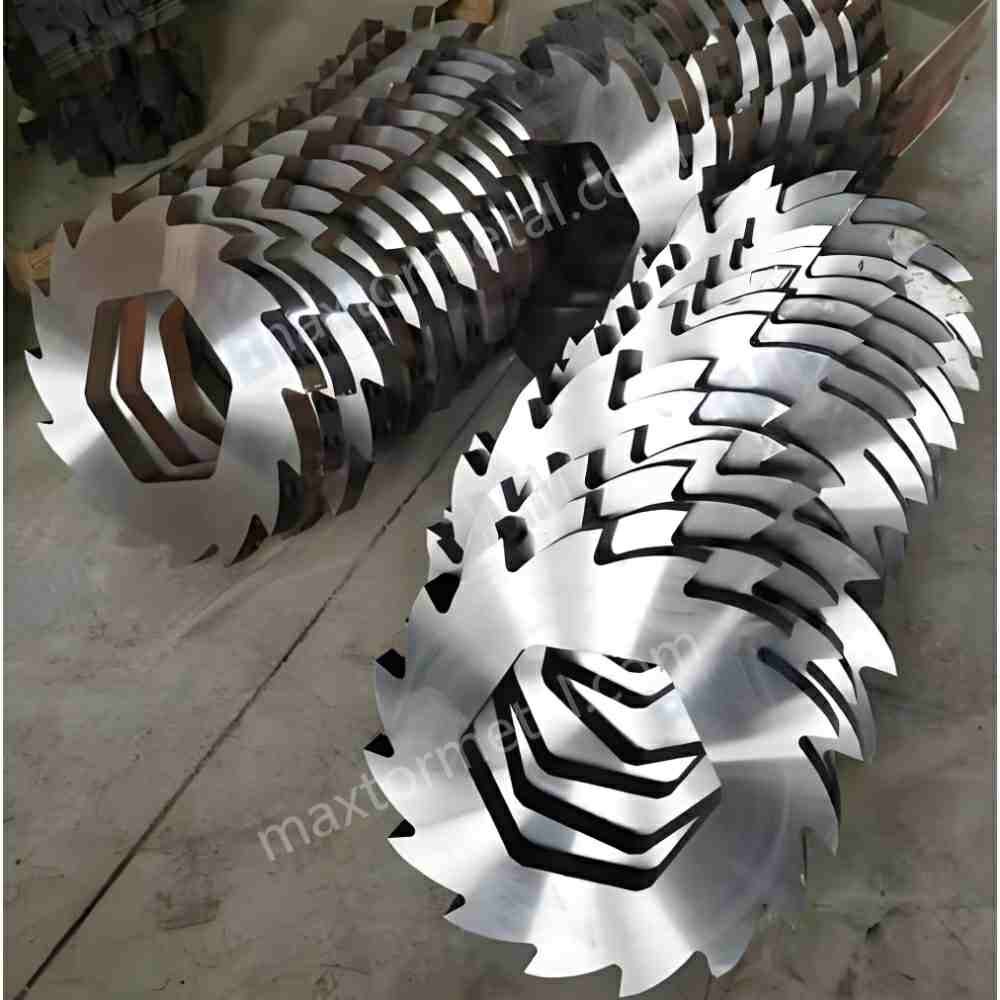
A practical QC approach—consistent with how Maxtor Metal positions its manufacturing discipline—is to treat shredder knives like a controlled wear component:
- verify incoming steel chemistry and traceability (heat/lot control),
- control heat treatment and hardness consistency batch-to-batch,
- confirm grind geometry and edge preparation against drawing tolerances,
- and validate fit-up so aftermarket knives don’t create clearance drift.
For the incoming-inspection workflow behind that verification—spec control, CMM sampling plans, and MTR documentation—see 애프터마켓 파쇄기(shredder) 나이프 조달: 사양 관리, CMM 계획, MTR 검증 및 기능적 적합성 검증..
That “OEM-fit” emphasis is not marketing fluff—it’s an engineering requirement. If the knife set cannot repeatably hold designed clearances and seating, you can’t hold particle size distribution.
For reference when specifying or qualifying replacement knives, the Maxtor Metal product page for Maxtor Metal shredder blades is a convenient place to align terminology and typical supply scope without turning the process discussion into a sales pitch.
요약하자면: positive-rake concave cutters and comb-tooth stators work together to capture and re-engage flexible material, but the gains only hold if edge metallurgy and knife fit are controlled to spec.
스크린 및 전단 간격(Gap)
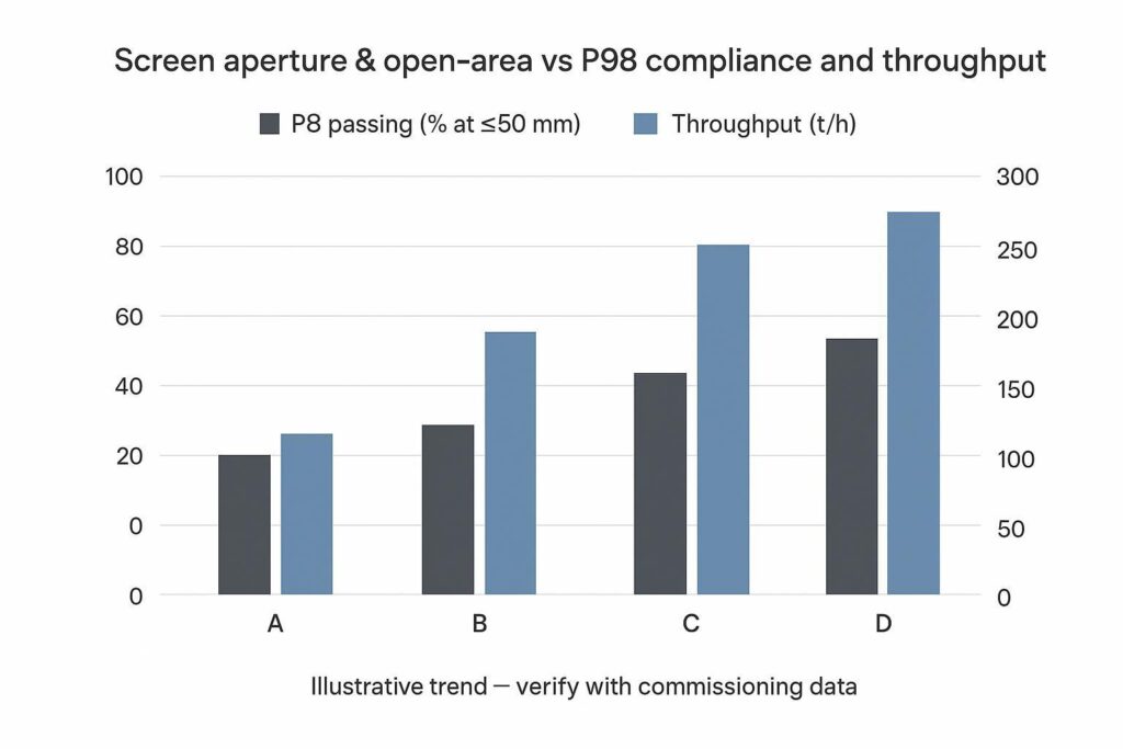
Aperture and open-area
For a spec like ≤50 mm at ≥98% passing, you’re optimizing the coarse tail—not the average size.
- Smaller apertures usually tighten the coarse end (better P98) but increase recirculation and energy.
- Higher OAR improves discharge capacity but can reduce “re-cut opportunities” if the system lets marginally-long pieces orient and slip through.
Screening references commonly define open area as the ratio of net aperture area to total screen area; higher open area increases available passage and capacity, while reduced open area can promote retention and blinding.
The right way to choose is to treat aperture and OAR as a pair and validate against both compliance and throughput.
A practical commissioning pattern:
- Start with the aperture that makes the spec achievable with margin.
- Then tune OAR (screen thickness, hole pattern, anti-blinding features, cleaning) to recover throughput without sacrificing P98.
If you need a standards-aligned way to define and report “oversize” and “long particles,” SRF particle-size determination methods like EN 15415-2 (maximum projected length method for large dimension particles) provide a defensible measurement framework you can cite in acceptance documentation.
Shear-gap tolerances
Gap control is the unglamorous lever that holds everything together.
Recommendations that usually survive real-world RDF/SRF variability:
- Set a target gap 그리고 maximum allowable spread across the rotor width.
- Track gap drift as a maintenance KPI alongside kWh/t.
- When changing knife sets, treat clearance verification as a sign-off step, not an operator “feel” task.
For typical secondary shredder classes (e.g., 1.5 m to 2.8 m rotor width processing mixed RDF/SRF), target shear gap tolerances should be held between 0.5 mm and 1.2 mm depending on the rotor-to-stator setup. Furthermore, when reporting particle size distribution against EN 15415-2 or EN ISO 21640 standards, sampling mass and increment controls must account for measurement uncertainty (typically ±1.5% to ±2.0% P98 variance) caused by moisture variations and local film concentration.
Even small clearance changes can move you from “short chips” to “long ribbons” on film-heavy loads. The tolerance chain that keeps this gap stable across a multi-shaft rotor—GD&T callouts, spacer selective fit, and post-assembly TIR verification—is covered in 편마모 해결: 다축 슈레더 나이프의 누적 공차(Tolerance Stacking) 가이드.
Anti-wrap and deflectors
Anti-wrap isn’t only about avoiding downtime; it’s about keeping the material in the intended cut path.
Effective measures include:
- rotor-end and shaft deflectors that prevent film migration into dead zones,
- scrapers that keep the screen and stator interface clean,
- and maintaining edge condition so film is sheared rather than pulled.
When wrap events are frequent, treat them as a process symptom: it often means the system is spending too long in recirculation because P98 is not being achieved efficiently.
요약하자면: choose aperture for the P98 target first, then tune open-area ratio and gap uniformity to recover throughput without giving up compliance.
투입 제어(Feed control) 및 리스크

Residence-time stability
Residence time is the bridge between particle size and energy.
If feed swings, you can temporarily “pass” P98 by starving the chamber—but you’ll pay for it in throughput instability. Conversely, if you overload, you’ll see more smearing and strip formation.
Aim for:
- stable ram pressure / feed conveyor load,
- stable amperage profile,
- and stable recirculation return rate (oversize loop).
Tramp metal and moisture
Tramp metal triggers both performance loss and risk:
- It damages edges (accelerating strip formation).
- It forces operators to open gaps to avoid catastrophic contact.
Moisture changes friction and material handling:
- wet film and textiles are more likely to mat and wrap,
- and wet fines can blind screens, effectively reducing open area.
Upstream protection (magnets/metal detection) and moisture-aware operating windows are often the cheapest “strip control” you can buy.
Thermal growth allowances
Thermal growth shows up as clearance drift.
Even if your cold setup is perfect, sustained high-load operation can change rotor/stator relationships. If the machine design has limited thermal compensation, you may need:
- defined warm-up checks,
- thermal-state-specific gap targets,
- and stricter sign-off after long runs on high-friction feeds.
요약하자면: residence-time swings, tramp metal, moisture, and thermal growth all show up as the same symptom—clearance and engagement drift—so feed stability protects the gap settings you already tuned.
KPI, 시운전(Commissioning) 및 ROI
Sieve plans and wording
If you want acceptance that doesn’t devolve into arguments, write your test plan like a contract.
Use clear definitions and methods:
- Reference ISO 21640 for SRF specification/class framing via the ISO catalog listing for ISO 21640:2021, Solid recovered fuels — Specifications and classes.
- Define particle size reporting using a sieve method standard like ISO 2591-1:1988 (Test sieving — General principles).
- For long/oversize particles, cite a method aligned to SRF practice such as the public catalog entry for “EN 15415-2:2012 (Maximum projected length method)”.
Then specify:
- sieve stack (aperture sizes),
- sample basis (as received vs dry),
- how many increments and total mass,
- P98 calculation method,
- and pass/fail wording (including what happens on a retest).
Throughput, kWh/t, uptime
For line economics, track three KPIs together:
- Throughput (t/h): the obvious one.
- Specific energy (kWh/t): the hidden cost of over-recirculation.
- Uptime (%): wrap events and screen blinding will dominate this.
A common failure is optimizing only one metric (e.g., smallest aperture to “make spec”) and losing overall efficiency. P98 is the constraint; throughput and kWh/t are the optimization variables.
Tuning matrix and payback
Commissioning should be treated like controlled experimentation.
Build a tuning matrix with rows like:
- cutter geometry (baseline vs positive-rake concave),
- stator type (flat vs comb),
- screen aperture,
- screen OAR/condition,
- shear gap setpoint,
- feed setpoint (ram pressure/conveyor speed),
- moisture band.
출력:
- P98 compliance,
- throughput,
- kWh/t,
- wrap events per shift,
- knife life (hours or tons between regrinds).
Payback usually comes from a combination of:
- fewer wrap stoppages,
- lower kWh/t at the same spec,
- and longer stable intervals between gap resets/knife interventions.
Field Case Study: 15 t/h Secondary Shredding Line Optimization
Case data below is drawn from an anonymized field commissioning engagement; customer identity and site details are withheld, and results reflect this specific line configuration rather than a guaranteed outcome.
To evaluate the combined impact of cutter geometry, comb stators, and shear gap management, a performance audit was conducted on a 15 t/h commercial RDF/SRF secondary shredding line handling high-film municipal solid waste fractions.
| Parameter / Metric | Baseline Setup (Flat Stator, Conventional Blades) | Optimized Setup (Positive-Rake, Comb Stator, 0.8mm Gap) | Performance Delta |
|---|---|---|---|
| P98 Passing (≤50 mm) | 89.0% (Non-compliant) | 98.5% (Compliant) | +9.5 percentage points |
| Specific Energy (kWh/t) | 21.5 kWh/t | 18.5 kWh/t | -14.0% energy reduction |
| Throughput Stability | 12.2 t/h average | 15.1 t/h average | +23.8% effective capacity |
| Rotor Wrap Events | 3.0 stops per 8-hr shift | 0.2 stops per 8-hr shift | 93.3% reduction in wrap downtime |
By stabilizing particle re-engagement and preventing film slippage, the line eliminated over-recirculation, allowing higher throughput at a significantly lower specific energy footprint.
The optimized configuration in this engagement used Maxtor Metal comb-tooth stator blades and positive-rake cutters specified to the OEM clearance drawing—consistent with the fit-and-traceability discipline described above.
When knife fit and repeatability are part of the constraint, linking your knife specification/qualification documentation to the relevant part families helps keep procurement and maintenance aligned without turning the engineering plan into a vendor selection exercise.
요약하자면: track P98, throughput, and kWh/t together, not one at a time—the case data above shows how a coordinated tuning matrix converts compliance gains into real energy and uptime savings.
FAQs:
Q: 파쇄기(Shredder)에서 짧은 입자가 아닌 길게 찢어진 불량품이 발생하는 이유는 무엇인가요?
A: 길게 찢어진 원단이 발생한다는 것은 연성 재질의 물량이 절단 영역에서 반복적으로 물려 파쇄되지 않고 늘어나거나 슬립(Slip)되어 통과하고 있음을 의미합니다. 가장 흔한 원인은 무뎌진 칼날(Dull edges), 과도하거나 불균일한 전단 간격(Shear gap), 그리고 경계 사이즈의 파쇄편이 방향을 틀어 통과할 수 있게 만드는 스크린/OAR 조건입니다.
Q: RDF/SRF 입도 제어에서 "P98 ≤50 mm"는 무엇을 의미하나요?
A: 시료 전체 질량의 98%가 50 mm 스크린 기준을 통과함을 의미합니다(질량 기준 오버사이즈 초과분은 2% 미만). 이는 길게 찢어진 불량품이 주로 나타나는 입도 분포의 거친 입자 영역(Coarse tail)에 집중하는 관리 지표입니다.
Q: 98% 이상의 통과율(P98)로 ≤50 mm 입도를 달성하기 위해 스크린 망목(Aperture) 크기를 어떻게 선정해야 하나요?
A: 최악의 투입 조건(필름 및 섬유류 비율이 높은 조건)에서도 안전 마진을 두고 P98 목표를 달성할 수 있는 스크린 망목 크기로 시작하십시오. 그런 다음, 망목 크기를 즉시 키우기보다는 개구율(Open area) 향상, 망목 막힘 방지(Anti-blinding) 기능 강화, 투입 안정성 개선을 통해 처리량(Throughput)을 회복하는 것이 정석입니다.
Q: 스크린의 "개구율(Open Area Ratio)"이란 무엇이며, 왜 처리량(Throughput)에 영향을 미치나요?
A: 개구율은 전체 스크린 표면적 중 실제 관통되어 있는 개구 타공 구멍의 비율을 의미합니다. 개구율이 높을수록 입자가 통과할 수 있는 유효 면적이 넓어져 파쇄 처리량이 향상됩니다. 반면, (디자인 문제나 망목 막힘/Blinding으로 인해) 유효 개구율이 낮아지면 처리량이 감소하고, 파쇄실 내 재료 체류 시간 및 재순환 부하(Recirculation load)가 증가합니다.
Q: 길게 찢어진 불량품을 줄이기 위해 전단 간격 공차(Shear gap tolerance)를 얼마나 정밀하게 유지해야 하나요?
A: 연성 재질의 물량이 미끄러지지 않고 지속적으로 물려서 절단될 수 있을 만큼 정밀해야 합니다. 실무적으로 가장 중요한 것은 로터 전체 폭(Rotor width)에 걸친 공차의 균일성과 마모 및 열팽창 상태에서도 설정값을 유지하는 것입니다. 이를 서명 승인(Sign-off) 절차가 포함된 관리 공차 항목으로 다루어야 합니다.
Q: 입도 규격을 강화했을 때 로터 감김 현상(Wrap events)이 오히려 악화되는 이유는 무엇인가요?
A: 규격을 강화하면 파쇄실 내 체류 시간(Residence time)과 재순환량이 증가합니다. 이때 나이프 형상, 전단 간격 제어(Shear gap control) 및 감김 방지 하드웨어가 물량을 깔끔하게 재물림하도록 최적화되어 있지 않다면, 늘어난 재순환량이 감김 리스크로 이어져 비가동 다운타임을 발생시킵니다.
Q: 애프터마켓(Aftermarket) 파쇄기 칼날도 P98과 같은 입도 규격을 유지할 수 있나요?
A: 가능합니다 — 단, 장비가 설계된 클리어런스를 유지할 수 있도록 요구되는 체결 정밀도와 나이프 형상을 준수하여 제조 및 검증된 칼날이어야 합니다. 실무적으로 이는 금속 재질 및 열처리 품질의 일관성, 도면 공차에 맞춘 정밀 연삭, 그리고 간격 벌어짐(Drift)을 방지하는 우수한 장착 재현성을 의미합니다.
Q: 길게 찢어진 불량품(Long strips)에 대한 분쟁을 방지하기 위해 인수 검사(Acceptance test) 조항을 어떻게 작성해야 하나요?
A: (1) 시료 채취(Sampling) 방법, (2) 체(Sieve) 구성 및 기준, (3) P98 산출 방식, (4) "대형 입자" 측정 방식(예: 최대 투영 길이)을 명확히 정의하십시오. 그런 다음 명확한 합격/불합격(Pass/fail) 판정 기준과 재시험(Retest) 조건을 명시적으로 작성해야 합니다.
결론

길게 찢어진 불량품(Long strips)은 원인을 알 수 없는 결함이 아닙니다. 연성 재질 물량이 절단 칼날에 다시 물리는 재물림(Re-engagement) 과정을 피할 때 발생하는 예견된 결과입니다.
길게 찢어진 불량품(Long-strip rejects)을 구조적으로 eliminate하고 P98 ≤50 mm 입도 규격 준수를 지속적으로 유지하기 위해, 공장 관리자 및 기술 팀은 다음 세 가지 핵심 영역에 집중해야 합니다.
- 시스템 대응책 (System Countermeasures):연성 필름류의 적극적인 재물림을 유도하기 위해 양(+)의 경사각을 가진 오목 형상 회전도(Positive-rake concave cutters)와 빗형 고정도(Comb stators)를 조합하여 적용하십시오. 파쇄 처리량을 유지할 수 있도록 최적화된 개구율(OAR)과 망목 막힘 방지(Anti-blinding) 프로토콜을 유지하면서 P98 요구 조건에 맞게 스크린 망목 크기를 설정하십시오. 전단 간격(Shear gaps)은 로터 전체 폭에 걸쳐 정밀하게(0.5–1.2 mm) 균일하게 유지하고, 안정적인 투입 제어를 통해 동력 피크 및 체류 시간(Residence time)의 편차를 제거해야 합니다.
- 신뢰할 수 있는 인수 검사 프로토콜:ISO 21640 및 EN 15415-2 표준에 부합하는 표준화된 체 가름 시료 채취 계획을 적용하십시오. 최고 필름 투입 부하 조건에서 비에너지 소비량(kWh/t) 및 처리량(t/h)과 함께 P98 준수 여부를 추적하여 품질 규격 강화가 공장의 수익성을 저해하지 않도록 관리해야 합니다.
- 램프업(Ramp-Up) 및 표준 작업 절차(SOP):커터 형상, 스크린 설정, 전단 간격을 검증하는 체계적인 시운전(Commissioning) 매트릭스를 실행하십시오. 장기적인 성능을 유지하기 위해 정기적인 간격 검증, 열팽창 점검, 나이프 교체 기준을 표준 작업 절차(SOP)에 정례화하여 반영해야 합니다.
요약하자면: 커터 형상, 스크린, 전단 간격 및 투입 제어를 아우르는 단기 미세 조정 매트릭스부터 시작하십시오. 간격 점검, 나이프 교체, 스크린 상태 관리 SOP를 확립한 후, 가동 중단 없는 정밀 모니터링 하에 출력을 높여 P98 규격 준수가 가동률(Uptime) 저하로 이어지지 않도록 하십시오.
Article Technical Review & Expertise Notice
Author & Technical Support: Jerry Chu
Role: Technical Support Specialist | After-sales Service & Application Engineering, Maxtor Metal
경험: 10+ years of field troubleshooting across industrial cutting, paper manufacturing, plastics size reduction, metal slitting, and timber processing applications. Specializes in solving edge-wear, burr formation, and fine dust issues in high-demand size-reduction machinery.
Professional Certifications: Project Management Professional (PMP)®, Certified Maintenance & Reliability Professional (CMRP)®.
Quality & Editorial Process: Content based on field commissioning logs, OEM tooling specs, and ISO/EN solid recovered fuel compliance frameworks. Verified by Maxtor Metal’s application engineering team.

 English
  Spanish
  Italian
  French
  Portuguese
  Russian
  German
  Arabic
  Hindi
Hindi  Vietnamese
  Indonesian
  Japanese
  Korean