

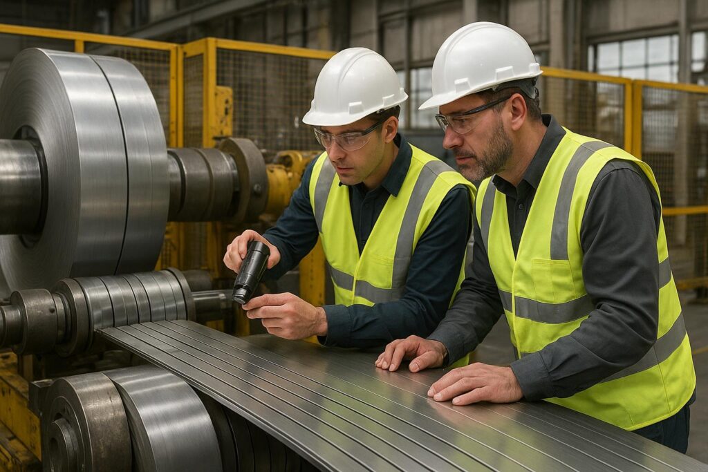
슬리팅 버(Burr) 저감은 방치할 경우 막대한 비용 손실로 직결되는 대표적인 디테일 문제입니다. 버 발생은 고객 클레임을 유발하고, 후공정 성형(Forming) 문제를 일으키며, 나이프의 수명을 은연중에 단축시킵니다.
이 핸드북은 탄소강, AHSS, 스테인리스 및 알루미늄을 가공하는 코일 슬리팅 라인에서 10년 이상의 현장 트러블슈팅 경험을 쌓은 Maxtor Metal의 기술 지원 전문가 Jerry Chu가 편찬했습니다. 이 핸드북은 Maxtor Metal의 애플리케이션 엔지니어링 팀의 상호 검토(peer-review)를 거쳤으며, 철저한 셋업 범위 준수, 신속한 근본 원인 규명, 일관된 측정을 핵심 성공 방식으로 삼는 실무적이고 검증 우선적인 정신으로 작성되었습니다.
귀사의 라인에서 롤러 시어링 칼날(또는 이와 동등한 슬리터 나이프 시스템)을 사용하는 경우에도 아래 원칙은 동일하게 적용됩니다. 절단을 제어된 파단/전단 현상으로 취급한 다음, 실제로 버(burr)를 발생시키는 몇 가지 변수를 통제하십시오. 롤러 전단 툴링에 특화된 재질 선택, 클리어런스 설계 및 고장 모드 진단에 대해서는 Maxtor Metal의 다음 가이드를 참조하십시오. 로터리 슬리터 나이프 및 롤러 시어 칼날 엔지니어링 가이드.
이 핸드북에서 다루는 내용
근본 원인(간격/오버랩, 나이프 상태, 정렬, 속도, 윤활, 장력)을 식별하고, 재질 그룹별 초기 세팅 범위를 정의하며, 검사, 합격 기준(공차 범위) 및 ROI 추적을 표준화하여 엣지 버(Edge burr)를 저감하기 위한 현장 및 엔지니어링 참조 가이드입니다. 이 가이드는 고객의 도면 요구 사항(Customer print)을 대체하지 않습니다. 최적의 세팅 값을 더 빠르게 찾기 위해 활용하고, 이후 자사의 공정 능력(Process capability)을 기준으로 검증하십시오.
대상 독자
강종 및 두께 변화에 따라 슬리팅 품질을 미세 조정하는 공정 엔지니어, 아버(Arbor) 상태, 런아웃(Runout) 및 나이프 조립체(Stack)의 정밀도를 책임지는 보전 팀장, 절단면 품질과 설비 가동률(Uptime)의 균형을 맞추는 생산 관리자, 그리고 공구, 스페이서(Spacer) 및 재연삭 경제성을 평가하는 기술 구매 담당자.
실제 가동 라인에서 활용하는 방법: 먼저 측정 표준화(측정 정밀도)를 확립하십시오 → 설정값을 변경하기 전에 근본 원인 매트릭스를 사용하여 가장 유력한 변수를 먼저 식별하십시오 → 재질별 세팅 범위를 시작점으로 적용한 후 미세한 단위로 조정하십시오 → 설정 변경 후에는 반드시 단경장 검증 시편(Verification strip)을 시ตัด하고 재측정하십시오.
추적해야 할 핵심 지표
스트립 두께 대비 버(Burr) 높이 비율(및 고객 지정 시 절대 높이) · 폭 공차 및 편차(스페이서/조립체 누적 오차 포함) · 가동률 / OEE 영향(세팅 시간, 교체 시간, 비planned 중단) · 공구 수명(재연삭당 처리 톤수, 세트당 처리 톤수 및 파손 모드: 마모 vs 미세 치핑).
핵심 요약: 도면 요구 사항(Print)을 기준으로 기록하고 검증하지 않은 버(Burr) 개선 효과는 지속될 수 없습니다.
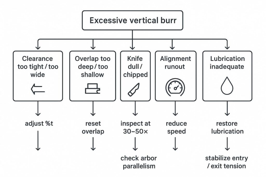
슬리팅 버(Burr) 저감을 위한 근본 원인 매트릭스
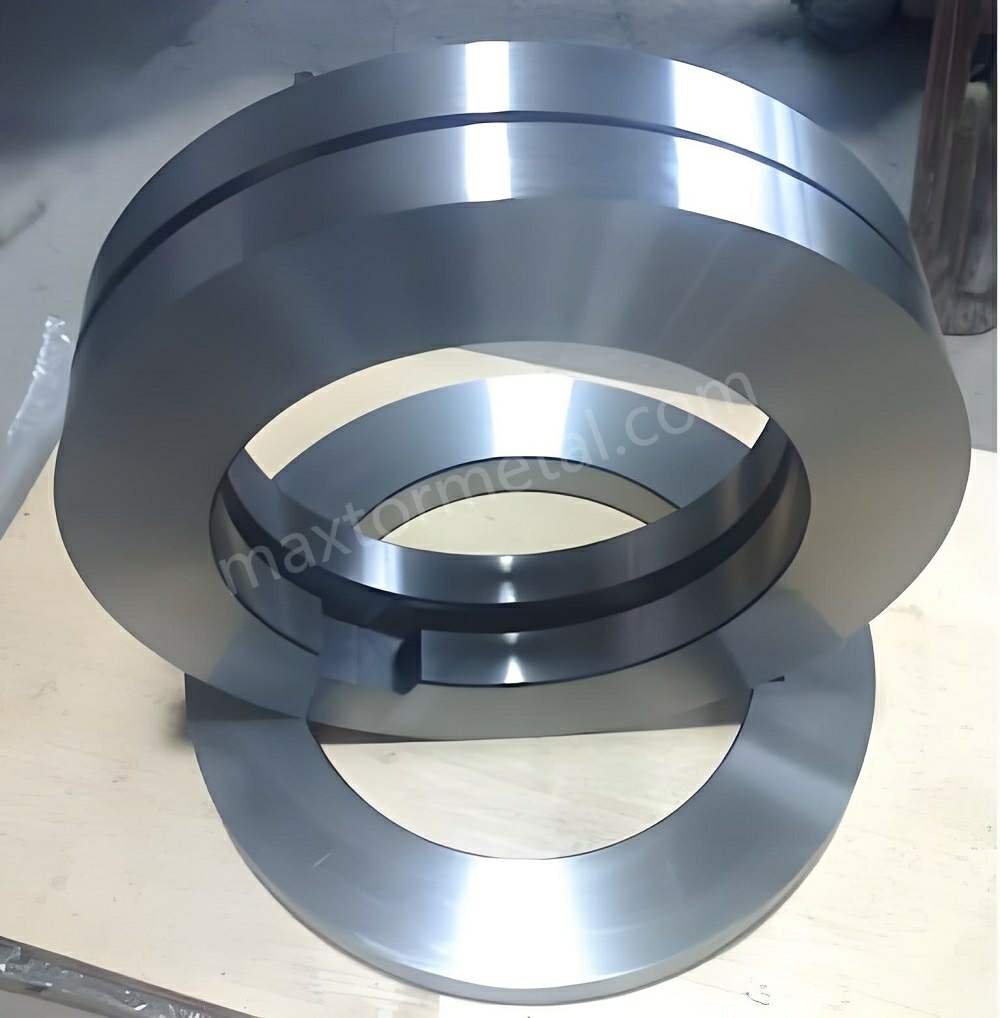
클리어런스 및 오버랩 오류
수평 클리어런스와 수직 오버랩은 종종 가장 영향력이 크고 빠르게 테스트할 수 있는 변수이므로 여기에서 시작하십시오. 실무적인 업계 지침에서는 버(burr) 발생의 원인을 일관되게 부적절한 클리어런스와 과도한 오버랩으로 지목하고 있습니다.The Fabricator: “코일 슬리팅 시 발생하는 슬릿 결함을 방지하는 방법” (2006)
점검 사항 (순서대로):
- 수평 클리어런스 (%t): 너무 좁으면 가장자리가 문질러지거나 말릴 수 있고, 너무 넓으면 전단되지 않고 찢어질 수 있습니다. (흔히 다음으로 논의됨: 슬리터 나이프 클리어런스 백분율.)
- 수직 오버랩: 너무 깊으면 버(burr)와 가장자리 손상이 증가하고, 너무 얕으면 절단이 불안정해질 수 있습니다. (귀사의 슬리터 오버랩 설정 은 %t만큼이나 중요합니다.)
- 버(burr) 편향성: 한쪽 가장자리에 버가 더 심하게 발생하는 것은 단순히 “잘못된 %t” 때문이 아니라 정렬/스택 문제인 경우가 많습니다.”
조치 방법:
- 클리어런스를 다음 범위로 재설정하십시오: 소재별 기준 시작 범위 (소재별 셋업 범위 참조).
- 깊이에 따라 버(burr)가 증가하는 경우 오버랩을 단계적으로 조금씩 줄이십시오.
- 스트랜드 간에 버(burr) 패턴이 일관되지 않은 경우 스택 대칭성과 스페이서 상태를 다시 확인하십시오.
For the full mechanics behind overlap-to-clearance coordination — including burnish/break ratio interpretation, material-specific penetration windows, and arbor positioning best practices — see the rotary knife overlap settings guide.
잘못된 조치를 취하고 있음을 나타내는 고장 모드:
- 버(burr)가 일시적으로 감소했다가 몇 분 내에 다시 발생함 → 나이프 날 상태 또는 이물질/열 문제.
- 저속에서는 버(burr) 상태가 양호하나 생산 속도에서는 불량이 발생함 → 장력 안정성, 윤활 또는 동적 정렬 문제.
나이프 날카로움, 형상 및 코팅
버(burr)는 셋업 문제로 위장된 나이프 상태 문제인 경우가 많습니다.
점검 사항:
- 날 끝 반경 증가 (마모) 및 미세 치핑(micro-chipping) (특히 AHSS/스테인리스 가공 시).
- 형상 일관성 세트 전체의 형상 일관성 (베벨 대칭성, 페이스 런아웃).
- 갤링(Galling) / 픽업(pickup) 스테인리스 또는 알루미늄 가공 시 발생하는 현상 (“갑작스러운 버 발생”의 흔한 원인).
조치 방법:
- 검사 시점을 앞당기십시오. 품질이 저하되기 전에 날 상태를 점검하십시오.
- “마모로 인한 버”와 “치핑으로 인한 버”를 구분하십시오. 마모는 점진적으로 진행되지만, 치핑은 급격한 변화를 유발합니다.
- 고장 모드(갤링 대 연마 마모)에 부합하는 코팅 방식을 적용하십시오.
정렬, 속도, 윤활 및 장력
클리어런스/오버랩이 정상 범위 내에 있고 나이프 상태도 양호하다면, 다음 단계는 “라인 가동 중 절단 위치가 흔들리는 현상”을 의심해야 합니다.”
점검 사항:
- 조정: 아버 평행도, 나이프 페이스 런아웃, 가이드 및 세퍼레이터 센터링.
- 속도: 속도에 따라 버(burr)가 비선형적으로 증가하는 경우 열, 진동 및 스트립 제어 상태를 점검하십시오.
- 매끄럽게 하기: 윤활유 도포를 주요 날 제어 변수로 취급하십시오. 알루미늄 및 스테인리스 슬리팅의 경우, 펠트 패드나 미스트 노즐을 통해 도포되는 경량 합성유 또는 휘발성 윤활유는 마찰을 줄이고 나이프 표면에 소재가 달라붙는 현상(갤링)을 방지합니다. 후판 탄소강의 경우, 경계 윤활제가 전단 영역의 마찰열을 방출하여 나이프 날의 열적 연화를 방지합니다.
- 긴장: unstable entry/exit tension can distort strip, drive flutter, and produce edge damage.
Reference point: an industry association bulletin notes burr height can be minimized by attention to slitter rigidity, horizontal/vertical clearance, and resharpening discipline (Australian Steel Institute, Technical Bulletin TB-F2).
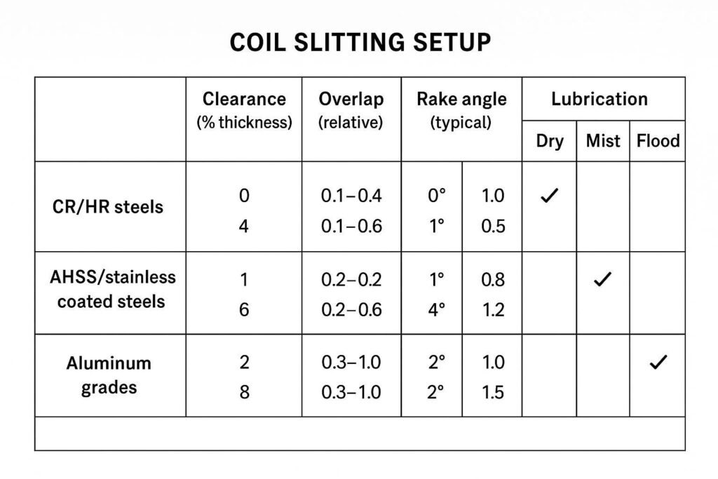
재질별 세팅 조건 범위
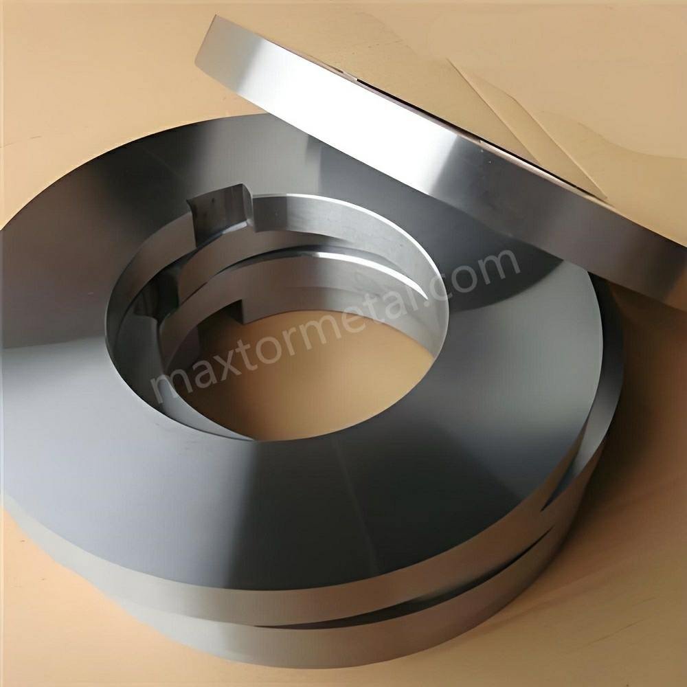
These are 시작 운전 범위 to shorten setup time and reduce trial-and-error. Always validate against your customer print and your line’s stiffness, knife diameter, and arbor condition. If you need the keyword-friendly phrasing: this section is your practical slitting setup window by material.
| Material Group | Horizontal Clearance (%t) | Vertical Overlap (mm / in) | Key Focus Areas |
|---|---|---|---|
| CR / HR Carbon Steel | 8% – 12% t (Mid-grade: ~10% t) | +0.25 mm to +0.50 mm (+0.010″ to +0.020″) | Balance shear-to-break ratio; avoid excessive overlap |
| AHSS / Stainless Steel | 10% – 15% t (High tensile: ~12% t) | +0.10 mm to +0.30 mm (+0.004″ to +0.012″) | Prevent micro-chipping; monitor edge radius & galling |
| Aluminum & Soft Alloys | 5% – 8% t (Tight alignment required) | +0.05 mm to +0.20 mm (+0.002″ to +0.008″) | Anti-galling coatings (DLC); prevent pickup & galling |
CR/HR steels
Starting intent: stable shear zone with minimal tearing.
Standard carbon steels feature balanced ductility and tensile strength, allowing a traditional 1/3 shear and 2/3 break edge ratio. Operating within 8%–12% t clearance achieves a clean fracture transition without excessive edge rolling or deep tearing.
- Clearance: start mid-window (~10% t), then tune toward minimum burr.
- Overlap: moderate; avoid “deep overlap as insurance.”
- Speed: increase only after burr is stable at low-to-mid speed.
- Lubrication: use consistent lubrication strategy to prevent heat-driven edge degradation.
Practical note: ASI’s TB-F2 bulletin illustrates that recommended clearances vary by need (general production vs minimum burr) and highlights that optimum clearance reduces burr.Australian Steel Institute Technical Bulletin TB-F2 (Shearing and slitting steel sheet and strip)
프로 팁: When you widen the window for throughput, document what you changed (clearance, overlap, speed, tension). Otherwise your next “same material” run won’t actually be the same.
AHSS, stainless, and coated steels
Starting intent: prevent chipping and edge cracking while maintaining burr control.
High-tensile AHSS and work-hardening stainless steels exhibit extreme yield strengths and low elongation. Wider clearance (10%–15% t) is critical to relieve peak side-thrust forces on the knife edge, preventing micro-chipping while accommodating the abrupt shear fracture characteristic of high-strength alloys.
- Clearance: keep within a controlled window (~12% t); avoid extremes.
- Overlap: conservative; too deep can spike edge damage.
- Knife condition: inspect more frequently; micro-chips matter.
- Lubrication: treat as critical—pickup and heat are common triggers.
- Tension: prioritize stability over maximum throughput.
Aluminum grades
Starting intent: prevent pickup/galling and protect edge finish.
Aluminum and soft non-ferrous alloys possess high ductility and a strong tendency toward material adhesion (galling). A tighter clearance (5%–8% t) prevents the soft strip from dragging and folding over the knife edge, which would otherwise form heavy, continuous roll-over burrs.
- Clearance: typically tighter than steels (5%–8% t), but only when alignment is proven.
- Overlap: conservative; avoid unnecessary depth.
- Lubrication: ensure the method matches the alloy and surface requirements.
- Knife surface condition: watch for pickup—small deposits can produce large burr changes.
공구(나이프) 선정 및 유지보수
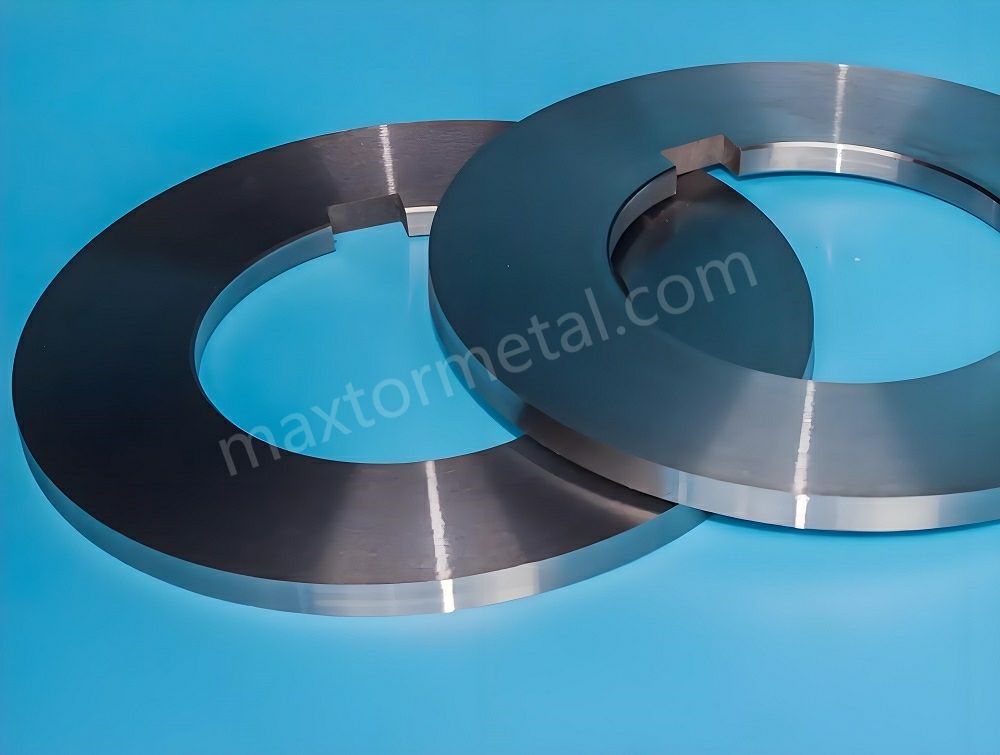
Knife steels and surface coatings
Maxtor Metal’s standard coating selection follows a failure-mode-first logic: 다운로드 가능 콘텐츠 is the default choice when galling and pickup are the primary risk (stainless steel, aluminum, and coated substrates); 티알인 is selected when abrasive wear and heat at the cutting edge dominate (high-speed AHSS processing, heavy-gauge carbon steel). For mixed-material lines, Maxtor Metal’s after-sales team typically recommends trialing one coating per failure mode on separate knife sets, then comparing tons-per-grind and edge condition trends over 3–5 production runs before standardizing.
Regrind intervals and edge inspection (30–50×)
A workable standard is to inspect at 30–50× magnification on a schedule that matches your burr tolerance and material severity.
To move from reactive grinding (sharpening only after burr complaints) to scheduled preventive maintenance, baseline your regrind frequency using practical tonnage thresholds:
| Material Severity | Typical Tonnage Interval (per Set) | Inspection Focus at 30–50× |
|---|---|---|
| Standard Carbon Steel (CR/HR) | Every 200 – 400 tons | Uniform edge radius growth (<0.03 mm) |
| AHSS / High-Strength Alloys | Every 100 – 180 tons | Micro-chipping, notch wear, edge breakdown |
| Stainless Steel / Aluminum | Every 120 – 250 tons | Metal pickup/galling, land face buildup |
What to standardize:
- Inspection triggers: first coil after changeover, after speed ramp, and when burr trends upward.
- Edge criteria: edge radius growth, micro-chips, pickup, and uneven wear.
- Regrind rule: regrind before burr becomes your “alarm,” not after.
What failure looks like:
- You only regrind after burr fails the customer spec → your process is reactive, not controlled.
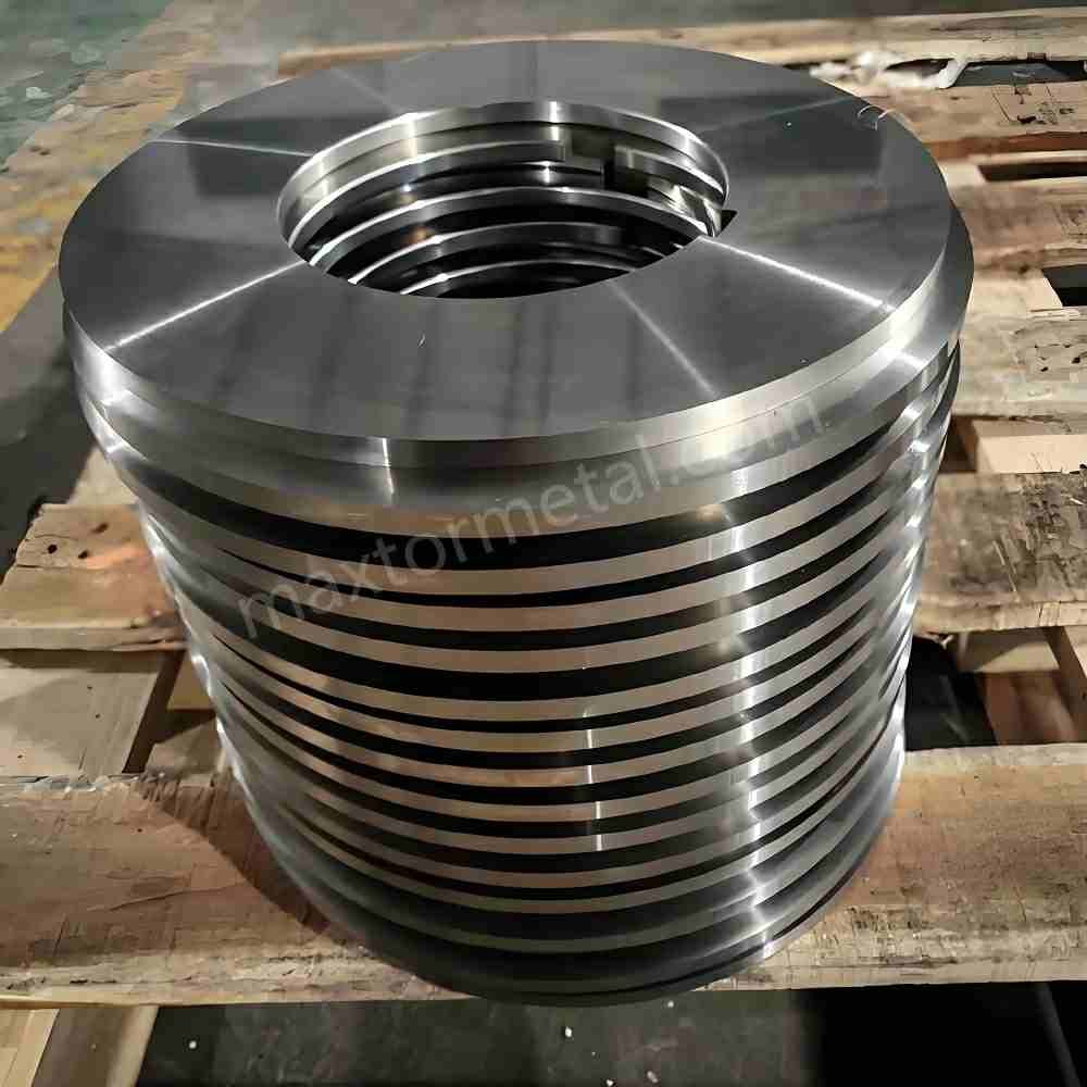
Spacer accuracy and stack integrity
Spacer and stack control is a width-tolerance problem 그리고 a burr problem.
What to standardize:
- Spacer verification and traceability (measured thickness, wear history).
- Stack build procedure (cleanliness, torque discipline, consistent orientation).
- Periodic checks for cumulative error across multi-knife setups.
What failure looks like:
- Width drift over a run, plus burr variability strand-to-strand → stack integrity and runout are suspects.
For spacer tolerance specifications, rubber ring compression targets, and a rebuild checklist template, see the precision slitting spacers and rubber rings guide.
정렬(Alignment) 및 장력 제어

Arbor parallelism and runout checks
If your arbors are not parallel or runout is uncontrolled, clearance becomes “different at every angle.”
Practical checks:
- Measure runout on relevant surfaces (arbor, knife face seating).
- Confirm parallelism across the working width.
- Re-check after maintenance events and after any tooling crash.
For a structured runout verification procedure — covering dial indicator setup, TIR acceptance tiers, and blue-check protocol — see the OEM 슬리터 나이프 설계도: 스핀들 끼워맞춤 감사, ISO 공차 및 TIR 게이트.
Passline, guides, and separator setup
Poor strip guidance can add lateral forces that change the effective cut.
Setup focus:
- Guides centered and consistent across the line.
- Separators aligned to prevent edge contact that creates secondary burr.
- Confirm the strip is not being “steered” into the knives.
Entry/exit tension and recoiler settings
Tension instability can look like a knife problem.
Controls to standardize:
- Entry/exit tension setpoints by grade and thickness.
- Procedures for speed changes (ramp rates) that don’t induce strip flutter.
- Clear rules for when to prioritize burr control over throughput.
측정, 인수 검사 및 ROI 추적
Burr measurement and logging
To reduce burr reliably, define measurement like a process parameter:
- Where to measure (edge location and distance from coil start/end)
- Sampling frequency (per coil, per slit, per changeover)
- Method (microscope, optical measurement, or profilometry) and operator training
Log at minimum:
- material grade, thickness, coating
- clearance (%t) and overlap setting
- knife set ID, regrind count, inspection findings
- line speed, lubrication mode, tension setpoints
- burr height results (and scrap/rework events)
Acceptance bands and documentation
Align your acceptance bands to the customer print—not tribal knowledge.
For drawing/spec language, ISO 13715 is the primary international reference for indicating and dimensioning edges of undefined shape (including burr/undercut indications) on technical documentation. Industry practice guidance from major manufacturing and steel industry associations consistently emphasizes establishing clear edge condition tolerances prior to production runs.
Practical approach:
- Convert the customer requirement into a measurable acceptance band (absolute or %t).
- Include side designation when relevant (which side burr is acceptable on).
- Keep records auditable: who measured, what method, what calibration state.
If your team uses a rebuild checklist and burr trend log as part of this process, Maxtor Metal’s slitting spacers and ring rebuild template set provides a ready-to-use format.
ROI/TCO templates and baselining
Burr reduction pays back when it reduces total cost per ton, not only when the edge “looks better.” Baseline before you change anything:
- Scrap and rework cost attributable to edge quality
- Downtime minutes from changeovers and unplanned stops
- Knife cost per ton (including regrinds and expedited orders)
- Customer returns/chargebacks tied to burr or edge condition
Then track deltas after you apply setup windows:
- Burr compliance rate (first-pass yield)
- Tons per grind and tons per knife set
- Setup time per changeover
If you’re building a knife material ROI case alongside setup window improvements, the rotary slitter knife ROI guide provides a cost-per-ton model covering PM-HSS vs tool steel trade-offs for AHSS, stainless, and aluminum.
Case Study: Automotive Stamping Supply Line Burr Reduction
A Tier-1 automotive coil slitting facility processing 1.5mm AHSS (DP780) experienced recurring edge burr exceeding 12% of material thickness, resulting in high customer reject rates and frequent knife micro-chipping.
By implementing the setup window and inspection protocol developed with Maxtor Metal’s technical support team — covering clearance/overlap reset, magnification-based inspection scheduling, and first-article verification discipline:
- Parameter Adjustment: Re-set horizontal clearance from an uncontrolled 18% t to a disciplined 11% t, and reduced vertical overlap from +0.60 mm to +0.20 mm.
- Knife Care: Shifted from post-failure grinding to 40× magnification optical inspection after every 150 tons.
- 결과: Average burr height dropped from 0.18 mm (12% t) 에게 <0.05 mm (3.3% t), meeting ISO 13715 specs. Tons per regrind increased by 42%, and annual edge-defect scrap cost was reduced by an estimated $30,000–$45,000 (based on material cost and reject rate data provided by the facility; anonymized and range-normalized).
- 제한 사항: These results were observed under stable incoming coil flatness and arbor runout below 0.010 mm. Lines with worn bearings, uncontrolled tension, or mixed operator discipline may see smaller gains from setup window changes alone.
FAQs:
Q: 코일 슬리팅 라인에서 버(Burr)를 가장 빠르게 저감하는 방법은 무엇인가요?
A: 수평 간격(Clearance)과 수직 오버랩(Overlap) 조정부터 시작한 다음, 30–50배율로 나이프 날의 상태를 검증하십시오. 속도에 따라 버의 크기가 변하는 경우, 장력의 안정성과 윤활 상태를 점검해야 합니다.
Q: 슬리터 나이프 간격(Clearance) 비율(%)은 얼마부터 시작해야 하나요?
A: 단일 고정 %가 아닌 재질 기반의 시작 범위를 적용하십시오. 범위의 중간값에서 시작하여 단경장 검증 시편을 시ตัด한 후, 버(Burr) 높이를 기록하며 미세한 단위로 조정해야 합니다.
Q: 수직 오버랩(Vertical overlap)을 늘리면 항상 버(Burr)가 줄어드나요?
A: 아닙니다. 과도한 오버랩은 오히려 버를 증가시키고 날 끝을 손상시킬 수 있습니다. 오버랩을 제어 변수로 관리하고, 절단 깊이가 깊어짐에 따라 버가 커진다면 오버랩을 줄여야 합니다.
Q: 버(Burr) 높이를 일관되게 측정하려면 어떻게 해야 하나요?
A: 정해진 측정 방식(현미경/광학 측정기/프로파일로미터), 고정된 채취 위치, 재현 가능한 기록 템플릿을 사용하십시오. 도면에서 허용하는 경우 버 높이를 두께 대비 비율(%)로 작성하십시오.
Q: 한쪽 절단면의 버(Burr)가 다른 쪽보다 더 심한 이유는 무엇인가요?
A: 이러한 현상은 정렬 상태, 런아웃(Runout), 또는 나이프 조립체/스페이서 문제로 인해 Clearance(간격)가 불균일해졌음을 의미합니다. 아버(Arbor)의 평행도, 나이프 안착 상태, 스페이서의 정밀도를 재점검하십시오.
Q: 슬리터 나이프(Slitter knives)는 얼마나 자주 점검하고 재연삭(Regrind)해야 하나요?
A: 버(Burr) 공차 및 재질의 강도/가공 부하에 맞춘 일정에 따라 30–50배율 확대경을 사용하여 점검하십시오. 버가 경고 수준(限界値)에 도달하기 전에 선제적으로 재연삭을 진행해야 합니다.
Q: 스테인리스 또는 알루미늄 슬리팅 시 소사/착부(Galling) 현상을 방지하는 최적의 코팅은 무엇인가요?
A: 소사 및 용착(Pickup) 위험을 줄이기 위해 일반적으로 DLC 코팅이 선택됩니다. 사용 중인 윤활 및 작업 속도 조건에서 금속 부착 상태, 버(Burr) 경향, 재연삭당 절단 톤수(Tons-per-grind)를 모니터링하여 검증하십시오.
Q: 운영(생산) 및 구매 부서에 버(Burr) 저감에 따른 ROI(투자 대비 효과)를 어떻게 입증해야 하나요?
A: 스크랩/재작업 비율, 설비 정지 시간(Downtime), 톤당 나이프 비용의 기준선(Baseline)을 먼저 수립한 후, 고정된 설정 범위와 일관된 측정 기준을 적용한 대조 시험 결과와 비교하십시오.
결론
- Summarize diagnostic priorities and parameter windowsDiagnostic priority is simple: (1) clearance/overlap, (2) knife condition, then (3) alignment/tension/lubrication. Use the setup windows as starting ranges, tune with small changes, and avoid simultaneous multi-variable “guessing.”
- Reinforce measurement discipline and verification against customer printsBurr control only holds if you measure it the same way every time and verify acceptance against the customer print language—especially when edges are specified using formal indication practices such as ISO 13715 (as described in the Acceptance bands section above).ISO 13715:2017 — ISO catalog page
- Next steps: pilot runs, data logging, and continuous improvementRun a short pilot on one representative grade, lock the logging fields, and convert your best settings into a controlled setup window.This is also where Maxtor Metal‘s after-sales support fits most naturally: if you want a second opinion on your regrind interval, coating selection, or clearance window for a specific material, Maxtor Metal’s technical support team can review your current setup parameters and edge inspection findings — and provide documented recommendations tied to your material grade, line speed, and knife geometry.Keeping tooling decisions, regrind intervals, and acceptance bands tied to the same dataset is how improvements survive operator changes and material mix shifts.
Author & Technical Reviewer
Jerry Chu
Technical Support Specialist, After-sales Service | Maxtor Metal
Jerry Chu is Technical Support Specialist at Maxtor Metal, with over 10 years of coil slitting troubleshooting experience across carbon steel, AHSS, stainless, and aluminum processing lines. His field work focuses on root-cause isolation for burr and edge quality failures — translating setup window discipline, knife inspection protocols, and regrind scheduling into measurable reductions in scrap, rework, and unplanned downtime. The diagnostic framework and setup windows in this handbook reflect the approach Jerry applies in Maxtor Metal’s after-sales technical support engagements. Certifications: PMP (Project Management Professional), CMRP (Certified Maintenance & Reliability Professional).

 English
  Spanish
  Italian
  French
  Portuguese
  Russian
  German
  Arabic
  Hindi
Hindi  Vietnamese
  Indonesian
  Japanese
  Korean